Falmec FDPLR15W5SS Guida utente
- Categoria
- Cappe da cucina
- Tipo
- Guida utente

Polar
FDPLR15W5SS (wall)
FDPLR15I5SS (island)
EN INSTRUCTIONS BOOKLET
IT LIBRETTO ISTRUZIONI
FR MODE D'EMPLOI
ES MANUAL DE INSTRUCCIONES

2
6”
1 5/8”
(40,9 mm)
1 5/8”
(40,9 mm)
6”
(152,6 mm)
6”
(152,6 mm)
1 5/8”
4 3/8”
(40,9 mm)
1 5/8”
(40,9 mm)
(111,7 mm)
4 3/8”
(111,7 mm)
4 3/8”
(111,7 mm)
4 3/8”
(111,7 mm)
6”
(152,6 mm)(152,6 mm)
8xØ2/8”
(Ø8x6 mm)
8 5/8”
(Ø220 mm)
15°
60°
Ø316 mm
12 7/16”
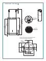
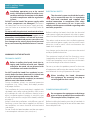
Posizione pulsantiera elettronica
Diameter of xing holes
Position for electronic pushbutton panel
2 6/8”
(70 mm)
1 1/8”
(30 mm)
3/8”
(10 mm)
26 6/8”
(680 mm)
30”
(760 mm)
Min 32 2/8”
(Min 820 mm)
(Ø350 mm)
Ø 13 6/8”
(Ø350 mm)
Ø 13 6/8”
(Max 1240 mm)
Max 48 7/8”
POLAR ISLAND
53 lb - 24 Kg

3
13 6/8”
(Ø350 mm)
36 5/8”
(930 mm)
2 6/8”
(70 mm)
17 “
(430 mm)
23 2/8”
(590 mm)
16 1/2” 15 1/8”
(420 mm) (385 mm)
8 3/8”
(211 mm)
6 1/2”
(164 mm)
15 3/8”
(389 mm)
32 7/8”
(835 mm)
6”
(154 mm)
4 7/16”
(113 mm)
8 1/2”
(218 mm)
6 5/8”
(Ø170 mm)
POLAR WALL
51 lb - 23 Kg
35 7/16”
12 6/8”
3/8”
(R10 mm)
13/32”
(R10 mm)
(324 mm)
Tempered
23 5/8”
(600 mm)
(900 mm)
12 2/8”
(310 mm)
35 7/16”
12 6/8”
3/8”
(R10 mm)
13/32”
(R10 mm)
(324 mm)
Tempered
19 11/16”
(500 mm)
(900 mm)
12 2/8”
(310 mm)
24 lb
11 Kg
22 lb
10 Kg
POLAR ISLAND GLASS POLAR WALL GLASS

4
max 28 2/8”
(max 720 mm)
(218 mm)
8 1/2”
min. 19 11/16”
(min. 500 mm)
(150 mm)
5 15/16”
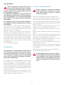
POLAR WALL

5
A
A = 24" - 35"
610 mm - 890 mm
(RECOMMENDED FOR
OPTIMAL PERFORMANCE)
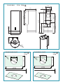
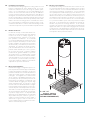
EN - Installation measurements
Recommended mounting height from cooking surface to hood
bottom is indicated by "A" in the drawing below. It is recom-
mended to install the hood in this range to optimize perfor-
mance. It is recommended to not exceed 35” (890mm) for di-
mension “A” as hoods mounted above this may be dicult to
reach for average height users and performance and eciency
will degrade. Hoods mounted below the lower measurement in
the “A” recommendation could result in damage due to heat and
present a re hazard and would avoid any warranty claims attrib-
utable to the lower mounting position. If available, also refer to
the cooking appliance manufacturer’s height clearance recom-
mendations and adhere to national and local building and re
codes which supersede any recommendations stipulated herein.
FR - Mesures pour installation
La hauteur de montage recommandée entre la surface de cuis-
son et la partie inférieure de la hotte est indiquée par le « A » dans
le dessin ci-dessous. Il est recommandé d’installer la hotte dans
cette plage pour optimiser sa performance. Il est recommandé
de ne pas dépasser les 890 mm (35 po) pour la dimension « A »,
car les hottes montées à une distance au-dessus peuvent être
diciles à atteindre pour les utilisateurs de hauteur moyenne, et
cela diminuera leur performance et ecacité. Les hottes mon-
tées en-dessous de la mesure inférieure de la recommandation
« A » pourraient s’abîmer par la chaleur et présenter un risque
d’incendie, ce qui annulerait toute réclamation de garantie at-
tribuable à la position de montage inférieure. Le cas échéant,
reportez-vous également aux recommandations du fabricant de
l’appareil de cuisson en ce qui a trait au dégagement en hauteur
et respectez les codes du bâtiment et de prévention des incen-
dies nationaux et locaux qui remplacent toutes les recommanda-
tions stipulées dans le présent document.
ES - Medidas instalación
La altura de montaje recomendada desde la su-
percie de cocción hasta el fondo de la campana
se indica con una "A" en el dibujo siguiente. Se
recomienda instalar la campana en este rango
para optimizar el rendimiento. Se recomienda
no exceder 35" (890mm) para la dimensión "A" ya
que las campanas montadas por encima de ésta
pueden ser difíciles de alcanzar para los usuarios
de altura media y el rendimiento y la eciencia se
degradarán. Las campanas montadas por deba-
jo de la medida inferior de la recomendación "A"
podrían resultar dañadas por el calor y presen-
tar un riesgo de incendio, y evitarían cualquier
reclamación de garantía atribuible a la posición
de montaje inferior. Si está disponible, consulte
también las recomendaciones de altura del fabri-
cante del equipo de cocina y respete los códigos
de construcción y contra incendios, nacionales y
locales, que sustituyen cualquier recomendación
estipulada en el presente documento.
IT - Misure per l'installazione
L’altezza di montaggio consigliata tra il piano cot-
tura e la parte inferiore della cappa è indicata dal-
la lettera “A” nella gura sottostante. Per ottenere
prestazioni ottimali, si raccomanda di installare la
cappa entro i limiti, massimo e minimo, mostrati
nella gura. È consigliabile che le dimensioni di
“A” non superino i 35” (890mm) in quanto le cap-
pe montate più in alto potrebbero presentare un
livello ridotto di rendimento ed ecienza, oltre
a risultare dicili da raggiungere da parte degli
utenti di altezza media. Al contrario, le cappe
montate al di sotto dell’altezza minima consiglia-
ta in “A” potrebbero danneggiarsi per il calore pro-
veniente dal piano cottura e presentare un rischio
di incendio. Si ricorda che la garanzia non rispon-
de di eventuali danni derivanti da un montaggio
in posizione troppo bassa. Se disponibile, fare
riferimento anche all’altezza libera raccomandata
dal produttore del piano cottura. In ogni caso, è
sempre necessario rispettare le norme edilizie e
antincendio in vigore, a livello sia nazionale sia
locale, le quali prevalgono su qualsiasi raccoman-
dazione contenuta nel presente.

6
T
V1
A
2
1
3
1
2
(446 mm)
18 3/8”
(113 mm)
4 7/16”
(113 mm)
4 7/16”
Ø8
V2
1
2
A
3
1 2
3 4
ø 5/16
8 mm
ø 1/4
6 mm
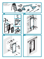
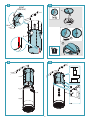
EN- tool required
FR- outil requis
ES- herramienta requerida
IT - Attrezzi necessari

7
(150 mm)
5 15/16”
V1
V1
1
1
2
3
M
4
6
8
7
9
5
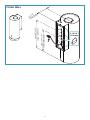
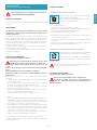
EN - Check valve installation (5);
Hood fastening (6-7-8-9);
FR - Installation du clapet anti-retour (5);
Fixation de la hotte (6-7-8-9);
ES - Instalación de la válvula antirretorno (5);
Fijación de la campana (6-7-8-9);
IT - Installazione valvola di non ritorno (5);
Fissaggio cappa (6-7-8-9);

8
(150 mm)
5 15/16”
POLAR ISLAND
x2
2
1
3
A B
C

9
A
A = 24" - 35"
610 mm - 890 mm
(RECOMMENDED FOR
OPTIMAL PERFORMANCE)
EN - Installation measurements
Recommended mounting height from cooking surface to hood
bottom is indicated by "A" in the drawing below. It is recom-
mended to install the hood in this range to optimize perfor-
mance. It is recommended to not exceed 35” (890mm) for di-
mension “A” as hoods mounted above this may be dicult to
reach for average height users and performance and eciency
will degrade. Hoods mounted below the lower measurement in
the “A” recommendation could result in damage due to heat and
present a re hazard and would avoid any warranty claims attrib-
utable to the lower mounting position. If available, also refer to
the cooking appliance manufacturer’s height clearance recom-
mendations and adhere to national and local building and re
codes which supersede any recommendations stipulated herein.
FR - Mesures pour installation
La hauteur de montage recommandée entre la surface de cuis-
son et la partie inférieure de la hotte est indiquée par le « A » dans
le dessin ci-dessous. Il est recommandé d’installer la hotte dans
cette plage pour optimiser sa performance. Il est recommandé
de ne pas dépasser les 890 mm (35 po) pour la dimension « A »,
car les hottes montées à une distance au-dessus peuvent être
diciles à atteindre pour les utilisateurs de hauteur moyenne, et
cela diminuera leur performance et ecacité. Les hottes mon-
tées en-dessous de la mesure inférieure de la recommandation
« A » pourraient s’abîmer par la chaleur et présenter un risque
d’incendie, ce qui annulerait toute réclamation de garantie at-
tribuable à la position de montage inférieure. Le cas échéant,
reportez-vous également aux recommandations du fabricant de
l’appareil de cuisson en ce qui a trait au dégagement en hauteur
et respectez les codes du bâtiment et de prévention des incen-
dies nationaux et locaux qui remplacent toutes les recommanda-
tions stipulées dans le présent document.
ES - Medidas instalación
La altura de montaje recomendada desde la su-
percie de cocción hasta el fondo de la campana
se indica con una "A" en el dibujo siguiente. Se
recomienda instalar la campana en este rango
para optimizar el rendimiento. Se recomienda
no exceder 35" (890mm) para la dimensión "A" ya
que las campanas montadas por encima de ésta
pueden ser difíciles de alcanzar para los usuarios
de altura media y el rendimiento y la eciencia se
degradarán. Las campanas montadas por deba-
jo de la medida inferior de la recomendación "A"
podrían resultar dañadas por el calor y presen-
tar un riesgo de incendio, y evitarían cualquier
reclamación de garantía atribuible a la posición
de montaje inferior. Si está disponible, consulte
también las recomendaciones de altura del fabri-
cante del equipo de cocina y respete los códigos
de construcción y contra incendios, nacionales y
locales, que sustituyen cualquier recomendación
estipulada en el presente documento.
IT - Misure per l'installazione
L’altezza di montaggio consigliata tra il piano cot-
tura e la parte inferiore della cappa è indicata dal-
la lettera “A” nella gura sottostante. Per ottenere
prestazioni ottimali, si raccomanda di installare la
cappa entro i limiti, massimo e minimo, mostrati
nella gura. È consigliabile che le dimensioni di
“A” non superino i 35” (890mm) in quanto le cap-
pe montate più in alto potrebbero presentare un
livello ridotto di rendimento ed ecienza, oltre
a risultare dicili da raggiungere da parte degli
utenti di altezza media. Al contrario, le cappe
montate al di sotto dell’altezza minima consiglia-
ta in “A” potrebbero danneggiarsi per il calore pro-
veniente dal piano cottura e presentare un rischio
di incendio. Si ricorda che la garanzia non rispon-
de di eventuali danni derivanti da un montaggio
in posizione troppo bassa. Se disponibile, fare
riferimento anche all’altezza libera raccomandata
dal produttore del piano cottura. In ogni caso, è
sempre necessario rispettare le norme edilizie e
antincendio in vigore, a livello sia nazionale sia
locale, le quali prevalgono su qualsiasi raccoman-
dazione contenuta nel presente.

10
(Ø8 mm)
5/16”
V1
C
1
2
3
M
4
C
B
G
D
x
V2
1 2
3 4

11
D
1
2
3
5
A
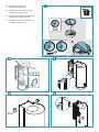
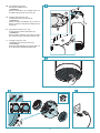
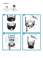
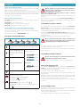
EN - Hood fastening (1-3-4-5);
Check valve installation (2);
ISLAND/WALL:
Remove metal lters (A), Assemble active car-
bon lters (B). Electrical connections (C).
FR - Fixation de la hotte (1-3-4-5);
Installation du clapet anti-retour (2);
ISLAND/WALL:
Retirer les ltres métalliques (A), monter les
ltres au charbon actif (B). Branchements élec-
triques (C).
ES - Fijación de la campana (1-3-4-5);
Instalación de la válvula antirretorno (2);
ISLAND/WALL:
Quite los ltros metálicos (A), monte los ltros
de carbón activo (B). Conexiones eléctricas (C).
IT - Fissaggio cappa (1-3-4-5);
Installazione valvola di non ritorno (2).
ISOLA/PARETE:
Rimuovere ltri metallici (A), montare ltri car-
bone attivo (B). Collegamenti elettrici (C).
B C

12
V3
V3
A
1
2
3
S
C
C
1
2
1
E
V3
A
B
S
2
3 4
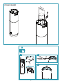
OPTIONAL

13
ENGLISH
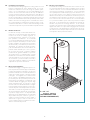
SAFETY INSTRUCTIONS
AND WARNINGS
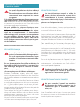
Installation operations are to be carried
out by skilled and qualied installers in ac-
cordance with the instructions in this book-
let and in compliance with the regulations
in force.
DO NOT use the hood if the power supply cable
or other components are damaged: disconnect
the hood from the electrical power supply and con-
tact the Dealer or an authorised Servicing Dealer for
repairs.
Do not modify the electrical, mechanical or func-
tional structure of the equipment.
Do not personally try to carry out repairs or re-
placements. Interventions carried out by incom-
petent and unauthorised persons can cause seri-
ous damage to the unit or physical and personal
harm, not covered by the Manufacturer's warran-
ty.
WARNINGS FOR THE INSTALLER
TECHNICAL SAFETY
Before installing the hood, check the in-
tegrity and function of each part. Should
anomalies be noted, do not proceed with
installation and contact the Dealer.
Do NOT install the hood if an aesthetic (or cos-
metic) defect has been detected. Put it back into
its original package and contact the dealer.
No claim can be made for aesthetic (or cosmetic)
defects once it has been installed.
During installation, always use personal protective
equipment (e.g.: Safety shoes) and adopt prudent
and proper conduct.
The installation kit (screws and plugs) supplied with
the hood is only to be used on masonry walls: in case
of installation on walls of a dierent material, assess
other installation options keeping in mind the type
of wall surface and the weight of the hood (indicated
on page 2).
Keep in mind that installations with dierent types of
fastening systems from those supplied, or which are
not compliant, can cause electrical and mechanical
seal danger.
Do not install the hood outdoors and do not expose
it to atmospheric elements (rain, wind, etc.).
ELECTRICAL SAFETY
The electrical system to which the hood is
to be connected must be in accordance
with local standards and supplied with
earthed connection in compliance with safety
regulations in the country of use. It must also
comply with European standards regarding radio
antistatic properties.
Before installing the hood, check that the electrical
mains power supply corresponds with what is report-
ed on the identication plate located inside the hood.
The socket used to connect the installed equipment
to the electrical power supply must be within reach:
otherwise, install a mains switch to disconnect the
hood when required.
Any changes to the electrical system must be carried
out by a qualied electrician.
The maximum length of the ue fastening screws
(supplied by the manufacturer) must be 1/2" (13 mm).
Use of non-compliant screws with these instructions
can lead to danger of an electrical nature.
Do not try to solve the problem yourself in the event
of equipment malfunction, but contact the Dealer or
an authorised Servicing Department for repairs.
When installing the hood, disconnect
the equipment by removing the plug or
switching o the main switch.
FUMES DISCHARGE SAFETY
Do no connect the equipment to discharge
pipes of fumes produced from combustion
(for example boilers, replaces, etc.).
Before installing the hood, ensure that all standards in
force regarding discharge of air out of the room have
been complied with.

14
USER WARNINGS
These warnings have been drawn up for
your personal safety and those of others.
You are therefore kindly asked to read the
booklet carefully in its entirety before using the
or cleaning the equipment.
The Manufacturer declines all responsibility for
any damage caused directly, or indirectly, to per-
sons, things and pets as a consequence of failing
to comply with the safety warnings indicated in
this booklet.
It is imperative that this instructions booklet is
kept together with the equipment for any future
consultation.
If the equipment is sold or transferred to another per-
son, make sure that the booklet is also supplied so
that the new user can be made aware of the hood's
operation and relative warnings.
After the stainless steel hood has been installed, it
will need to be cleaned to remove any residues re-
maining from the protection adhesive as well as any
grease and oil stains which, if not removed, can cause
irreversible damage to the hood surface. To properly
clean the unit, the manufacturer recommends using
the supplied moist wipes, which are also available
sold separately.
Insist on original spare parts.
INTENDED USE
The equipment is solely intended to be used to
extract fumes generated from cooking food in
non-professional domestic kitchens: any other
use is improper. Improper use can cause damage
to persons, things, pets and exempts the Manu-
facturer from any liability.
The equipment can be used by children over the age
of 8 and by persons with reduced physical, sensory
and mental abilities, or with no experience or knowl-
edge, as long as they do so under supervision or after
having received relative instructions regarding safe
use of the equipment and understanding of the dan-
gers connected to it.
Children are not to play with the equipment. Clean-
ing and maintenance by the user must not be carried
out by children without supervision.
USE AND CLEANING WARNINGS
Before cleaning or carrying out mainte-
nance operations, disconnect the equip-
ment by removing the plug or switching
o the main switch.
Do not use the hood with wet hands or bare feet.
Always check that all electrical parts (lights, extractor
fan) are o when the equipment is not being used.
The maximum overall weight of any objects placed
or hung (if applicable) on the hood must not exceed
3lb 5 oz (1.5 Kg).
Always supervise the cooking process during the use
of deep-fryers: Overheated oil can catch re.
Do not leave open, unattended ames under the
hood.
Do not prepare food over an open ame under the
hood.
Never use the hood without the metal anti-grease
lters: in this case, grease and dirt will deposit in the
equipment and compromise its operation.
Accessible parts of the hood can be hot when used at
the same time as the cooking appliances.
Do not carry out any cleaning operations when parts
of the hood are still hot.
There can be a risk of re if cleaning is not carried out
according to the instructions and products indicated
in this booklet.
Disconnect the main switch when the equipment is
not used for long periods of time.
If other appliances that use gas or other fu-
els are being used at the same time (boiler,
stove, replaces, etc.), make sure the room
where the fumes are discharged is well-ven-
tilated, in compliance with the local regula-
tions.

15
ENGLISH
INSTALLATION
only intended for qualied personnel
Before installing the hood, carefully read the chapter 'SA-
FETY INSTRUCTIONS AND WARNINGS'.
TECHNICAL FEATURES
The technical specications are exhibited on the labels located inside
the hood.
POSITIONING
The minimum distance between the highest part of the cooking
equipment and the lowest part of the hood is indicated in the in-
stallation instructions.
Generally, when the hood is placed over gas cookers, the distance must
be at least 65 cm (25.6''). However, according to an interpretation of
standard EN60335-2-31 dated 11-07-2002 of TC61 (sub-clause 7.12.1
meeting 15 agenda item 10.11), the minimum distance between the
cooker and lower part of the hood can be reduced to the quota report-
ed in the installation instructions.
Should the instructions for the gas cooker specify a greater distance,
this must be taken into consideration.
Do not install the hood outdoors and do not expose it to outdoor envi-
ronment (rain, wind, etc.).
ELECTRICAL CONNECTION
(only intended for qualied personnel)
Disconnect the equipment from electrical mains power
supply before carrying out any operations on the hood.
Ensure that the wires inside the hood are not disconnected
or cut:
in the event of damage, contact your nearest Servicing Depart-
ment.
Refer to qualied personnel for electrical connections.
Connection must be carried out in compliance with the provisions
of law in force.
Before connecting the hood to the electrical mains power supply,
check that:
• voltage supply corresponds with what is reported on the data plate
located inside the hood;
• the electrical system is compliant and can withstand the load (see
the technical specications located inside the hood);
• the power supply plug and cable do not come into contact with
temperatures exceeding 158°F (70 °C);
• the power supply system is eectively and properly connected to
earth in compliance with regulations in force;
• the socket used to connect the hood is within reach.
In case of:
• devices tted with cables without a plug: the type of plug to use is
a ''standardised'' one. The wires must be connected as follows: yel-
low-green for earthing, blue for neutral and brown for the phase. The
plug must be connected to an adequate safety socket.
• xed equipment not provided with a power supply cable and plug,
or any other device that ensures disconnection from the electrical
mains, with an opening gap of the contacts that enables total dis-
connection in overvoltage category III conditions.
Said disconnection devices must be provided in the mains power
supply in compliance with installation regulations.
The yellow/green earth cable must not be cut o by the switch.
The Manufacturer declines all responsibility for failure to comply with
the safety regulations.
FUMES DISCHARGE
EXTERNAL EXHAUST HOOD SUCTION
In this version the fumes and vapours are discharged
outside through the exhaust pipe.
To this end, the hood outlet tting must be connected
via a pipe, to an external output.
The outlet pipe must have:
• a diameter not less than that of the hood tting.
• a slight slope downwards (drop) in the horizontal sections to prevent
condensation from owing back into the motor.
• the minimum required number of bends.
• the minimum required length to avoid vibrations and reduce the
suction performance of the hood.
You are required to insulate the pipes if it passes through cold envi-
ronments.
In the presence of motors with 800m
3
/h or higher, a check valve is
present to prevent external air owing back.
HOOD WITH INTERNAL RECIRCULATION FILTERING
In this model, the air passes through the charcoal lters
to be puried and recycled in the environment.
Ensure that the active carbon lters are assembled into
the hood, if not, install them as indicated in the assem-
bly instructions.
In this version the check valve must not be assembled: remove
it if it is on the air outlet tting of the motor.
ASSEMBLY INSTRUCTIONS
only intended for qualied personnel
The hood can be installed in various congurations.
The generic assembly steps apply to all installations; for
each case, follow the specic steps provided for the re-
quired installation.

16
MAINTENANCE
Before cleaning or carrying out maintenance operations,
disconnect the equipment by removing the plug or
switching o the main switch.
Do not use detergents containing abrasive, acidic or corrosive
substances or abrasive cloths.
Regular maintenance guarantees proper operation and performance
over time.
Special attention is to be paid to the metal anti-grease lters : fre-
quent cleaning of the lters and their supports ensures that no amma-
ble grease is accumulated.
CLEANING OF EXTERNAL SURFACES
You are advised to clean the external surfaces of the hood at least once
every 15 days to prevent oily substances and grease from sticking to
them. To clean the brushed stainless steel hood, the Manufacturer rec-
ommends using "Magic Steel" wipes.
Alternatively and for all the other types of surfaces, it can be cleaned
using a damp cloth, slightly moistened with mild, liquid detergent or
denatured alcohol.
Complete cleaning by rinsing well and drying with soft cloths.
Do not use too much moisture or water around the push
button control panel and lighting devices in order to pre-
vent humidity from reaching electronic parts.
The glass panels can only be cleaned with specic, non-corrosive or
non-abrasive detergents using a soft cloth.
The Manufacturer declines all responsibility for failure to comply with
these instructions.
CLEANING OF INTERNAL SURFACES
Do not clean electrical parts, or parts related to the motor
inside the hood, with liquids or solvents.
For the internal metal parts, see the previous paragraph.
METAL ANTI-GREASE FILTERS
It is advised to frequently wash the metal lters (at least once a
month) leaving them to soak in boiling water and cleaning solution for
1 hour, taking care not to bend them.
Do not use corrosive, acid or alkaline detergents.
Rinse them well and wait for them to be completely dry before reas-
sembling them.
Washing in a dishwasher is permitted, however, it may cause the lter
material to darken: to reduce the possibility of this problem from hap-
pening, use low-temperature washes 131°F (55°C max.).
To extract and insert the metal anti-grease lters see the assembly in-
structions.
ACTIVE CARBON FILTERS
These lters retain the odours in the air that passes through them. The
puried air is recirculated into the environment.
The active carbon lters must be replaced on average every 3-4 months
under normal conditions of use.
See assembly instructions to replace the active carbon lters.
OPERATION
WHEN TO TURN ON THE HOOD?
Switch on the hood at least one minute before starting to cook to direct
fumes and vapours towards the suction surface.
After cooking, leave the hood operating until complete extraction of all
vapours and odours. By means of the Timer function, it is possible to set
auto switch-o function which will allow the hood to turn o automat-
ically after 15 minutes of operation.
WHICH SPEED IS TO BE SELECTED?
1st speed: maintains the circulation of clean air with low electricity
consumption.
2nd speed: normal conditions of use.
3rd speed: presence of strong odours and vapours.
4th speed: rapid disposal of odours and vapours.
WHEN SHOULD THE FILTERS BE WASHED OR REPLACED?
The metal lters must be cleaned every 30 hours of operation.
The active carbon lters must be replaced every 3-4 months, depend-
ing on the use of the hood.
For further details see the “MAINTENANCE” chap.
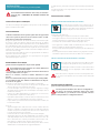
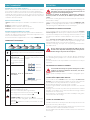
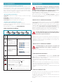
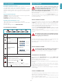
ELECTRONIC PUSHBUTTON PANEL
Motor ON/OFF
Upon start-up, the speed is that stored at the previous op-
eration.
Increase speed from 1 to 4
Speed 4 is only active for a
few minutes, then speed 3
activates.
The speeds are indicated by
the LEDs on the keys:
Speed 1
Speed 2
Speed 3
only version:
Speed 4
("+" LED ashing)
Reduce speed from 4 to 1
Light on/o
TIMER (red LED ashing)
Auto switch-o after 15 min.
The function deactivates (red LED o) if:
- The TIMER key ( ) is pressed again.
- The ON/OFF key ( ) is pressed.
FILTER ALARM (red LED steady on with ( ) o)
Anti-grease lter maintenance after approximately 30 hours
of operation.
Press ( ) the meter for 3 seconds to reset.

17
ENGLISH
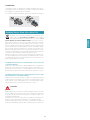
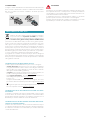
LIGHTING
The range hood is equipped with high eciency, low consumption
LED spotlights with an extremely long life-span under normal use con-
ditions.
Should the LED spotlight need to be replaced, proceed as shown in
the gure.
12V
3
1
2
DISPOSAL AFTER END OF USEFUL LIFE
The crossed-out trash or refuse bin symbol on the appliance
means that the product is WEEE, i.e. “Waste electrical and
electronic equipment'', accordingly it must not be disposed
of with regular unsorted waste (i.e. with ''mixed household waste''),
but it must be disposed of separately so that it can undergo specic
processing for its re-use, or a specic treatment, to remove and safely
dispose of any substances that may be harmful to the environment and
remove the raw materials that can be recycled. Proper disposal of these
products contributes to saving valuable resources and avoid potential
negative eects on personal health and the environment, which may
be caused by inappropriate disposal of waste.
You are kindly asked to contact your local authorities for further infor-
mation regarding the designated waste collection points nearest to
you. Penalties for improper disposal of such waste can be applied in
compliance with national regulations.
INFORMATION ON DISPOSAL IN EUROPEAN UNION COUNTRIES
The EU WEEE Directive was implemented dierently in each country,
accordingly, if you wish to dispose of this appliance we suggest con-
tacting your local authorities or dealer to nd out what the correct
method of disposal is.
INFORMATION ON DISPOSAL IN NONEUROPEAN UNION COUN
TRIES
The crossed-out trash or refuse bin symbol is only valid in the European
Union: if you wish to dispose of this appliance in other countries, we
suggest contacting your local authorities or dealer to nd out what the
correct method of disposal is.
WARNING!
The Manufacturer reserves the right to make changes to the equip-
ment at any time and without prior notice. Printing, translation and
reproduction, even partial, of this manual are bound by the Manufac-
turer's authorisation.
Technical information, graphic representations and specications in
this manual are for information purposes and cannot be divulged.
This manual is written in Italian. The Manufacturer is not responsible for
any transcription or translation errors.

18
CONSIGNES DE SÉCURITÉ
ET MISES EN GARDE
Le travail d'installation doit être eectué
par des installateurs compétents et quali-
és, conformément aux indications du pré-
sent manuel et en respectant les normes
en vigueur.
Si le câble d'alimentation ou d’autres composants
sont endommagés, la hotte NE doit PAS être utili-
sée: débrancher la hotte de l'alimentation électrique
et contacter le revendeur ou un Centre d’Assistance
technique agréé pour la réparation.
Ne pas modier la structure électrique, méca-
nique et fonctionnelle de l'appareil.
Ne pas tenter d'eectuer soi-même des répara-
tions ou des remplacements : les interventions
eectuées par des personnes non compétentes
et non qualiées peuvent provoquer des dom-
mages, éventuellement très graves, à des choses
et/ou à des personnes, non couverts par la garan-
tie du Fabricant.
MISES EN GARDE POUR L’INSTALLATEUR
SÉCURITÉ TECHNIQUE
Avant d'installer la hotte, contrôler l'inté-
grité et la fonctionnalité de chaque partie:
en cas de constatation d'anomalies, ne pas
procéder à l'installation et contacter le Re-
vendeur.
En cas de constatation d'un défaut esthétique, la
hotte NE doit PAS être installée; la remettre dans
son emballage d’origine et contacter le Reven-
deur.
Après son installation, aucune réclamation ne
sera acceptée pour des défauts esthétiques.
Pendant l'installation, toujours utiliser des équipe-
ments de protection individuelle (ex.: des chaussures
de sécurité) et adopter un comportement prudent et
correct.
Le kit de xation (vis et chevilles) fourni avec la hotte
est utilisable uniquement sur des murs en maçonne-
rie: s'il faut installer la hotte sur des murs de maté-
riau diérent, évaluer d’autres systèmes de xation en
tenant compte de la résistance du mur et du poids de
la hotte (indiqué à la page 2).
Tenir compte du fait que l'installation avec des sys-
tèmes de xation diérents de ceux fournis ou non
conformes peut comporter des risques de nature
électrique et de tenue mécanique.
Ne pas installer la hotte à l’extérieur et ne pas l’expo-
ser à des agents atmosphériques (pluie, vent, etc.).
SÉCURITÉ ÉLECTRIQUE
Le circuit électrique, auquel est reliée la
hotte, doit être aux normes et muni d’un
raccordement à la terre, conformément
aux normes de sécurité du pays d’utilisation; il
doit en outre être conforme aux normes euro-
péennes sur l'antiparasite radio.
Avant d'installer la hotte, s'assurer que la tension du
secteur correspond à celle reportée sur la plaque qui
se trouve à l'intérieur de la hotte.
La prise utilisée pour le branchement électrique doit
être facilement accessible avec l'appareil installé: si
cela n'était pas possible, prévoir un interrupteur gé-
néral pour déconnecter la hotte en cas de besoin.
Toute modication de l'installation électrique devra
être uniquement eectuée par un électricien qualié.
La longueur maximum de la vis de xation de la che-
minée (fournie par le fabricant) est de 1/2" (13 mm).
L'utilisation de vis non conformes avec les présentes
instructions peut comporter des risques de nature
électrique.
En cas de dysfonctionnements de l'appareil, ne pas
tenter de résoudre personnellement le problème,
mais contacter le revendeur ou un Centre d'Assis-
tance agréé pour la réparation.
Pendant l'installation de la hotte, débran-
cher l'appareil en retirant la prise ou en
agissant sur l'interrupteur général.
SÉCURITÉ ÉVACUATION DES FUMÉES
Ne pas raccorder l'appareil aux conduits
d'évacuation des fumées produites par la
combustion (par ex. chaudières, chemi-
nées, etc.)
Avant l'installation de la hotte, s'assurer que toutes
les normes en vigueur sur l’évacuation de l'air à l'exté-
rieur de la pièce sont respectées.

19
FRANÇAIS
MISES EN GARDE POUR L'UTILISATEUR
Ces mises en garde ont été rédigées pour
votre sécurité et pour celle d'autrui, nous
vous prions donc de lire attentivement
toutes les parties de ce manuel avant d'utiliser
l'appareil ou de le nettoyer.
Le fabricant décline toute responsabilité pour
d’éventuels dommages, directs ou indirects, pou-
vant être causés aux personnes, aux choses et
aux animaux domestiques, suite au non-respect
des mises en garde de sécurité indiquées dans ce
manuel.
Il est très important que ce manuel d'instructions
soit conservé avec l'appareil pour toute consulta-
tion future.
Si l'appareil devait être vendu ou transféré à une autre
personne, s'assurer que le manuel soit remis avec ce-
lui-ci, de manière à ce que le nouvel utilisateur puisse
connaître le fonctionnement de la hotte et des mises
en garde relatives.
Après l'installation des hottes en acier inox, il est né-
cessaire d'eectuer le nettoyage de celles-ci pour re-
tirer les résidus de colle de la protection et les taches
éventuelles de graisse et d'huile qui, si on ne les en-
lève pas, peuvent être cause de détérioration irréver-
sible de la surface de la hotte. Pour cette opération,
le fabricant conseille d'utiliser les serviettes fournies,
disponibles même à l'achat.
Exiger des pièces de rechange originales.
DESTINATION D'UTILISATION
L'appareil est destiné, seulement et exclusive-
ment, pour l'aspiration de fumées générées par
la cuisson d'aliments en milieu domestique, non
professionnel: toute autre utilisation diérente
de celle-ci est impropre et peut provoquer des
dommages à des personnes, choses et animaux
domestiques, et dégage le Fabricant de toute res-
ponsabilité.
L'appareil peut être utilisé par des enfants de plus
de 8 ans et des personnes ayant des capacités phy-
siques, sensorielles ou mentales réduites, ou dépour-
vues d'expérience ou de connaissances nécessaires,
pourvu qu’ils soient sous surveillance ou bien après
qu’ils aient reçu les instructions relatives à une utilisa-
tion sûre de l'appareil et qu’ils aient compris les dan-
gers correspondants.
Les enfants ne doivent pas jouer avec l'appareil. Le
nettoyage et la maintenance destinés à être eectués
par l'utilisateur ne doivent pas être eectués par des
enfants sans surveillance.
MISES EN GARDE POUR L'UTILISATION
ET LE NETTOYAGE
Avant de procéder à toute opération de
nettoyage ou d'entretien, désactiver l'ap-
pareil en enlevant la che ou en agissant
sur l'interrupteur général.
Ne pas utiliser la hotte avec les mains mouillées ou les
pieds nus.
Contrôler toujours que toutes les parties électriques
(lumières, aspirateur) soient éteintes lorsque l'appa-
reil n'est pas utilisé.
Le poids maximum total d'éventuels objets position-
nées ou suspendus (où c'est prévu) sur la hotte ne
doit pas dépasser 3lb 5 oz (1,5 kg).
Contrôler les friteuses pendant l'utilisation: l'huile sur-
chauée pourrait s'enammer.
Ne pas allumer de ammes nues sous la hotte.
Ne pas cuisiner avec une amme nue sous la hotte.
Ne jamais utiliser la hotte sans les ltres métalliques
anti-graisse ; dans ce cas, la graisse et la saleté se
déposeraient dans l'appareil et compromettrait son
fonctionnement.
Des parties accessibles de la hotte peuvent être
chaudes si elles sont utilisées avec des appareils de
cuisson.
Ne pas eectuer d’opérations de nettoyage si des
parties de la hotte sont encore chaudes.
Si le nettoyage n'est pas mené conformément aux
modalités et avec les produits indiqués dans le pré-
sent manuel, un risque d’incendie est possible.
Couper l'interrupteur général si l'appareil n'est pas
utilisé pendant de longues périodes.
En cas d'utilisation simultanée avec
d'autres éléments (chaudières, poêles, che-
minées, etc.) alimentés au gaz ou avec
d'autres combustibles, pourvoir à une ven-
tilation adéquate du local où s'eectue
l'aspiration de la fumée, conformément
aux normes en vigueur.

20
INSTALLATION
partie réservée uniquement à un personnel qualié
Avant d’eectuer l'installation de la hotte, lire attentive-
ment le chap. « CONSIGNES DE SÉCURITÉ ET MISES EN
GARDE».
CARACTÉRISTIQUES TECHNIQUES
Les données techniques de l'appareil sont reportées sur des étiquettes
placées à l'intérieur de la hotte.
POSITIONNEMENT
La distance minimum entre la partie la plus haute de l'appareil de
cuisson et la partie la plus basse de la hotte de cuisine est indi-
quée dans les instructions de montage.
En général, quand la hotte de cuisine est située au-dessus d'un plan
de cuisson à gaz, cette distance doit être d'au moins 65 cm (25,6'').
Cependant, sur la base d'une interprétation de la norme EN60335-2-31
du 11/07/2002 par le TC61 (sous-alinéa 7.12.1 session 15 point à l'ordre
du jour 10.11), la distance minimum entre le plan de cuisson et la partie
inférieure de la hotte peut être réduite à la hauteur indiquée dans les
instructions de montage.
Si les instructions de la table de cuisson au gaz spécient une distance
supérieure, il faut en tenir compte.
Ne pas installer la hotte à l’extérieur et ne pas l’exposer à des agents
atmosphériques (pluie, vent, etc.).
BRANCHEMENT ÉLECTRIQUE
(partie réservée uniquement à un personnel qualié)
Avant d'eectuer toute opération sur la hotte, débrancher
l'appareil du réseau électrique.
Veiller à ce que les ls électriques à l'intérieur de la hotte ne
soient pas débranchés ou coupés:
dans le cas contraire, contacter le Centre d'Assistance le plus
proche.
Pour le raccordement électrique contacter un personnel qualié.
Le raccordement doit être eectué conformément aux disposi-
tions de lois en vigueur.
Avant de raccorder la hotte au réseau électrique, contrôler que:
• la tension du secteur corresponde à celle reportée sur la plaque des
données qui se trouve à l'intérieur de la hotte;
• le circuit électrique soit aux normes et puisse supporter la charge
de l'appareil (voir la plaque des caractéristiques techniques située à
l'intérieur de la hotte);
• la che et le câble d'alimentation ne rentrent pas en contact avec
des températures supérieures à 158°F (70 °C);
• l’installation d'alimentation soit munie d'un raccordement à la terre
ecace et correct, conformément aux normes en vigueur;
• la prise utilisée pour le branchement soit facilement accessible, une
fois la hotte installée.
En cas d':
• appareils équipés d'un câble sans che: la che à utiliser doit être
du type «normalisé». Les ls doivent être raccordés de la manière
suivante: le l jaune-vert doit pour la mise à la terre, le l bleu pour
le neutre et le l marron pour la phase.
La che doit être raccordée à une prise de sécurité adéquate.
• appareil xe dépourvu de câble d'alimentation et de che ou d'un
autre dispositif qui assure la déconnexion du réseau, avec une dis-
tance d'ouverture des contacts permettant la déconnexion com-
plète dans les conditions de la catégorie de surtension III.
Ces dispositifs de déconnexion doivent être prévus dans le réseau
d'alimentation conformément aux règles d'installation.
Le câble de terre jaune/vert ne doit pas être interrompu par l'interrup-
teur.
Le Fabricant décline toute responsabilité si les normes de sécurité ne
sont pas respectées.
ÉVACUATION DES FUMÉES
HOTTE À ÉVACUATION EXTÉRIEURE ASPIRANTE
Dans cette version, les fumées et les vapeurs sont en-
voyées vers l'extérieur à travers un tuyau d'évacuation.
À cette n, le raccord de sortie de la hotte doit être rac-
cordé par un tuyau à une sortie extérieure.
Le tuyau de sortie doit avoir:
• un diamètre égal ou supérieur à celui du raccord de la hotte.
• une légère inclinaison vers le bas (chute) dans les tronçons horizon-
taux pour éviter que la condensation ne reue dans le moteur.
• un nombre de coudes réduit au minimum (pas plus de 3).
• une longueur de conduit réduite au minimum pour éviter toute vi-
bration et réduire la capacité aspirante de la hotte.
Il est nécessaire d'isoler la tuyauterie si elle passe par des endroits non
chaués.
Pour empêcher les retours d'air de l'extérieur, un clapet de non retour
est installé en présence des moteurs avec 800 m
3
/h ou supérieurs.
HOTTE À RECIRCULATION INTÉRIEURE FILTRANTE
Dans cette version, l'air passe à travers les ltres au char-
bon actif pour être purié et est recyclé dans la pièce.
Contrôler que les ltres au charbon actif soient montés
sur la hotte, sinon les appliquer comme indiqué dans
les instructions de montage.
Dans cette version, le clapet de non retour ne doit pas être mon-
té: le retirer s'il est présent sur le raccord de sortie de d'air du
moteur.
INSTRUCTIONS DE MONTAGE
partie réservée uniquement à un personnel qualié
La hotte peut être installée selon diverses congurations.
Les phases de montage génériques valent pour toutes
les installations; par contre, là où il est spécié, suivre les
phases correspondant à la conguration désirée.
La pagina sta caricando ...
La pagina sta caricando ...
La pagina sta caricando ...
La pagina sta caricando ...
La pagina sta caricando ...
La pagina sta caricando ...
La pagina sta caricando ...
La pagina sta caricando ...
La pagina sta caricando ...
La pagina sta caricando ...
La pagina sta caricando ...
La pagina sta caricando ...
La pagina sta caricando ...
La pagina sta caricando ...
La pagina sta caricando ...
La pagina sta caricando ...
-
 1
1
-
 2
2
-
 3
3
-
 4
4
-
 5
5
-
 6
6
-
 7
7
-
 8
8
-
 9
9
-
 10
10
-
 11
11
-
 12
12
-
 13
13
-
 14
14
-
 15
15
-
 16
16
-
 17
17
-
 18
18
-
 19
19
-
 20
20
-
 21
21
-
 22
22
-
 23
23
-
 24
24
-
 25
25
-
 26
26
-
 27
27
-
 28
28
-
 29
29
-
 30
30
-
 31
31
-
 32
32
-
 33
33
-
 34
34
-
 35
35
-
 36
36


Falmec FDPLR15W5SS Guida utente
- Categoria
- Cappe da cucina
- Tipo
- Guida utente
in altre lingue
- English: Falmec FDPLR15W5SS User guide
- français: Falmec FDPLR15W5SS Mode d'emploi
- español: Falmec FDPLR15W5SS Guía del usuario
Documenti correlati
-
Falmec Polar Manuale del proprietario
-
Falmec FPAFX30W6SS Manuale del proprietario
-
Falmec Zenith 180 Istruzioni per l'uso
-
-
Falmec FPDPR36I9SS Manuale del proprietario
-
-
-
-
-
