Viessmann 6366 Manuale del proprietario
- Categoria
- Accessori per la preparazione del caffè
- Tipo
- Manuale del proprietario

6366
H0 Hängelampe mit Seilaufhängung,
LED weiß
H0 Light hanging with rope,
LED white
Bedienungsanleitung
Operation Manual
DE
1
Modellbauartikel, kein Spielzeug! Nicht geeignet für
Kinder unter 14 Jahren! Anleitung aufbewahren!
Model building item, not a toy! Not suitable for children
under the age of 14 years! Keep these instructions!
Ce n’est pas un jouet! Ne convient pas aux enfants de
moins de 14 ans! Conservez cette notice d’instructions!
Não é um brinquedo! Não aconselhável para menores
de 14 anos! Conservar o manual de instruções!
Modelbouwartikel, geen speelgoed! Niet geschikt voor
kinderen onder 14 jaar! Gebruiksaanwijzing bewaren!
Articolo di modellismo, non è un giocattolo! Non adat-
to a bambini al di sotto dei 14 anni! Conservare istruzioni
per l’uso!
Artículo para modelismo ¡No es un juguete! No reco-
mendado para menores de 14 años! Conserva las inst-
rucciones de servicio!
DE
EN
FR
NL
IT
ES
PT
1. Wichtige Hinweise
Bitte lesen Sie vor der ersten Anwendung des Produktes bzw.
dessen Einbau diese Bedienungsanleitung aufmerksam durch
und bewahren Sie diese auf. Sie ist Teil des Produktes.
1.1 Sicherheitshinweise
Vorsicht:
Verletzungsgefahr!
Aufgrund der detaillierten Abbildung des Originals bzw. der vorgese-
henen Verwendung kann das Produkt Spitzen, Kanten und abbruch-
gefährdete Teile aufweisen. Für die Montage sind Werkzeuge nötig.
Stromschlaggefahr!
Die Anschlussdrähte niemals in eine Steckdose einführen!
Verwendetes Versorgungsgerät (Transformator, Netzteil)
regelmäßig auf Schäden überprüfen. Bei Schäden am Ver-
sorgungsgerät dieses keinesfalls benutzen!
Alle Anschluss- und Montagearbeiten nur bei abgeschalteter
Betriebsspannung durchführen!
Ausschließlich nach VDE/EN gefertigte Modellbahntransfor-
matoren verwenden!
Stromquellen unbedingt so absichern, dass es bei einem
Kurzschluss nicht zum Kabelbrand kommen kann.
1.2 Das Produkt richtig verwenden
Dieses Produkt ist bestimmt:
- Zum Einbau in Modelleisenbahnanlagen und Dioramen.
- Zum Anschluss an einen Modellbahntransformator (z. B. Art.
5200) bzw. an eine Modellbahnsteuerung mit zugelassener
Betriebsspannung.
- Zum Betrieb in trockenen Räumen.
Jeder darüber hinausgehende Gebrauch gilt als nicht bestim-
mungsgemäß. Für daraus resultierende Schäden haftet der
Hersteller nicht.
1.3 Packungsinhalt überprüfen
Kontrollieren Sie den Lieferumfang auf Vollständigkeit:
- LED-Hängelampe
- 2 Seilaufhängungen
- Anleitung
2. Einleitung
Dieses Modell erzeugt durch die SMD-LED ein zum Modell pas-
sendes Licht. Stromaufnahme und Wärmeentwicklung sind sehr
gering. Die Lebensdauer der LED ist praktisch unbegrenzt, so dass
ein Wechsel des Leuchtmittels entfällt.

2
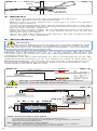
Diode und Widerstand nicht abschneiden!
Never cut o diode and resistor!
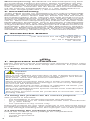
Abb. 2 Fig. 2
Fig. 3
braun
brown
Diode
diode
Widerstand
resistor
gelb / yellow +
10 – 16 V AC ~
14 – 24 V DC =
13 – 24 V
Digitalsignal
digital signal
–
(mit und ohne 5215 Powermodul)
(with and without 5215 power module)
Kabel
cables
Wand
wall
Abb. 1 Fig. 1
TIPP: Powermodul, Art. 5215
- Verhindert Flackern bei Wechselstrom.
- Annähernd doppelte Helligkeit gegenüber reinem
Wechselstrombetrieb.
TIP: Power module, item 5215
- Offers flicker-free lighting when using AC power.
- Nearly double brightness is possible.
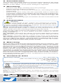
Sekundär
0-10-16 V~
16 V
Primär
230 V~
Gefertigt nach
VDE 0570
EN 61558
Lichttransformator
5200
Nur für trockene Räume
Primär 230 V 50 - 60 Hz
Sekundär max. 3,25 A52 VA
ta 25°CIP 40
10 V
0 V
viessmann
Powermodul 5215
T
E
ge bn
Braune Massebuchsen
nicht koppeln !
max. 24 V~
rt bn
zu den Decodern
5215
gelb
braun / brown
16 V~
z. B. / e. g. 5200
yellow
16 V~
3. Einbau
- Leuchte vorsichtig aus der Verpackung nehmen.
- Vor dem Einbau auf Funktion prüfen.
- Bohren Sie in eine Wand ein Loch (Ø 1,5 mm) zur Befes-
tigung des Hakens.
- In die gegenüberliegende Wand bohren Sie ein Loch (Ø 2
mm) zur Durchführung der Anschlusskabel sowie zur Befes-
tigung des zweiten Hakens.
- Führen Sie beide Kabel durch die Bohrungen und befes-
tigen Sie die Haken (Abb. 1). Die Kabel führen Sie durch die
Aussparung im Haken.
- Spannen Sie das Halteseil und fixieren Sie die beiden Enden
durch Knoten oder Klebstoff.
4. Anschluss
Vorsicht:
Widerstand und Diode an den Enden der Anschlussdrähte sind
für die Funktion erforderlich. Keinesfalls entfernen (Abb. 2)! Wi-
derstände nicht mit Isolationsmaterial umhüllen, da sonst keine
ausreichende Kühlung möglich ist!
Lassen Sie beim Anschließen der Kabel unterhalb des LED-
Modells eine Schleife von ca. 2 – 3 cm Länge, damit Sie die
Leuchte bei evtl. Arbeiten aus der Montagebohrung ziehen und
umlegen können.
Schließen Sie das LED-Modell an den Lichtausgang eines Mo-
dellbahntransformators (z. B. Art. 5200) an (Abb. 2 oder Abb. 3).
Gleichspannung: Verbinden Sie die Diode (rotes Bauteil mit
schwarzer Markierung) mit dem Plus-Pol des Netzteils, den
Widerstand mit dem Minus-Pol.
Abb. 3 Diode
diode Widerstand
resistor

3
1. Important information
Please read this manual completely and attentively before using
the product for the first time. Keep this manual. It is part of the
product.
1.1 Safety instructions
Caution:
Risk of injury!
Due to the detailed reproduction of the original and the in-
tended use, this product can have peaks, edges and break-
able parts. Tools are required for installation.
Electrical hazard!
Never put the connecting wires into a power socket! Regularly
examine the transformer for damage. In case of any damage,
do not use the transformer.
Make sure that the power supply is switched off when you
mount the device and connect the cables!
Only use VDE/EN tested special model train transformers
for the power supply!
The power sources must be protected to avoid the risk of
burning cables.
1.2 Using the product for its correct purpose
This product is intended:
- For installation in model train layouts and dioramas.
- For connection to an authorized model train transformer
(e. g. item 5200).
- For operation in dry rooms only.
Using the product for any other purpose is not approved and is
considered inappropriate. The manufacturer is not responsible
for any damage resulting from the improper use of this product.
1.3 Checking the package contents
Check the contents of the package for completeness:
- LED-light hanging
- 2 rope suspensions
- Manual
EN
Wechselspannung: Bei Betrieb mit Wechselspannung kann
es zu leichtem Flackern kommen. Daher empfehlen wir den
Betrieb mit dem Viessmann-Powermodul, Art. 5215 (Abb. 3).
Ein Powermodul ist ausreichend für ca. 100 LED-Leuchten
oder -Strahler. Verbinden Sie die Diode des Anschlusskabels
mit der braunen Ausgangsbuchse (+), den Widerstand mit
der roten Ausgangsbuchse (-) des Powermoduls.
5. Gewährleistung
Jeder Artikel wurde vor Auslieferung auf volle Funktionalität
geprüft. Der Gewährleistungszeitraum beträgt 2 Jahre ab
Kaufdatum. Tritt in dieser Zeit ein Fehler auf und Sie finden
die Fehlerursache nicht, nehmen Sie bitte Kontakt mit uns
auf ([email protected]). Senden Sie uns den
Artikel zur Kontrolle bzw. Reparatur bitte erst nach Rückspra-
che zu. Wird nach Überprüfung des Artikels ein Herstell- oder
Materialfehler festgestellt, wird er kostenlos instandgesetzt
oder ausgetauscht. Von der Gewährleistung und Haftung
ausgeschlossen sind Beschädigungen des Artikels sowie Fol-
geschäden, die durch unsachgemäße Behandlung, Nichtbe-
achten der Bedienungsanleitung, nicht bestimmungsgemäßen
Gebrauch, eigenmächtigen Eingriff, bauliche Veränderungen,
Gewalteinwirkung, Überhitzung u. ä. verursacht werden.
6. Technische Daten
Betriebsspannung: 10 – 16 V AC ~
(mit und ohne Art. 5215, Powermodul)
14 – 24 V DC =
13 – 24 V Digitalsignal
Stromaufnahme: ca. 10 mA

Viessmann
Modelltec
hnik GmbH
Bahnhofstraße 2a
D - 35116 Hatzfeld-Reddighausen
+49 6452 9340-0
www.viessmann-modell.de
Made in Europe
Entsorgen Sie dieses Produkt nicht über den (unsortierten)
Hausmüll, sondern führen Sie es der Wiederverwertung zu.
Do not dispose of this product through (unsorted) domestic
waste, supply it to recycling instead.
Subject to change without prior notice. No liability for mistakes and printing
errors.
You will find the latest version of the manual on the Viessmann website using
the item number.
Änderungen vorbehalten. Keine Haftung für Druckfehler und Irrtümer.
Die aktuelle Version der Anleitung finden Sie auf der Viessmann Homepage
unter der Artikelnummer.
92369
Stand 03/sw
03/2023
Ho/Kf
4
FR
2. Introduction
This model uses SMD LEDs to produce light matching the lamp
model. Low heat build-up and power input. Nearly unlimited
lifetime of the LEDs, so no more change is required.
3. Mounting
- Remove the lamp carefully from the package.
- Check function before mounting.
- Drill a hole (Ø 1.5 mm) into a wall for mounting the rope
suspension.
- Drill a hole (Ø 2 mm) into the opposite wall to insert the
connection cables and to fasten the second rope suspension.
- Insert the connection cables into the holes and fasten the
rope suspensions (fig. 1). Guide the cables through the
recess in the ropes.
- Tension the retaining rope and fasten the two ends with knots
or glue.
4. Connection
Caution:
Resistor and diode at the cables are needed for proper
function of the LED model. Never cut them off! Never cover
resistor or diode with insulation material, because they have
to be cooled by surrounding air!
While connecting the cables, leave a loop of about 2 – 3 cm
length below the LED model, so that you can pull and reverse the
LED model from the mounting hole during any work.
Connect the LED model to the lighting power output of a model
train transformer (e. g. item 5200) or power supply as shown
in fig. 2 and/or 3.
DC voltage: Connect the diode (red part with black marker)
with the plus pole of the power supply, the resistor with the minus
pole.
AC voltage: Operation with AC voltage could cause some flickering.
We recommend to use the Viessmann power module, item 5215,
which is sufficient for approx. 100 LED lamps or reflectors (fig. 3). Con-
nect the cable to the diode with the brown output socket, the resistor
with the red output socket of the power module.
5. Warranty
Each model is tested to its full functionality prior to delivery. The
warranty period is 2 years starting from the date of purchase.
Should a fault occur during this period please contact our service
department ([email protected]). Please send
the item to the Viessmann service department for checking and
repair only after consultation. If we find a material or production
fault to be the cause of the failure, the item will be repaired free
of charge or replaced. Expressively excluded from any warranty
claims and liability are damages of the item and consequential
damages due to inappropriate handling, disregarding the instruc
-
tions of this manual, inappropriate use of the model, unauthor-
ized disassembling, construction modifications and use of force,
overheating and similar.
6. Technical data
Operating voltage: 10 – 16 V AC ~
(with and without item 5215, power module)
14 – 24 V DC =
13 – 24 V digital signal
Operating current: ca. 10 mA
Points de collecte sur www.quefairedemesdechets.fr
À DÉPOSER
EN MAGASIN À DÉPOSER
EN DÉCHÈTERIE
OU
Cet modéle
se recycle
FR
-
 1
1
-
 2
2
-
 3
3
-
 4
4


Viessmann 6366 Manuale del proprietario
- Categoria
- Accessori per la preparazione del caffè
- Tipo
- Manuale del proprietario
in altre lingue
- English: Viessmann 6366 Owner's manual
- Deutsch: Viessmann 6366 Bedienungsanleitung
Documenti correlati
-
Viessmann 6365 Manuale del proprietario
-
-
-
-
-
Viessmann 1397 Manuale del proprietario
-
-
-
-
Viessmann 6338 Manuale del proprietario