
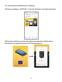
PREMIUM SERIES
EV Wallbox Charging Station
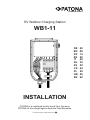
WB1-11
PATONA PRODUCTS ARE MADE WITH
PATONA is a registered quality brand from Germany.
PATONA ist eine eingetragene deutsche Qualitätsmarke.
DE / EN / FR / ES / IT / NL / SV / CS / PL / HR / SR
MANUAL
DE 03
EN 12
FR 21
ES 30
IT 39
NL 48
SV 57
CS 66
PL 75
HR 84
SR 93


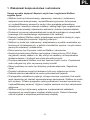
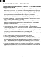
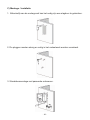
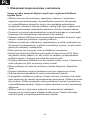
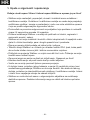
1. Sicherheits- und Warnhinweise
Achtung Hochspannung! Die Eingangs- und Ausgangsspannung der
Wallbox ist lebensgefährlich!
»Die Wallbox darf nur von autorisiertem und qualiziertem Fachpersonal zer-
legt, repariert, geöffnet und installiert werden. Autorisiertes und qualiziertes
Fachpersonal sind Personen, welche über zertizierte Fähigkeiten und Kennt-
nisse in Bezug auf Installation und Betrieb dieser Art elektrischer Anlagen
verfügen und entsprechende Sicherheitsschulungen erhalten haben.
»Der Hersteller übernimmt keine Haftung für Folgen, die sich aus der unquali-
zierten und/oder unsachgemäßen Nutzung und/oder Installation ergeben.
»Bei der Installation einer Wallbox müssen alle lokalen, regionalen und natio-
nalen Vorschriften und Gesetze eingehalten werden.
»Die Wallbox darf nicht in der Nähe explosiver oder brennbarer Materialien so-
wie in der Nähe von Chemikalien, Dämpfen und anderen gefährlichen Subs-
tanzen und Gegenständen installiert und betrieben werden.
»Kinder sind von der Wallbox und dem Zubehör fernzuhalten.
»Die technische Ausführung der Wallbox entspricht der Schutzklasse IP54.
Dennoch sollte darauf geachtet werden, dass diese nicht direktem Regen und
Unwetter ausgesetzt ist.
»Der Ladeanschluss der Wallbox muss stets sauber und trocken sein. Die Rei-
nigung darf nur mit einem trockenen Tuch erfolgen.
»Der Sockelkern darf beim Einschalten nicht berührt werden. Lebensgefahr!
»Hybridfahrzeuge dürfen nur geladen werden, wenn der Motor aus ist.
»Das Fahrzeug darf während des Ladevorganges nicht bewegt werden.
»Bei einem Defekt, Rissen, starkem Abrieb, Auslaufen und/oder eigenartigen
Gerüchen sowie unerwartetem Verhalten darf die Wallbox nicht genutzt wer-
den. Tritt solch ein Fall auf, muss autorisiertes und qualiziertes Fachpersonal
verständigt/gerufen werden. Die Ausgangs- und Eingangsstromversorgung ist
umgehend zu trennen.
»Die Wallbox darf nur über eine geeignete Einrichtung zum Recycling von
Elektrogeräten entsorgt werden. Weitere Informationen können bei der ört-
lichen Gemeindeverwaltung erfragt werden.
DE
- 3 -

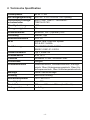
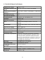
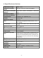
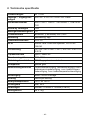
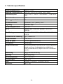
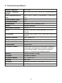
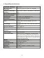
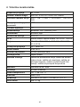
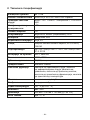
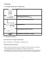
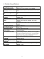
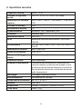
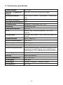
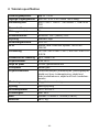
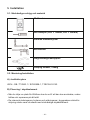
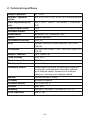
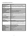
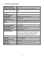
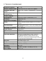
2. Technische Spezikation
Ladekapazität bis zu 11 KW
Ein-/Ausgangsleistung 400V AC ± 20% 50/60Hz 16A 3-phasig
Fehlerstrom-Leitungs-
schutzschalter
400V~ GB/T10963.1 / IEC60898-1
TGB1N-63 C40
Standby-Leistung <3W
Messgenauigkeit 1%
Kommunikation Bluetooth, WIFI (Optional), APP
Steuerung manuell, App
Benutzeroberäche LCD 3.5"
RFID Mikron Fare Collection System
ISO & IEC 14443A
Zertizierung CE / EN/IEC 61851-1:2017
EN/IEC 61851-21-2:2018
Ladeschnittstelle Typ 2, Kabel 5m
Schutzklassen IP54, IK10
Gehäuse Kunststoff PC940, verzinkter Stahl
Frontblende Hartglas
Schutzfunktionen Überstromschutz, Fehlerstromschutz, Erdungs-
schutz, Über-/Unterspannungsschutz, Über-/Un-
terfrequenzschutz, Über-/Untertemperaturschutz
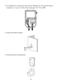
Montage Wand-/Säulenmontage
Kühlung natürliche Kühlung
Betriebstemperatur -30°C bis +55°C
Feuchtigkeit max. 95%
Produktabmessungen 320mm × 230mm × 100mm (L × W × H)
Nettogewicht ca. 5.1kg
- 4 -

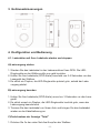
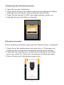
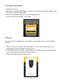
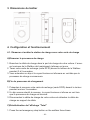
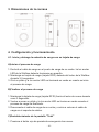
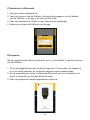
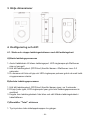
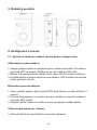
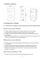
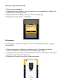
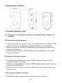
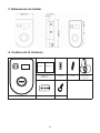
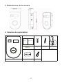
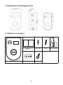
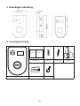
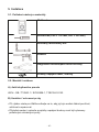
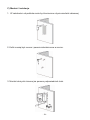
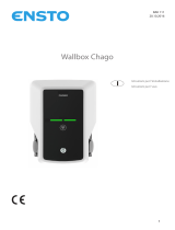
3. Gehäuseabmessungen
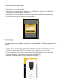
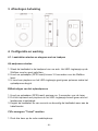
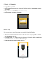
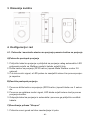
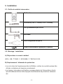
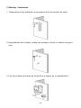
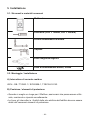
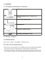
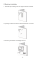
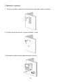
4. Konguration und Bedienung
4.1. Ladestation mit Ihrer Ladekarte starten und stoppen
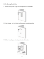
A) Ladevorgang starten
1. Stecken Sie das Ladekabel in den Ladeanschluss Ihres PKW. Die LED-
Ringleuchte an der Wallbox sollte nun gelb leuchten.
2. Halten Sie Ihre Ladekarte (RFID-Karte) innerhalb von 3-5 Sekunden vor das
Lesegerät der Wallbox.
3. Es ertönt ein Piepton, die LED-Ringleuchte pulsiert grün, sobald der Lade-
vorgang startet.
B) Ladevorgang beenden
1. Halten Sie Ihre Ladekarte (RFID-Karte) erneut ca. 3 Sekunden vor das Lese-
gerät.
2. Es ertönt erneut ein Piepton, die LED-Ringleuchte leuchtet grün, wenn der
Ladevorgang beendet wird.
3. Trennen Sie das Ladekabel von Ihrem Auto und bringen Sie das Ladekabel
wieder an der Kabelhalterung an.
C) Zurücksetzen der Anzeige "Total"
1. Drücken Sie 3x den roten Not-Aus-Knopf an der Wallbox.
- 5 -

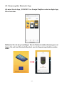
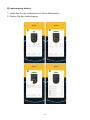
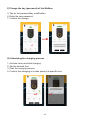
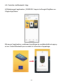
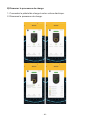
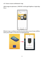
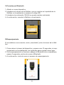
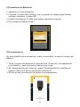
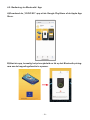
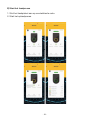
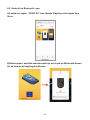
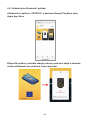
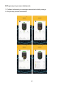
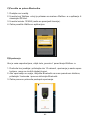
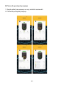
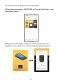
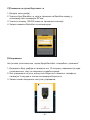
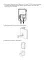
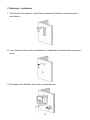
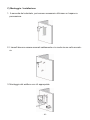
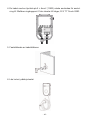
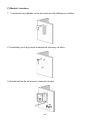
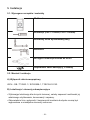
4.2. Steuerung über Bluetooth / App
A) Laden Sie die App „YOOZI EV“ im Google PlayStore oder im Apple App
Store herunter.
B) Starten Sie die App, bestätigen Sie die Datenschutzbestimmungen und
tippen Sie auf das Bluetooth-Symbol, um die Koppelungsfunktion aufzu-
rufen.
- 6 -

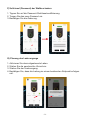
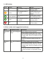
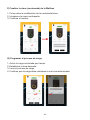
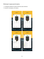
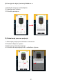
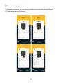
C) Verbindung über Bluetooth herstellen
1. Fügen Sie ein neues Gerät hinzu.
2. Tragen Sie die Nummer der Wallbox, welche auf dem Display der Wallbox
angezeigt wird in die App ein, oder scannen Sie den QR Code.
3. Tragen Sie das Passwort 123456 (kann später geändert werden) ein.
4. Verbinden Sie dann die Wallbox mit der App.
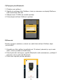
D) Kopplung herstellen
Ist eine Verbindung hergestellt, steht neben der Wallboxnummer „connectable“.
1. Tippen Sie auf die Gerätenummer und warten Sie ca. 10 Sekunden, die
Kopplung wird nun hergestellt, die nächsten Schritte können erfolgen.
2. Funktioniert die Kopplung nicht, schalten Sie bitte Bluetooth Ihres Smart-
phone aus, warten Sie 3 Sekunden und aktivieren Sie Bluetooth wieder.
3. Starten Sie dann den Verbindungsvorgang erneut.
- 7 -

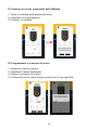
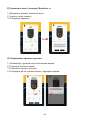
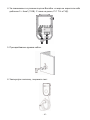
E) Ladevorgang starten
1. Verbinden Sie die Ladepistole mit Ihrem Elektroauto.
2. Starten Sie den Ladevorgang.
- 8 -

F) Schlüssel (Passwort) der Wallbox ändern
1. Tippen Sie auf die Passwort-/Schlüsselmodizierung.
2. Tragen Sie das neue Passwort ein.
3. Bestätigen Sie die Änderung.
G) Planung des Ladevorgangs
1. Aktivieren Sie das zeitgesteuerte Laden.
2. Stellen Sie die gewünschte Uhrzeit ein.
3. Starten Sie den Ladevorgang.
4. Bestätigen Sie, dass die Ladung zu einem bestimmten Zeitpunkt erfolgen
soll.
- 9 -

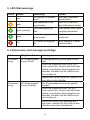
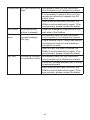
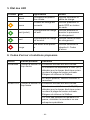
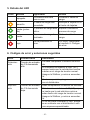
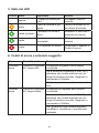
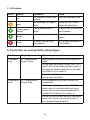
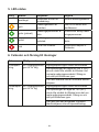
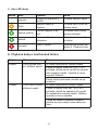
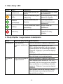
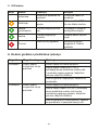
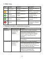
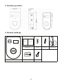
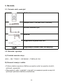
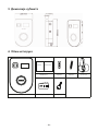
5. LED-Statusanzeige
Farbe Status Bedeutung Aktion
aus Die Wallbox ist einsatz-
bereit.
Bitte das Ladekabel
anschließen.
gelb Das Ladekabel ist an-
geschlossen.
Bitte RFID-Karte an
den Kartenleser halten.
grün (pulsiert) Der Ladevorgang ist
aktiv.
Bitte warten oder Lade-
vorgang abbrechen.
grün Der Ladevorgang ist ab-
geschlossen.
Bitte das Ladekabel
entfernen.
rot Ein Fehler ist aufgetre-
ten.
Bitte Kapitel 6. Fehler-
codes prüfen.
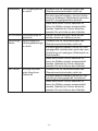
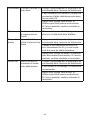
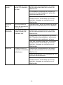
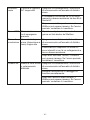
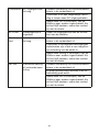
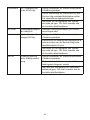
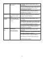
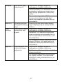
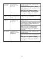
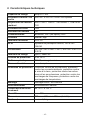
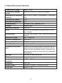
6. Fehlercodes und Lösungsvorschläge
Fehler Möglicher Grund Lösungen
Überspan-
nung
AC-Eingangsspan-
nung zu hoch
Eingangsspannung muss geprüft wer-
den.
Wenn die Spannung über 264V (AC)
liegt, warten Sie, bis sich das Stromnetz
wieder im normalen Spannungsbereich
bendet. Schalten Sie die Wallbox aus
und wieder ein.
Besteht der Fehler weiterhin, wenden Sie
sich bitte an den Händler.
Unterspan-
nung
AC-Eingangsspan-
nung zu niedrig
Die Eingangsspannung muss geprüft
werden.
Wenn die Spannung unter 140 (AC)
liegt, warten Sie, bis sich das Stromnetz
wieder im normalen Spannungsbereich
bendet. Schalten Sie die Wallbox aus
und wieder ein.
Wenn der Fehler nicht behoben wer-
den kann, wenden Sie sich bitte an den
Händler oder einen Fachbetrieb.
- 10 -

Überstrom AC-Eingangsstrom
zu hoch
Schalten Sie im Verteilerschrank den
Überstromschutzschalter sofort ab.
Es muss geprüft werden, ob eine Verbin-
dung mit niedrigem Widerstand zwischen
zwei AC-Ausgangsdrähten besteht.
Nach dem dieser Fehler behoben ist,
kann die Wallbox wieder eingeschaltet
werden. Besteht der Fehler weiterhin,
wenden Sie sich bitte an den Händler.
EPO-Fehler Not-Aus-Knopf ist
gedrückt
Ziehen Sie die Not-Aus-Taste an der
rechten Seite der Wallbox zurück.
Ableitungs-
fehler
Ableitungsstrom
(Erdungsableitung)
zu hoch
Schalten Sie im Verteilerschrank den
Überstromschutzschalter sofort ab.
Es muss geprüft werden, ob die AC-Aus-
gangsgeräte unterbrochen sind oder eine
Verbindung mit niedrigem Widerstand zur
Erde besteht.
Nach dem dieser Fehler behoben ist,
kann die Wallbox wieder eingeschaltet
werden. Besteht der Fehler weiterhin,
wenden Sie sich bitte an den Händler.
NE-Fehler Erdung inkorrekt
oder Anschluss
fehlerhaft
Schalten Sie im Verteilerschrank den
Überstromschutzschalter sofort ab.
Es muss geprüft werden, ob die AC-Ver-
kabelung ordnungsgemäß funktioniert.
Nach dem dieser Fehler behoben ist,
kann die Wallbox wieder eingeschaltet
werden. Besteht der Fehler weiterhin,
wenden Sie sich bitte an den Händler.
- 11 -

EN
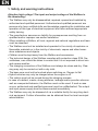
1. Safety and warning instructions
Attention high voltage! The input and output voltage of the Wallbox is
life-threatening!
»The Wallbox may only be disassembled, repaired, opened and installed by
authorized and qualied personnel. Authorized and qualied personnel are
persons who have certied skills and knowledge regarding the installation and
operation of this type of electrical equipment and have received appropriate
safety training.
»The manufacturer assumes no liability for consequences resulting from un-
qualied and/or improper use and/or installation.
»When installing a Wallbox, all local, regional and national regulations and laws
must be observed.
»The Wallbox must not be installed and operated in the vicinity of explosive or
ammable materials or in the vicinity of chemicals, vapors and other hazar-
dous substances and objects.
»Children must be kept away from the Wallbox and accessories.
»The technical design of the Wallbox complies with protection class IP54. Ne-
vertheless, care should be taken to ensure that it is not exposed to direct rain
and severe weather.
»The charging connection of the Wallbox must always be clean and dry. Clea-
ning may only be carried out with a dry cloth.
»The base core must not be touched when switching on. Danger to life!
»Hybrid vehicles may only be charged when the engine is off.
»The vehicle must not be moved during the charging process.
»In case of a defect, cracks, strong abrasion, leakage and/or peculiar odors as
well as unexpected behavior, the Wallbox must not be used. If such a case
occurs, authorized and qualied personnel must be notied/called. The output
and input power supply must be disconnected immediately.
»The Wallbox may only be disposed of via a suitable facility for recycling elect-
rical equipment. Further information can be obtained from the local municipal
administration.
- 12 -

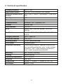
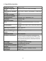
2. Technical specication
Charging capacity up to 11 KW
Input/output power 400V AC ± 20% 50/60Hz 16A 3-phase
Residual current circuit
breaker
400V~ GB / T10963.1 / IEC60898-1, TGB1N-63
C40
Standby power <3W
Measurement accuracy 1%
Communication Bluetooth, WIFI (Optional), APP
Control manual, App
User interface LCD 3.5"
RFID Mikron Fare Collection System, ISO & IEC
14443A
Certication CE / EN / IEC 61851-1:2017, EN / IEC 61851-21-
2:2018
Charging interface type 2, cable 5m
Protection classes IP54, IK10
Housing plastic PC940, galvanized steel
Front panel tempered glass
Protection functions Overcurrent protection, residual current protec-
tion, grounding protection, over / under voltage
protection, over / under frequency protection,
over / under temperature protection
Mounting wall / column mounting
Cooling natural cooling
Operating temperature -30°C to +55°C
Humidity max. 95%
Dimensions 320mm × 230mm × 100mm (L × W × H)
Net weight approx. 5.1kg
- 13 -

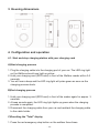
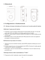
3. Housing dimensions
4. Conguration and operation
4.1. Start and stop charging station with your charging card
A) Start charging process
1. Plug the charging cable into the charging port of your car. The LED ring light
on the Wallbox should now light up yellow.
2. Hold your charging card (RFID card) in front of the Wallbox reader within 3-5
seconds.
3. You will hear a beep and the LED ring light will pulse green as soon as the
charging process starts.
B) End charging process
1. Hold your charging card (RFID card) in front of the reader again for approx. 3
seconds.
2. A beep sounds again, the LED ring light lights up green when the charging
process is completed.
3. Disconnect the charging cable from your car and reattach the charging cable
to the cable holder.
C) Resetting the "Total" display
1. Press the red emergency stop button on the wallbox three times.
- 14 -

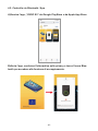
4.2. Control via Bluetooth / App
A) Download the „YOOZI EV“ app from the Google PlayStore or the Apple
App Store.
B) Launch the app, conrm the privacy policy and tap the Bluetooth icon
to access the pairing function.
- 15 -

C) Connect via Bluetooth
1. Add a new device.
2. Enter the number of the Wallbox, which is shown on the Wallbox display, into
the app or scan the QR code.
3. Enter the password 123456 (can be changed later).
4. Then connect the Wallbox to the app.
D) Pairing
If a connection is established, you will see „connectable“ next to the Wallbox
number.
1. Tap on the device number and wait about 10 seconds, the pairing is now
established, the next steps can take place.
2. If the pairing does not work, please switch off Bluetooth of your smartphone,
wait 3 seconds and activate Bluetooth again.
3. Then start the pairing process again.
- 16 -

E) Start charging process
1. Connect the charging gun to your electric car.
2. Start the charging process.
- 17 -

F) Change the key (password) of the Wallbox
3. Tap on the password/key modication.
4. Enter the new password.
1. Conrm the change.
G) Scheduling the charging process
1. Activate time-controlled charging.
2. Set the desired time.
3. Start the charging process.
4. Conrm that charging is to take place at a specic time.
- 18 -

5. LED status
Color Status Meaning Action
off The Wallbox is ready for
use.
Please connect the
charging cable.
yellow
The charging cable is
connected.
Please hold the RFID
card up to the card
reader.
green (pulsed) The charging process is
active.
Please wait or cancel
the charging process.
green The charging process is
completed.
Please remove the
charging cable.
red An error has occurred. Please check chapter
6. Error codes.
6. Error codes and suggested solutions
Error Possible reason Solutions
Overvolta-
ge
AC input voltage too
high
Input voltage must be checked.
If the voltage is above 264V (AC), wait
until the power grid is back in the normal
voltage range. Switch the Wallbox off and
on again.
If the error persists, please contact the
dealer.
Undervol-
tage
AC input voltage too
low
The input voltage must be checked.
If the voltage is below 140 (AC), wait until
the power grid is back within the normal
voltage range. Switch the Wallbox off and
on again.
If the fault cannot be rectied, please
contact the dealer or a specialist compa-
ny.
- 19 -

Overcurrent AC input current too
high
Immediately switch off the overcurrent
circuit breaker in the distribution cabinet.
It is necessary to check if there is a low
resistance connection between two AC
output wires.
After this error has been corrected, the
Wallbox can be switched on again. If the
error persists, please contact the dealer.
EPO error Emergency stop
button is pressed
Reset the emergency stop button on the
right side of the Wallbox.
Leading
error
Leakage current
(ground leakage)
too high
Immediately switch off the overcurrent
circuit breaker in the distribution cabinet.
Check whether the AC output devices are
interrupted or there is a low resistance
connection to earth.
After this fault has been corrected, the
Wallbox can be switched on again. If the
error persists, please contact the dealer.
NE fault Grounding incorrect
or connection faulty Immediately switch off the overcurrent
circuit breaker in the distribution cabinet.
It must be checked whether the AC wiring
is working properly.
After this error has been corrected, the
Wallbox can be switched on again. If the
error persists, please contact the dealer.
- 20 -
La pagina si sta caricando...
La pagina si sta caricando...
La pagina si sta caricando...
La pagina si sta caricando...
La pagina si sta caricando...
La pagina si sta caricando...
La pagina si sta caricando...
La pagina si sta caricando...
La pagina si sta caricando...
La pagina si sta caricando...
La pagina si sta caricando...
La pagina si sta caricando...
La pagina si sta caricando...
La pagina si sta caricando...
La pagina si sta caricando...
La pagina si sta caricando...
La pagina si sta caricando...
La pagina si sta caricando...
La pagina si sta caricando...
La pagina si sta caricando...
La pagina si sta caricando...
La pagina si sta caricando...
La pagina si sta caricando...
La pagina si sta caricando...
La pagina si sta caricando...
La pagina si sta caricando...
La pagina si sta caricando...
La pagina si sta caricando...
La pagina si sta caricando...
La pagina si sta caricando...
La pagina si sta caricando...
La pagina si sta caricando...
La pagina si sta caricando...
La pagina si sta caricando...
La pagina si sta caricando...
La pagina si sta caricando...
La pagina si sta caricando...
La pagina si sta caricando...
La pagina si sta caricando...
La pagina si sta caricando...
La pagina si sta caricando...
La pagina si sta caricando...
La pagina si sta caricando...
La pagina si sta caricando...
La pagina si sta caricando...
La pagina si sta caricando...
La pagina si sta caricando...
La pagina si sta caricando...
La pagina si sta caricando...
La pagina si sta caricando...
La pagina si sta caricando...
La pagina si sta caricando...
La pagina si sta caricando...
La pagina si sta caricando...
La pagina si sta caricando...
La pagina si sta caricando...
La pagina si sta caricando...
La pagina si sta caricando...
La pagina si sta caricando...
La pagina si sta caricando...
La pagina si sta caricando...
La pagina si sta caricando...
La pagina si sta caricando...
La pagina si sta caricando...
La pagina si sta caricando...
La pagina si sta caricando...
La pagina si sta caricando...
La pagina si sta caricando...
La pagina si sta caricando...
La pagina si sta caricando...
La pagina si sta caricando...
La pagina si sta caricando...
La pagina si sta caricando...
La pagina si sta caricando...
La pagina si sta caricando...
La pagina si sta caricando...
La pagina si sta caricando...
La pagina si sta caricando...
La pagina si sta caricando...
La pagina si sta caricando...
La pagina si sta caricando...
La pagina si sta caricando...
La pagina si sta caricando...
La pagina si sta caricando...
La pagina si sta caricando...
La pagina si sta caricando...
La pagina si sta caricando...
La pagina si sta caricando...
La pagina si sta caricando...
La pagina si sta caricando...
La pagina si sta caricando...
La pagina si sta caricando...
La pagina si sta caricando...
La pagina si sta caricando...
La pagina si sta caricando...
La pagina si sta caricando...
La pagina si sta caricando...
La pagina si sta caricando...
La pagina si sta caricando...
La pagina si sta caricando...
La pagina si sta caricando...
La pagina si sta caricando...
La pagina si sta caricando...
La pagina si sta caricando...
La pagina si sta caricando...
La pagina si sta caricando...
La pagina si sta caricando...
La pagina si sta caricando...
La pagina si sta caricando...
La pagina si sta caricando...
La pagina si sta caricando...
La pagina si sta caricando...
La pagina si sta caricando...
La pagina si sta caricando...
La pagina si sta caricando...
La pagina si sta caricando...
La pagina si sta caricando...
La pagina si sta caricando...
La pagina si sta caricando...
La pagina si sta caricando...
La pagina si sta caricando...
La pagina si sta caricando...
La pagina si sta caricando...
La pagina si sta caricando...
La pagina si sta caricando...
La pagina si sta caricando...
La pagina si sta caricando...
La pagina si sta caricando...
La pagina si sta caricando...
La pagina si sta caricando...
La pagina si sta caricando...
La pagina si sta caricando...
La pagina si sta caricando...
La pagina si sta caricando...
La pagina si sta caricando...
La pagina si sta caricando...
La pagina si sta caricando...
La pagina si sta caricando...
La pagina si sta caricando...
La pagina si sta caricando...
La pagina si sta caricando...
La pagina si sta caricando...
La pagina si sta caricando...
La pagina si sta caricando...
La pagina si sta caricando...
La pagina si sta caricando...
La pagina si sta caricando...
La pagina si sta caricando...
La pagina si sta caricando...
La pagina si sta caricando...
La pagina si sta caricando...
La pagina si sta caricando...
-
 1
1
-
 2
2
-
 3
3
-
 4
4
-
 5
5
-
 6
6
-
 7
7
-
 8
8
-
 9
9
-
 10
10
-
 11
11
-
 12
12
-
 13
13
-
 14
14
-
 15
15
-
 16
16
-
 17
17
-
 18
18
-
 19
19
-
 20
20
-
 21
21
-
 22
22
-
 23
23
-
 24
24
-
 25
25
-
 26
26
-
 27
27
-
 28
28
-
 29
29
-
 30
30
-
 31
31
-
 32
32
-
 33
33
-
 34
34
-
 35
35
-
 36
36
-
 37
37
-
 38
38
-
 39
39
-
 40
40
-
 41
41
-
 42
42
-
 43
43
-
 44
44
-
 45
45
-
 46
46
-
 47
47
-
 48
48
-
 49
49
-
 50
50
-
 51
51
-
 52
52
-
 53
53
-
 54
54
-
 55
55
-
 56
56
-
 57
57
-
 58
58
-
 59
59
-
 60
60
-
 61
61
-
 62
62
-
 63
63
-
 64
64
-
 65
65
-
 66
66
-
 67
67
-
 68
68
-
 69
69
-
 70
70
-
 71
71
-
 72
72
-
 73
73
-
 74
74
-
 75
75
-
 76
76
-
 77
77
-
 78
78
-
 79
79
-
 80
80
-
 81
81
-
 82
82
-
 83
83
-
 84
84
-
 85
85
-
 86
86
-
 87
87
-
 88
88
-
 89
89
-
 90
90
-
 91
91
-
 92
92
-
 93
93
-
 94
94
-
 95
95
-
 96
96
-
 97
97
-
 98
98
-
 99
99
-
 100
100
-
 101
101
-
 102
102
-
 103
103
-
 104
104
-
 105
105
-
 106
106
-
 107
107
-
 108
108
-
 109
109
-
 110
110
-
 111
111
-
 112
112
-
 113
113
-
 114
114
-
 115
115
-
 116
116
-
 117
117
-
 118
118
-
 119
119
-
 120
120
-
 121
121
-
 122
122
-
 123
123
-
 124
124
-
 125
125
-
 126
126
-
 127
127
-
 128
128
-
 129
129
-
 130
130
-
 131
131
-
 132
132
-
 133
133
-
 134
134
-
 135
135
-
 136
136
-
 137
137
-
 138
138
-
 139
139
-
 140
140
-
 141
141
-
 142
142
-
 143
143
-
 144
144
-
 145
145
-
 146
146
-
 147
147
-
 148
148
-
 149
149
-
 150
150
-
 151
151
-
 152
152
-
 153
153
-
 154
154
-
 155
155
-
 156
156
-
 157
157
-
 158
158
-
 159
159
-
 160
160
-
 161
161
-
 162
162
-
 163
163
-
 164
164
-
 165
165
-
 166
166
-
 167
167
-
 168
168
-
 169
169
-
 170
170
-
 171
171
-
 172
172


in altre lingue
- français: PATONA WB1-11 Manuel utilisateur
- español: PATONA WB1-11 Manual de usuario
- Deutsch: PATONA WB1-11 Benutzerhandbuch
- polski: PATONA WB1-11 Instrukcja obsługi
Altri documenti
-
eSolutions eProWallbox Move Istruzioni per l'uso
-
Bosch PC7000i 11-5 Manuale utente
-
Wallbox Commander 2 Fast and Powerful Charger Guida d'installazione
-
Wallbox Commander 2 Guida d'installazione
-
Wallbox PLP2-0-2-2-F-002 Guida d'installazione
-
 ensto Chago Wallbox Guida d'installazione
-
Wall Box Chargers SL WBPL-0-2-4-0-002-A Guida d'installazione
-
-
Western WE-BOX Manuale del proprietario
-
