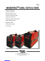
INVERTEC V270 Manuale utente
- Categoria
- Sistema di saldatura
- Tipo
- Manuale utente
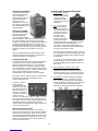
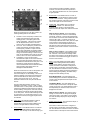
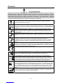
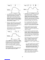
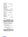
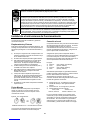
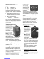
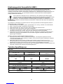
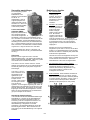
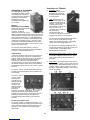
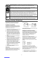
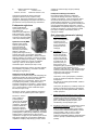
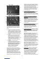
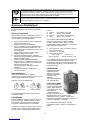
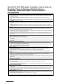
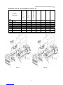
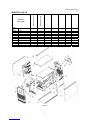
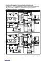
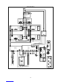
Di seguito troverete brevi informazioni per INVERTEC V205, INVERTEC V270, INVERTEC V405. Questi dispositivi sono progettati per la saldatura ad arco con opzioni di saldatura stick (MMA) e TIG (GTAW). I modelli V205-T, V270-T e V405-T hanno tre modalità di saldatura stick (SMAW), Lift TIG (GTAW) e HF TIG (GTAW). Le saldatrici hanno una funzione di avvio a caldo per un innesco rapido e affidabile dell'arco, e una funzione di forza dell’arco per eliminare le interruzioni durante la saldatura stick. La funzione anti-incollatura riduce la corrente quando l'elettrodo si attacca al pezzo in lavorazione
Di seguito troverete brevi informazioni per INVERTEC V205, INVERTEC V270, INVERTEC V405. Questi dispositivi sono progettati per la saldatura ad arco con opzioni di saldatura stick (MMA) e TIG (GTAW). I modelli V205-T, V270-T e V405-T hanno tre modalità di saldatura stick (SMAW), Lift TIG (GTAW) e HF TIG (GTAW). Le saldatrici hanno una funzione di avvio a caldo per un innesco rapido e affidabile dell'arco, e una funzione di forza dell’arco per eliminare le interruzioni durante la saldatura stick. La funzione anti-incollatura riduce la corrente quando l'elettrodo si attacca al pezzo in lavorazione


-
 1
1
-
 2
2
-
 3
3
-
 4
4
-
 5
5
-
 6
6
-
 7
7
-
 8
8
-
 9
9
-
 10
10
-
 11
11
-
 12
12
-
 13
13
-
 14
14
-
 15
15
-
 16
16
-
 17
17
-
 18
18
-
 19
19
-
 20
20
-
 21
21
-
 22
22
-
 23
23
-
 24
24
-
 25
25
-
 26
26
-
 27
27
-
 28
28
-
 29
29
-
 30
30
-
 31
31
-
 32
32
-
 33
33
-
 34
34
-
 35
35
-
 36
36
-
 37
37
-
 38
38
-
 39
39
-
 40
40
-
 41
41
-
 42
42
-
 43
43
-
 44
44
-
 45
45
-
 46
46
-
 47
47
-
 48
48
-
 49
49
-
 50
50
-
 51
51
-
 52
52
-
 53
53
-
 54
54
-
 55
55
-
 56
56
-
 57
57
-
 58
58
-
 59
59
-
 60
60
-
 61
61
-
 62
62
-
 63
63
-
 64
64
-
 65
65
-
 66
66
-
 67
67
-
 68
68
-
 69
69
-
 70
70
-
 71
71
-
 72
72
-
 73
73
-
 74
74
-
 75
75
-
 76
76
-
 77
77
-
 78
78
-
 79
79
-
 80
80
-
 81
81
-
 82
82
-
 83
83
-
 84
84
-
 85
85
-
 86
86
-
 87
87
-
 88
88
-
 89
89
-
 90
90
-
 91
91
-
 92
92
-
 93
93
-
 94
94
-
 95
95
-
 96
96
-
 97
97
-
 98
98
-
 99
99
-
 100
100
-
 101
101
-
 102
102
-
 103
103
-
 104
104
-
 105
105
-
 106
106


INVERTEC V270 Manuale utente
- Categoria
- Sistema di saldatura
- Tipo
- Manuale utente
Di seguito troverete brevi informazioni per INVERTEC V205, INVERTEC V270, INVERTEC V405. Questi dispositivi sono progettati per la saldatura ad arco con opzioni di saldatura stick (MMA) e TIG (GTAW). I modelli V205-T, V270-T e V405-T hanno tre modalità di saldatura stick (SMAW), Lift TIG (GTAW) e HF TIG (GTAW). Le saldatrici hanno una funzione di avvio a caldo per un innesco rapido e affidabile dell'arco, e una funzione di forza dell’arco per eliminare le interruzioni durante la saldatura stick. La funzione anti-incollatura riduce la corrente quando l'elettrodo si attacca al pezzo in lavorazione
in altre lingue
- français: INVERTEC V270 Manuel utilisateur
- español: INVERTEC V270 Manual de usuario
- Deutsch: INVERTEC V270 Benutzerhandbuch
- Nederlands: INVERTEC V270 Handleiding
- dansk: INVERTEC V270 Brugermanual
- polski: INVERTEC V270 Instrukcja obsługi
- svenska: INVERTEC V270 Användarmanual
Documenti correlati
Altri documenti
-
Lincoln Electric Invertec 170S Manuale utente
-
-
-
-
-
-
Miller COOLPACK 1 Manuale del proprietario
-
GYS NEOPULSE 320 C Manuale del proprietario
-
-
GYS GYSARC 300 A TRI Manuale del proprietario