
MX150 Universal Roung Plaorm
Hardware Guide
Published
2022-12-05

Juniper Networks, Inc.
1133 Innovaon Way
Sunnyvale, California 94089
USA
408-745-2000
www.juniper.net
Juniper Networks, the Juniper Networks logo, Juniper, and Junos are registered trademarks of Juniper Networks, Inc.
in the United States and other countries. All other trademarks, service marks, registered marks, or registered service
marks are the property of their respecve owners.
Juniper Networks assumes no responsibility for any inaccuracies in this document. Juniper Networks reserves the right
to change, modify, transfer, or otherwise revise this publicaon without noce.
MX150 Universal Roung Plaorm Hardware Guide
Copyright © 2022 Juniper Networks, Inc. All rights reserved.
The informaon in this document is current as of the date on the tle page.
YEAR 2000 NOTICE
Juniper Networks hardware and soware products are Year 2000 compliant. Junos OS has no known me-related
limitaons through the year 2038. However, the NTP applicaon is known to have some diculty in the year 2036.
END USER LICENSE AGREEMENT
The Juniper Networks product that is the subject of this technical documentaon consists of (or is intended for use
with) Juniper Networks soware. Use of such soware is subject to the terms and condions of the End User License
Agreement ("EULA") posted at hps://support.juniper.net/support/eula/. By downloading, installing or using such
soware, you agree to the terms and condions of that EULA.
ii

Table of Contents
About This Guide | vii
1
Overview
MX150 Router Overview | 2
MX150 Chassis | 4
Chassis Physical Specicaons for an MX150 | 4
Front Panel of an MX150 | 5
Rear Panel of an MX150 | 6
Chassis Status LEDs on MX150 | 7
Network Port and Uplink Port LEDs on MX150 | 8
Management Port LEDs on MX150 | 11
MX150 Cooling System | 12
MX150 Power System | 13
Power Supply in MX150 | 13
AC Power Supply Specicaons for an MX150 | 13
AC Power Cord Specicaons for an MX150 | 14
2
Site Planning, Preparaon, and Specicaons
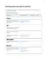
Site Preparaon Checklist for MX150 | 18
MX150 Site Guidelines and Requirements | 20
General Site Guidelines | 21
Site Electrical Wiring Guidelines | 21
Environmental Requirements and Specicaons for an MX150 | 22
Clearance Requirements for Airow and Hardware Maintenance for an MX150 | 24
Requirements for Mounng an MX150 on a Desktop or Other Level Surface | 25
Cabinet Requirements for an MX150 | 25
iii

Rack Requirements for an MX150 | 26
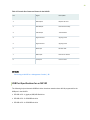
MX150 Management and Console Port Specicaons and Pinouts | 28
Mini-USB Type-B Console Port Specicaons for an MX150 | 28
Console Port Connector Pinouts for MX150 | 29
USB Port Specicaons for an MX150 | 30
Network Port Connector Pinout Informaon for an MX150 | 31
RJ-45 to DB-9 Serial Port Adapter Pinout Informaon for an MX150 | 32
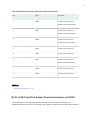
MX150 Network Cable and Transceiver Planning | 33
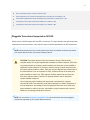
Pluggable Transceivers Supported on MX150 | 34
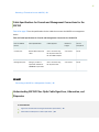
SFP+ Direct Aach Copper Cables for MX150 | 35
Cable Specicaons for Console and Management Connecons for the MX150 | 37
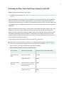
Understanding MX150 Fiber-Opc Cable Signal Loss, Aenuaon, and Dispersion | 37
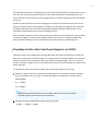
Calculang the Fiber-Opc Cable Power Budget for an MX150 | 39
Calculang the Fiber-Opc Cable Power Margin for an MX150 | 40
3
Inial Installaon and Conguraon
MX150 Installaon Overview | 43
Unpacking and Mounng the MX150 | 43
Unpacking an MX150 | 44
Parts Inventory (Packing List) for an MX150 | 44
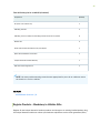
Register Products—Mandatory to Validate SLAs | 45
Mounng an MX150 | 46
Mounng an MX150 on a Desk or Other Level Surface | 47
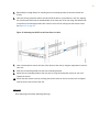
Mounng an MX150 on Two Posts in a Rack | 48
Mounng an MX150 on Four Posts in a Rack or Cabinet | 50
Connecng the MX150 to Power | 53
Connecng Earth Ground to an MX150 | 53
iv

Connecng AC Power to an MX150 | 55
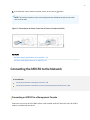
Connecng the MX150 to the Network | 56
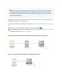
Connecng an MX150 to a Management Console | 56
Connecng an MX150 to a Management Console Using Mini-USB Type-B Console Port | 58
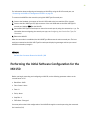
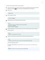
Performing the Inial Soware Conguraon for the MX150 | 59
4
Maintaining Components
Maintaining MX150 Transceivers and Fiber-Opc Cables | 63
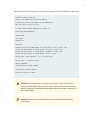
Removing a Transceiver from an MX150 | 63
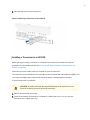
Installing a Transceiver in an MX150 | 65
Maintaining Fiber-Opc Cables in an MX150 | 67
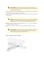
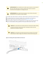
Connecng a Fiber-Opc Cable to an MX150 | 67
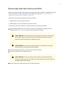
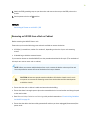
Disconnecng a Fiber-Opc Cable from an MX150 | 69
Removing the MX150 | 70
Powering O an MX150 | 70
Removing an MX150 from a Rack or Cabinet | 72
5
Troubleshoong Hardware
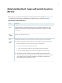
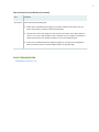
Understanding Alarm Types and Severity Levels on MX150 | 75
6
Contacng Customer Support and Returning the Chassis or Components
Contacng Customer Support and Returning the Chassis or Components | 78
Contacng Customer Support to Obtain a Return Materials Authorizaon for an MX150 | 78
Locang the Serial Number on an MX150 | 79
Lisng the Device and Components Details with the CLI | 79
Locang the Chassis Serial Number ID Label on an MX150 | 80
Packing a MX150 Router or Component for Shipping | 81
Packing an MX150 for Shipping | 81
Packing MX150 Components for Shipping | 82
Returning a MX150 Router or Component for Repair or Replacement | 82
v

7
Safety and Compliance Informaon
General Safety Guidelines and Warnings | 86
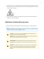
Denions of Safety Warning Levels | 87
Qualied Personnel Warning | 89
Warning Statement for Norway and Sweden | 89
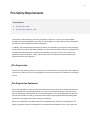
Fire Safety Requirements | 90
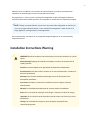
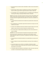
Installaon Instrucons Warning | 91
Chassis Liing Guidelines for MX150 | 92
Restricted Access Warning | 92
Ramp Warning | 93
Rack-Mounng and Cabinet-Mounng Warnings | 94
Laser and LED Safety Guidelines and Warnings for the MX150 | 98
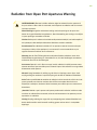
Radiaon from Open Port Apertures Warning | 104
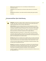
Maintenance and Operaonal Safety Guidelines and Warnings | 105
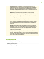
General Electrical Safety Guidelines and Warnings | 110
Acon to Take Aer an Electrical Accident | 112
Prevenon of Electrostac Discharge Damage | 112
AC Power Electrical Safety Guidelines | 114
AC Power Disconnecon Warning | 115
TN Power Warning | 116
Agency Approvals for MX150 | 117
Compliance Statements for EMC Requirements for MX150 | 119
vi


MX150 Router Overview
IN THIS SECTION
Benets of MX150 Router | 2
MX150 Hardware | 3
System Soware | 4
The MX150 Universal Roung Plaorm is a compact, high-performance edge router that is ideally suited
for lower bandwidth service provider applicaons and distributed service architectures, and for
enterprise WAN use-cases. The MX150 supports advanced technologies like telemetry that simplify
your operaons environment, and maximize network upme.
The MX150 is 1 rack unit (U) tall. The MX150 can be mounted on a desk or any other level surface, on
two posts in a Rack, and on four pots in a rack or Cabinet. The MX150 conserves space and contains
costs associated with power and cooling.
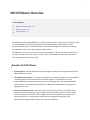
Benets of MX150 Router
•System Capacity—MX150 provides 20 Gbps of throughput and supports 1-Gigabit Ethernet and 10-
Gigabit Ethernet interfaces.
•The Programmable Chipset—The chipset implemented in the MX Series routers has a programmable
forwarding data structure that allows fast microcode changes in the hardware itself, and a
programmable lookup engine that allows inline service processing. the chip’s programmable QoS
engine supports coarse and ne-grained queuing to address the requirements of core, edge, and
aggregaon use cases.
•Always-on infrastructure base—MX Series routers ensure network and service availability with a
broad set of mullayered physical, logical, and protocol-level resiliency aspects. Junos OS Virtual
Chassis technology on MX Series routers supports chassis-level redundancy and enables you to
manage two routers as a single element. Mulchassis link aggregaon group (MC-LAG)
implementaon supports stateful chassis, card, and port redundancy.
2

•Applicaon-Aware Networking—On MX Series routers you can use deep packet inspecon to detect
applicaons, and by using the user-dened policies, you can determine trac treatment for each
applicaon. This feature enables highly customized and dierenated services at scale.
•Junos Connuity and Unied In-Service Soware Upgrade (Unied ISSU)—With the Junos
connuity plug-in package, you can perform a smooth upgrade when new hardware is installed in
your MX Series router.
Unied in-service soware upgrade (unied ISSU) enables soware upgrades and changes without
disrupng network trac.
•Junos Telemetry Interface—Using the Junos telemetry interface data, you can stream component-
level data to monitor, analyze, and enhance the performance of the network. Analycs derived from
this streaming telemetry can idenfy current and trending congeson, resource ulizaon, trac
volume, and buer occupancy.
•Integrated Hardware-Based Timing— You do not need to use external clocks because MX Series
routers support highly scalable and reliable hardware-based ming, including Synchronous Ethernet
for frequency, and the Precision Time Protocol (PTP) for frequency and phase synchronizaon.
Synchronous Ethernet and PTP can be combined in a hybrid mode to achieve a high level of
frequency (10 ppb) and phase (<1.5 uS) accuracy.
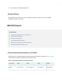
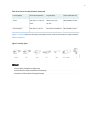
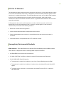
MX150 Hardware
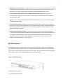
The MX150 provide carrier-grade level of a rich set of Layer 2 and Layer 3 features. The MX150 has
eight 1-Gigabit Ethernet network ports, two 1-Gigabit Ethernet RJ-45 ports that can be used as either
access ports or as uplink ports, two SFP ports, two SFP+ ports, and one management port. The MX150
has a 1 U form factor and is shipped with built-in fans and power supply.
Figure 1: MX150 Port Panel
The MX150 can be used as:
• An integrated branch router.
3

• A secure router for distributed enterprises.
System Soware
The MX150 use the Junos OS CLI. You can manage the device by using the Junos CLI, accessible
through the console on the device.
MX150 Chassis
IN THIS SECTION
Chassis Physical Specicaons for an MX150 | 4
Front Panel of an MX150 | 5
Rear Panel of an MX150 | 6
Chassis Status LEDs on MX150 | 7
Network Port and Uplink Port LEDs on MX150 | 8
Management Port LEDs on MX150 | 11
Chassis Physical Specicaons for an MX150
MX150 chassis is a rigid sheet-metal structure that houses the hardware components. Table 1 on page
4 summarizes the physical specicaons of the MX150 chassis.
Table 1: Physical Specicaons for the MX150 Chassis
Product SKU Height Width Depth Weight
MX150 1.72 in. (4.3 cm) 17.36 in. (44.1 cm) 12 in. (30.5 cm) 9.4 lb (4.3 kg)
4

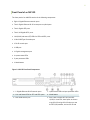
Front Panel of an MX150
The front panel of an MX150 consists of the following components:
• Eight 1-Gigabit Ethernet network ports
• Two 1-Gigabit Ethernet RJ-45 access ports or uplink ports
• Two 1-Gigabit SFP ports
• Two 1/10-Gigabit SFP+ ports
• Link (LINK) and status (ST) LEDs for SFP and SFP+ ports
• 1 Mini-USB Type-B console port
• 1 RJ-45 console port
• 1 USB port
• 1-Gigabit management port
• 4 system status LEDs
• 3 port parameter LEDs
• 1 Mode buon
Figure 2: MX150 Front Panel Components
1—1-Gigabit Ethernet RJ-45 network ports 7—system status LEDs and port parameter LEDs
2—Link and Status LEDs for SFP and SFP+ ports 8—Mode buon
3—Mini-USB console port 9—Port 0 and 1 support SFP (1G) and SFP
+(10G). In Junos CLI, these ports are shown
as ge-0/0/12 and ge-0/0/13 when you use
the SFP (1G) modules, and xe-0/0/12 and
5

xe-0/0/13 when you use the SFP+ (10G)
modules.
4—Console (CON) port 10—Port: 10 and 11 support SFP only;
5—USB port 11—1-Gigabit Ethernet RJ-45 network or uplink
ports
6—1-Gigabit management (mgmt) port
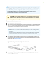
CAUTION: Do not use the Reset buon to restart the power sequence unless under the
direcon of Juniper Networks Technical Assistance Center (JTAC).
SEE ALSO
Prevenon of Electrostac Discharge Damage
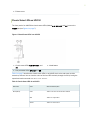
Rear Panel of an MX150
The rear panel of the MX150 consists of the following components (see Figure 3 on page 6):
• Ground area
•Electrostac discharge (ESD) point
• Exhaust vents
• Power switch
• AC power cord inlet
Figure 3: MX150 Rear Panel
1—Ground area 4—Power switch
2—Electrostac discharge (ESD) point 5—AC power cord inlet
6

3—Exhaust vents
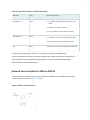
Chassis Status LEDs on MX150
The front panel of an MX150 has chassis status LEDs (labeled ALM, SYS, MST and PH), next to the
MGMT port (see Figure 4 on page 7).
Figure 4: Chassis Status LEDs in an MX150
1—Chassis status LEDs (ALM, SYS, MST, and
PH)
3—Mode buon
2—Port parameter LEDs (SPD, DX, and EN)
Table 2 on page 7 describes the chassis status LEDs on an MX150, their colors and states, and the
status they indicate. You can view the colors of the four LEDs remotely through the CLI by issuing the
operaonal mode command show chassis craft-interface.
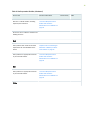
Table 2: Chassis Status LEDs in an MX150
LED Label Color State and Descripon
ALM (Alarm) Unlit There is no alarm or the device is halted.
Red There is a major alarm.
Amber There is a minor alarm.
7

Table 2: Chassis Status LEDs in an MX150
(Connued)
LED Label Color State and Descripon
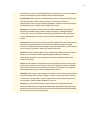
SYS (System) Green •On steadily—Junos OS has been loaded on the
device.
•Blinking—The device is boong.
•O—The device is powered o or is halted.
MST (Primary) Green •On steadily—The device is funconing normally.
•O—The device is powered o or is halted.
PH Unlit This LED is not used. So, the status of this LED is o.
A major alarm (red) indicates a crical error condion that requires immediate acon.
A minor alarm (amber) indicates a noncrical condion that requires monitoring or maintenance. A
minor alarm le unchecked might cause interrupon in service or performance degradaon.
All three LEDs can be lit simultaneously.
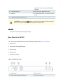
Network Port and Uplink Port LEDs on MX150
Each network port and uplink port on the front panel of an MX150 has two LEDs that indicate link
acvity and port status (see Figure 5 on page 8).
Figure 5: LEDs on the Network Port
8

Table 3 on page 9 describes the link acvity of the LED.
Table 3: Link acvity LED on the Network Ports and Uplink Ports in MX150
LED Color State and Descripon
Link acvity Green •Blinking—The port and the link are acve, and there is link
acvity.
•On steadily—The port and the link are acve, but there is no link
acvity.
•O—The port is not acve.
Figure 6 on page 9 shows the LEDs that indicate the status of one of the three port parameters—
speed, duplex mode, and administrave status. Use the Mode buon on the far right side of the front
panel to display the status LED for the dierent port parameters. You can tell which port parameter
(speed, duplex mode, or administrave status) is indicated by the ST LED by looking at which port
parameter LED (SPD, DX, or EN) is lit.
Figure 6: Port Parameter LEDs of an MX150
1—Chassis status LEDs (ALM, SYS, MST, and
PH)
3—Mode buon
2—Port parameter LEDs (SPD, DX, and EN)
Table 4 on page 10 describes the port parameters LED.
9

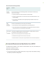
Table 4: Port Parameter LED on the Network Ports and Uplink Ports in MX150
Port Parameter LED State and Descripon
SPD (speed) Indicates the speed. The speed indicators for network ports and uplink
ports are:
•One blink per second—10 Mbps
•Two blinks per second—100 Mbps
•Three blinks per second—1000 Mbps
DX (duplex mode) Indicates the duplex mode. The status indicators are:
•On steadily—Port is set to full-duplex mode.
•O—Port is set to half-duplex mode.
EN (administrave status) Indicates the administrave status. The status indicators are:
•On steadily—Port is administravely enabled.
•O—Port is administravely disabled.
You can tell which port parameter is indicated by the Status LED on network ports by issuing the
operaonal mode command show chassis craft-interface.
10

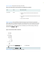
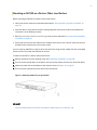
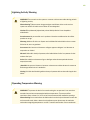
Management Port LEDs on MX150
The management port on the front panel of an MX150 has two LEDs that indicate link acvity and port
status (see Figure 7 on page 11).
Figure 7: LEDs on the Management Port of an MX150
1—Link acvity 2—Status
Table 5 on page 11 describes the Link acvity LED.
Table 5: Link acvity LED on the Management Port of an MX150
LED Color State and Descripon
Link acvity Green •Blinking—The port and the link are acve, and there
is link acvity.
•On steadily—The port and the link are acve, but
there is no link acvity.
•O—The port is not acve.
Table 6 on page 12 describes the status LED.
11

Table 6: Status LED on the Management Port of an MX150
LED Color State and Descripon
Status Green Indicates the speed. The speed indicators are:
•One blink per second—10 Mbps
•Two blinks per second—100 Mbps
•Three blinks per second—1000 Mbps
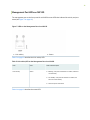
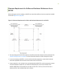
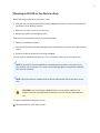
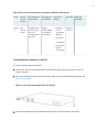
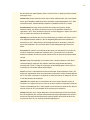
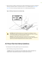
MX150 Cooling System
The MX150 has front-to-back airow. The air intake to cool the chassis is located at the front of the
chassis. Air is pulled into the chassis and pushed toward the fans, which are built-in. Hot air exhausts
from the rear of the chassis. See Figure 8 on page 12.
Figure 8: Front-to-Back Airow Through the MX150 Chassis
12

RELATED DOCUMENTATION
Prevenon of Electrostac Discharge Damage
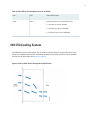
MX150 Power System
IN THIS SECTION
Power Supply in MX150 | 13
AC Power Supply Specicaons for an MX150 | 13
AC Power Cord Specicaons for an MX150 | 14
Power Supply in MX150
The MX150 routers use a xed, internal AC power supply. The power supply distributes dierent output
voltages to the device components according to their voltage requirements. The power supply is xed in
the chassis and is not eld-replaceable.
The power supply has a single AC appliance inlet that requires a dedicated AC power feed. The AC
power cord inlet is on the rear panel of the device.
SEE ALSO
Connecng AC Power to an MX150 | 55
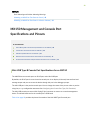
AC Power Supply Specicaons for an MX150
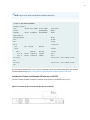
Table 7 on page 14 describes the AC power specicaons for an MX150.
13
La pagina si sta caricando...
La pagina si sta caricando...
La pagina si sta caricando...
La pagina si sta caricando...
La pagina si sta caricando...
La pagina si sta caricando...
La pagina si sta caricando...
La pagina si sta caricando...
La pagina si sta caricando...
La pagina si sta caricando...
La pagina si sta caricando...
La pagina si sta caricando...
La pagina si sta caricando...
La pagina si sta caricando...
La pagina si sta caricando...
La pagina si sta caricando...
La pagina si sta caricando...
La pagina si sta caricando...
La pagina si sta caricando...
La pagina si sta caricando...
La pagina si sta caricando...
La pagina si sta caricando...
La pagina si sta caricando...
La pagina si sta caricando...
La pagina si sta caricando...
La pagina si sta caricando...
La pagina si sta caricando...
La pagina si sta caricando...
La pagina si sta caricando...
La pagina si sta caricando...
La pagina si sta caricando...
La pagina si sta caricando...
La pagina si sta caricando...
La pagina si sta caricando...
La pagina si sta caricando...
La pagina si sta caricando...
La pagina si sta caricando...
La pagina si sta caricando...
La pagina si sta caricando...
La pagina si sta caricando...
La pagina si sta caricando...
La pagina si sta caricando...
La pagina si sta caricando...
La pagina si sta caricando...
La pagina si sta caricando...
La pagina si sta caricando...
La pagina si sta caricando...
La pagina si sta caricando...
La pagina si sta caricando...
La pagina si sta caricando...
La pagina si sta caricando...
La pagina si sta caricando...
La pagina si sta caricando...
La pagina si sta caricando...
La pagina si sta caricando...
La pagina si sta caricando...
La pagina si sta caricando...
La pagina si sta caricando...
La pagina si sta caricando...
La pagina si sta caricando...
La pagina si sta caricando...
La pagina si sta caricando...
La pagina si sta caricando...
La pagina si sta caricando...
La pagina si sta caricando...
La pagina si sta caricando...
La pagina si sta caricando...
La pagina si sta caricando...
La pagina si sta caricando...
La pagina si sta caricando...
La pagina si sta caricando...
La pagina si sta caricando...
La pagina si sta caricando...
La pagina si sta caricando...
La pagina si sta caricando...
La pagina si sta caricando...
La pagina si sta caricando...
La pagina si sta caricando...
La pagina si sta caricando...
La pagina si sta caricando...
La pagina si sta caricando...
La pagina si sta caricando...
La pagina si sta caricando...
La pagina si sta caricando...
La pagina si sta caricando...
La pagina si sta caricando...
La pagina si sta caricando...
La pagina si sta caricando...
La pagina si sta caricando...
La pagina si sta caricando...
La pagina si sta caricando...
La pagina si sta caricando...
La pagina si sta caricando...
La pagina si sta caricando...
La pagina si sta caricando...
La pagina si sta caricando...
La pagina si sta caricando...
La pagina si sta caricando...
La pagina si sta caricando...
La pagina si sta caricando...
La pagina si sta caricando...
La pagina si sta caricando...
La pagina si sta caricando...
La pagina si sta caricando...
La pagina si sta caricando...
La pagina si sta caricando...
La pagina si sta caricando...
La pagina si sta caricando...
La pagina si sta caricando...
La pagina si sta caricando...
-
 1
1
-
 2
2
-
 3
3
-
 4
4
-
 5
5
-
 6
6
-
 7
7
-
 8
8
-
 9
9
-
 10
10
-
 11
11
-
 12
12
-
 13
13
-
 14
14
-
 15
15
-
 16
16
-
 17
17
-
 18
18
-
 19
19
-
 20
20
-
 21
21
-
 22
22
-
 23
23
-
 24
24
-
 25
25
-
 26
26
-
 27
27
-
 28
28
-
 29
29
-
 30
30
-
 31
31
-
 32
32
-
 33
33
-
 34
34
-
 35
35
-
 36
36
-
 37
37
-
 38
38
-
 39
39
-
 40
40
-
 41
41
-
 42
42
-
 43
43
-
 44
44
-
 45
45
-
 46
46
-
 47
47
-
 48
48
-
 49
49
-
 50
50
-
 51
51
-
 52
52
-
 53
53
-
 54
54
-
 55
55
-
 56
56
-
 57
57
-
 58
58
-
 59
59
-
 60
60
-
 61
61
-
 62
62
-
 63
63
-
 64
64
-
 65
65
-
 66
66
-
 67
67
-
 68
68
-
 69
69
-
 70
70
-
 71
71
-
 72
72
-
 73
73
-
 74
74
-
 75
75
-
 76
76
-
 77
77
-
 78
78
-
 79
79
-
 80
80
-
 81
81
-
 82
82
-
 83
83
-
 84
84
-
 85
85
-
 86
86
-
 87
87
-
 88
88
-
 89
89
-
 90
90
-
 91
91
-
 92
92
-
 93
93
-
 94
94
-
 95
95
-
 96
96
-
 97
97
-
 98
98
-
 99
99
-
 100
100
-
 101
101
-
 102
102
-
 103
103
-
 104
104
-
 105
105
-
 106
106
-
 107
107
-
 108
108
-
 109
109
-
 110
110
-
 111
111
-
 112
112
-
 113
113
-
 114
114
-
 115
115
-
 116
116
-
 117
117
-
 118
118
-
 119
119
-
 120
120
-
 121
121
-
 122
122
-
 123
123
-
 124
124
-
 125
125
-
 126
126
-
 127
127
-
 128
128
-
 129
129
-
 130
130


