
MIM-E03N
SAMSUNG CONTROL KIT
installation manual
imagine the possibilities
Thank you for purchasing this Samsung product.
EN
ES FR
IT
PT
DE
DB68-05388A-04
EHS MONO Kit-EU_IM_05388A-04_EN.indd 1 2016-06-23 오후 3:42:55

Contents
Safety precautions ....................................................................................................... 3
Product specications ................................................................................................... 4
Main components ....................................................................................................... 5
Installing the unit ........................................................................................................ 6
Wiring works ............................................................................................................ 9
Wiring schematics ...................................................................................................... 33
Self-test mode of wired remote controller ............................................................................... 34
Troubleshooting ........................................................................................................ 36
Error codes ............................................................................................................. 39
Mixing Valve ............................................................................................................ 41
Concrete curing function ................................................................................................ 44
Installation option setting ............................................................................................... 45
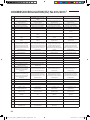
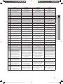
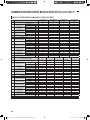
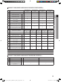
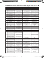
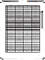
COMMISSION REGULATION (EU) No 813/2013
I
) ......................................................................... 47
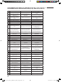
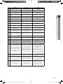
COMMISSION DELEGATED REGULATION (EU) No 811/2013
i
) ............................................................. 68
2
EHS MONO Kit-EU_IM_05388A-04_EN.indd 2 2016-06-23 오후 3:42:55

Safety precautions
Carefully follow the precautions listed as below because they are essential to guarantee the safety of SAMSUNG product.
WARNING
• Always disconnect a power supply of Air-Water Heat Pump before servicing it or accessing
components inside the unit.
• Verify that installation and testing operations shall be performed by qualied personnel.
• To prevent serious damage on the system and injuries to users, precautions and other
notices shall be observed.
Warning
Carefully read the contents of this manual before installing the control kit and store the manual in a safe place in order to
be able to use it as reference after installation.
For maximum safety, installers should always carefully read the following warnings.
Store the manual in a safe location and remember to hand it over to the new owner if the kit is sold or transferred.
The kit is compliant with the requirements of the Low Voltage Directive (72/23/EEC), the EMC Directive (89/336/EEC) and
the Directive on pressurized equipment (97/23/EEC).
The manufacturer shall not be responsible for damage originating from unauthorized changes or the improper
connection of electric and hydraulic lines. Failure to comply with these instructions or to comply with the requirements
set forth in the “Operating limits” table, included in the manual, shall immediately invalidate the warranty.
Do not use the units if you see some damages on the units and recognize something bad such as loud noisy, smell of
burning.
In order to prevent electric shocks, res or injuries, always stop the unit, disable the protection switch and contact
SAMSUNG’s technical support if the unit produces smoke, if the power cable is hot or damaged or if the unit is very noisy.
Always remember to inspect the unit, electric connections, and protections regularly. These operations shall be
performed by qualied personnel only.
The unit contains various electric parts, which should be kept out of the reach of children.
Do not attempt to repair, move, alter or reinstall the unit by unauthorized personnel, these operations may cause product
damage, electric shocks and res.
Do not place containers with liquids or other objects on the unit.
All the materials used for the manufacture and packaging of the air to water heat pump are recyclable.
The packing materials must be disposed of in accordance with local regulations.
Wear protective gloves to unpack, move, install, and service the unit to avoid your hands being injured by the edge of the
parts.
Do not touch the internal parts while running the units.
Inspect the product shipped and check if damaged during transport. If the product has some damages, DO NOT INSTALL
and immediately discuss about the damages with the carrier or retailer (if the installer or the authorized technician has
collected the material from the retailer.)
Our units shall be installed in compliance with the spaces described in the installation manual, to ensure accessibility
from both sides and allow repairs or maintenance operations to be carried out. If the units installed without complying
with procedures described in manual, additional expenses can be asked because special harnesses, ladders, scaolding
or any other elevation system for repair service will NOT be considered part of the warranty and will be charged to the
end customer.
When service works required, make sure to disconnect the power supply at least 1 minute to prevent electric shocks.
- Always check the voltage at the terminals of main PCB before trying to touch.
Use electric wires which manual designated. Connections between wires and terminals shall be assembled without any
tension. If the assembly works is not implemented well, it can lead to have product damages and res.
After wiring works, terminal block cover shall be xed rmly. Without cover, it can cause to have product damage and re.
Be sure not to perform power cable modication, midway wiring, and multiple wire connection.
- It may cause electric shock or re due to poor connection or insulation and current limit override.
- When midway wiring is required due to power line damage, refer to "How to connect your extended power cables" in
the installation manual.
3
ENGLISH
EHS MONO Kit-EU_IM_05388A-04_EN.indd 3 2016-06-23 오후 3:42:55

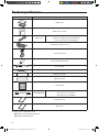
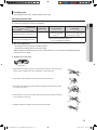
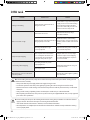
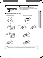
Product specications
Item Description
MIM-E03N
Wired remote controller
Temp. Sensor
Temp. Sensor for DHW Tank (15m, YEL) (1EA)
Temp. Sensor for Mixing Valve (15m, BLU) (1EA)
Temp. Sensor for Heater (15m, BLK) (1EA)
Smart Grid cable (Red, 2 m, 1EA)
Flow Switch (1EA, 2m)
Sensor holder (2EA, OD 7.8mm)
Sensor clip (2EA)
Cable tie (4EA)
Aluminum tape (2EA)
Rubber tape (2EA)
Insulartor (2EA)
LEAD CONNECTOR
Back-up heater conector (Red)
Back-up heater conector (Brown)
Back-up heater conector (White)
Installation manual
User manual
Temp. sensor = Temperature sensor
MIM-E03AN : 9/12/14/16 kW outdoor unit
MIM-E03BN : 5 kW outdoor unit
4
EHS MONO Kit-EU_IM_05388A-04_EN.indd 4 2016-06-23 오후 3:42:56

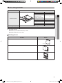
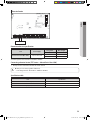
Main components
Model name MIM-E03N
Detail components
Parts Qty.
Main PBA 1
ELCB
- Rated current : 30A
- Leakage current : 30mA
1
Grounding screw 8
Rubber 4
Base plate 1
Top cover plate 1
Case screw 2
Weight (Net) 3.5kg
Packing size (W x H x D) 329mm x 439mm x 168mm
Flow Switch Set Point
MIM-E03AN (9/12/14/16 kW outdoor unit) : 16LPM
MIM-E03BN (5 kW outdoor unit) : 7LPM
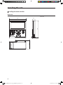
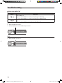
Mounting the unit
Procedure Remark
1. Remove 2 screw from the unit.
Screw
2. Open the top cover and install 4 screws on the wall.
3. Close the top cover and install 2 screw again into the unit.
5
ENGLISH
EHS MONO Kit-EU_IM_05388A-04_EN.indd 5 2016-06-23 오후 3:42:56

Installing the unit
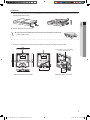
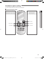
Installing the remote controller
Dimension
120
124
63.8
19.5
(Unit : mm)
6
EHS MONO Kit-EU_IM_05388A-04_EN.indd 6 2016-06-23 오후 3:42:56

Installation
1. Push the two hooks at the bottom of your Wired Remote Controller at the same time, and then pull up the front cover to
separate it from the rear cover.
Push the two hooks at the same time.
NOTE
• Insert a at head screwdriver into the square groove in the upper area of the hook
to disassemble it easily.
2. Arrange the communication cable so that they t in the housing along the edges of the rear cover.
If you need more space for the wiring
work, you can take it o.
15cm
<When the cable is not concealed> <When the cable is concealed>
10cm
7
ENGLISH
EHS MONO Kit-EU_IM_05388A-04_EN.indd 7 2016-06-23 오후 3:42:57

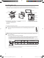
Installing the unit
3. Using more than two screws, rmly ax the rear cover of the remote controller to the wall, and then connect
communication cables(F3, F4), making sure these cables have reasonable length, to the terminal at the back of the cover.
10mm or more
10mm or more
50mm or more
10mm or more
Rear cover
Screw hole
Wire (not supplied)
PCB terminal
Front cover
Wired remote
controller
Control kit
Before xing the rear cover, allow at
least 10mm space of upper side, left
side, right side, and 50mm space of
bottom side.
You must t the screws into the
screw holes.
Do not tighten the screws on the
PCB terminal with excessive force.
4. Reassemble your wired remote controller.
NOTE
• Align the controller with the upper groove rst, and insert it by turning it downward as shown in the
gure. After assembly, check and conrm that no wires are stuck in the gap between the rear and
front cover.
• When installing your wired remote controller on the wall, consider the size of the wire hole, and select a wire
with a proper thickness.
• Wire that is connectable to wired remote controller PCB.
- If you install the wired remote controller by reclaiming, install it according to ring terminal cable specication.
- If you install the wired remote controller by using four pieces of PVC wire, remove the 30cm of the sheath of
the cable and install it only with the four pieces of wires. (Recommended specication: AWG21)
- The followings are the specs of the compressed ring terminal connectable to your wired remote controller PCB
Stud
Range of Permitted
Wires
Rated Size Stud Size Basic Size (mm)
AWG mm
2
mm
2
mm t øD G E F W L
22 ~ 16 0.25 ~ 1.65 1.5 3 0.7 3.8 10.0 4.5 6.5 6.0 21.2
Maximum distance of communication cable : 100m
- ScrewsonthePCBterminalmustbetightenedwithlessthan0.75N•mtighteningtorque.Ifthetightening
torque is greater, it may damage the screw thread.
CAUTION
8
EHS MONO Kit-EU_IM_05388A-04_EN.indd 8 2016-06-23 오후 3:42:57

Wiring works
• Field-supplied electrical components such as power switch, circuit breakers, wires, terminal blocks, etc must be
properly chosen with compliance with national legislation or regulation.
• Switch o the power supply before making any connections.
• All eld wiring and components must be installed by a licensed electrician.
• Use a dedicated power supply.
• All power connections must be protected from dew condensation by thermal insulation.
• The system shall be earthed. Do not earth the unit to a utility pipe, surge absorber or telephone earth.
Incomplete earth may cause electrical problems.
CAUTION
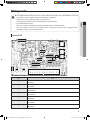
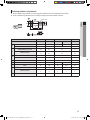
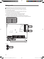
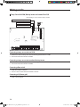
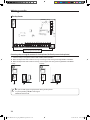
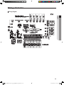
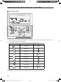
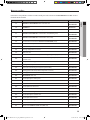
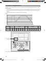
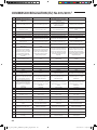
Layout of PCB
SMPS circuit
Micom
LED
EEPROM
2-WIRE COMM
Load control
Fuse
①
②
⑭ ⑬
③
④ ⑤ ⑥ ⑦
⑧ ⑨
⑮
⑩
⑪
⑯
⑰
⑫
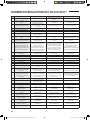
No. Note
①
FR Control
CNS2(Green)
②
Flow Switch
CNS041(Blue)
③
Water Tank
CNS042(Yellow)
④
Heater Out(Mono)
CNS047(Black)
⑤
Mixing Sensor
CNS045(Blue)
⑥
Room Sensor
CNS044(White)
⑦
Smart Grid
CNS046(Red)
9
ENGLISH
EHS MONO Kit-EU_IM_05388A-04_EN.indd 9 2016-06-23 오후 3:42:57

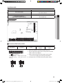
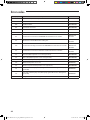
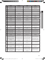
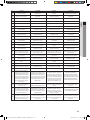
No. Note
⑧
CNS043(White)
1-2:Heater Out
3-4:Eva Out
5-6:Eva in
7-8:Water Out
9-10:Water In
⑨
EEV
CNS062(Blue)
⑩
TB-C (Black)
F3-F4:COMM2 (Wired Remocon)
INPUT/OUTPUT, DC, 210 mA(per each controller)
⑪
TB-C (Black)
F1-F2:COMM1 (IN-OUT COMM)
INPUT/OUTPUT, DC, 10 mA
⑫
CNS1(White)
1:Signal
3:Gnd
⑬
Boost Heater TB-A1 (Black)
L-N, OUTPUT AC
⑭
Main Power TB-A(Black)
L-N, INPUT, AC
⑮
TB-B(Black)
B1: Neutral_INV PUMP, OUTPUT, AC
B2: Mixing Valve_CW, OUTPUT, AC
B3: Mixing Valve_CCW, OUTPUT, AC
B4: Boiler, OUTPUT, AC
B5: Neutral, OUTPUT, AC
B6: Lived_INV PUMP, OUTPUT, AC
B7: Neutral, OUTPUT, AC
B8: Lived, OUTPUT, AC
B9: 2WAY1_NO, OUTPUT, AC
B10: 2WAY1_NC, OUTPUT, AC
B11: Neutral, OUTPUT, AC
B12: Lived, OUTPUT, AC
B13: 2WAY2_NO, OUTPUT, AC
B14: 2WAY2_NC, OUTPUT, AC
B15: Neutral, OUTPUT, AC
B16: Lived, OUTPUT, AC
B17: 3WAY_NO, OUTPUT, AC
B18: 3WAY_NC, OUTPUT, AC
B19: Neutral, OUTPUT, AC
B20: Lived, OUTPUT, AC
B21: THERM01_C, INPUT, AC
B22: THERM01_H, INPUT, AC
B23: THERM02_C, INPUT, AC
B24: THERM02_H, INPUT, AC
B25: Solar/Thermostat_N, INPUT, AC
B26: Solar/Thermostat_L, INPUT, AC
⑯
CNS304(RED)
F3-F4:COMM2 (Wired Remote controller)
⑰
CNS3(Black)
1:Signal
2:Gnd
Wiring works
10
EHS MONO Kit-EU_IM_05388A-04_EN.indd 10 2016-06-23 오후 3:42:58

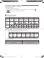
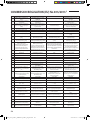
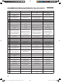
Selecting solderless ring terminal
Select a solderless ring terminal of a connecting power cable based on a nominal dimensions for cable.
Cover a solderless ring terminal and a connector part of the power cable and then connect it.
Silver solder
Nominal dimensions for cable (mm) 1.5 2.5 4/6 10
Nominal dimensions for screw (mm) 4 4 4 8 8
B
Standard dimension (mm) 8 9.5 9.5 12 12
Allowance (mm) ±0.2 ±0.2 ±0.2 ±0.2
D
Standard dimension (mm) 3.4 4.2 5.6 7.1
Allowance (mm)
+0.3
-0.2
+0.3
-0.2
+0.3
-0.2
+0.3
-0.2
d1
Standard dimension (mm) 1.7 2.3 3.4 4.5
Allowance (mm) ±0.2 ±0.2 ±0.2 ±0.2
E Min. 4.1 4.1 6 7.9
F Min. 6 7 5 9 9
L Max. 16 17.5 20 28.5 30
d2
Standard dimension (mm) 4.3 5.3 4.3 8.4 8.4
Allowance (mm)
+ 0.2
0
+ 0.2
0
+ 0.2
0
+0.4
0
+0.4
0
t Min. 0.7 0.8 0.9 1.15
11
ENGLISH
EHS MONO Kit-EU_IM_05388A-04_EN.indd 11 2016-06-23 오후 3:42:58

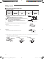
Wiring works
How to connect your extended power cables
1. Prepare the following tools.
Tools Crimping pliers Connection sleeve (mm) Insulation tape Contraction tube (mm)
Spec MH-14 20xØ6.5(HxOD) Width 19mm 70xØ8.0(LxOD)
Shape
2. As shown in the gure, peel o the shields from the rubber and wire of the
power cable.
- Peel o 20 mm of cable shields from the pre-installed tube.
• For information about the power cable specications for indoor and
outdoor units, refer to the installation manual.
• After peeling o cable wires from the pre-installed tube, insert a
contraction tube.
CAUTION
Pre-installed tube for the power cable
(Unit: mm)
Power cable
3. Insert both sides of core wire of the power cable into the connection sleeve.
Method 1
Push the core wire into the sleeve from both sides.
Connection sleeve
Method 2
Twist the wire cores together and push it into the sleeve.
Connection sleeve
4. Using a crimping tool, compress the two points and ip it over and compress another two points in the same location.
- The compression dimension should be 8.0.
- After compressing it, pull both sides of the wire to make sure it is rmly pressed.
Compression
dimension
Method 1
Compress it 4 times.
5 mm
Method 2
Compress it 4 times.
5 mm
12
EHS MONO Kit-EU_IM_05388A-04_EN.indd 12 2016-06-23 오후 3:42:58

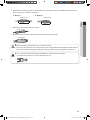
5. Wrap it with the insulation tape twice or more and position your contraction tube in the middle of the insulation tape.
Three or more layers of insulation are required.
Method 1
40 mm
Insulation tape
Method 2
Insulation tape
35 mm
6. Apply heat to the contraction tube to contract it.
Contraction tube
7. After tube contraction work is completed, wrap it with the insulation tape to nish.
Insulation tape
• Make sure that the connection parts are not exposed to outside.
• Be sure to use insulation tape and a contraction tube made of approved reinforced insulating materials that have
the same level of withstand voltage with the power cable. (Comply with the local regulations on extensions.)
CAUTION
• In case of extending the electric wire, please DO NOT use a round-shaped Pressing socket.
- Incomplete wire connections can cause electric shock or a re.
WARNING
13
ENGLISH
EHS MONO Kit-EU_IM_05388A-04_EN.indd 13 2016-06-23 오후 3:42:58

Wiring works
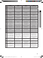
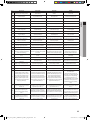
Selection for the power and booster heater wire terminal
Connect the cables to the terminal board using the solderless ring terminal.
Use certied and veried cables.
Connect using a driver which is able to apply the rated torque to the screws.
If the terminal is loose, re may occur caused by arc.
If the terminal is connected too rmly, the terminal may be damaged.
External force should not be applied to the terminal block and wires.
The cable ties to fasten the wire should be an incombustible material, V0 or above.
(The cable ties should be used to fasten the power wire and they are supplied with the unit.)
Tightening Torque (kgf • cm)
M3 0.5 ~ 0.75
M3.5 8 ~ 12
M4 12 ~ 18
M5 20 ~ 30
Main PCB
M4 Screw
M3.5 Screw
M3.5 Screw
M3 Screw
ELCB
M5 Screw
14
EHS MONO Kit-EU_IM_05388A-04_EN.indd 14 2016-06-23 오후 3:42:59

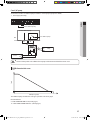
Grounding work
Grounding must be done by a qualied installer for your safety.
Grounding the power cable
The standard of grounding may vary according to the rated voltage and installation place of a heating pump.
Ground the power cable according to the following.
Installation place
Power condition
High humidity Average humidity Low humidity
Electrical potential of lower than 150V
Perform the grounding
work 3.
Note 1)
Perform the grounding work 3 if
possible for your safety.
Note 1)
Electrical potential of higher than 150V
Must perform the grounding work 3.
Note 1)
(In case of installing circuit breaker)
Note 1) Grounding work 3
• Grounding must be done by your installation specialist.
• Check if the grounding resistance is lower than 100Ω.
When installing a circuit breaker that can cut the electric circuit in case of a short circuit, the allowable grounding
resistance can be 30~500Ω.
Examples to use cable striper
<Cable striper>
1. Adjust the blade position by coin(the controller is at the bottom side of the tool). Fix the
blade position according to the outer sheath thickness of the power cable.
2. Fix the power cable and tool by using the hook at the top side of the tool.
3. Cut out the outer sheath of the power cable by revolving the tool in the direction of the
arrow, two or three times.
4. At this situation, cut out the outer sheath of the power cable by moving the tool toward
the arrow direction expressed.
5. Slightly bend the wire and pull out the cut part of the outer sheath.
15
ENGLISH
EHS MONO Kit-EU_IM_05388A-04_EN.indd 15 2016-06-23 오후 3:42:59

Wiring works
Power and communication with outdoor unit
Power Wire
ELCB
Communication
Wire
N L
• Be careful when connecting L, N.
CAUTION
Connecting the power wire
1. Connect ‘Live’ and 'Neutral’ power line with ‘L, N’ of a ELCB.
2. Connect ‘L,N’ of a ELCB with ‘A1 and A2’ in TB-A.
3. Connect ‘Protective Earth’ line with ‘Earth screw’ In case.
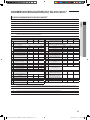
Recommended wire specication
Load Power Supply
Power Cable Max. Length
mm
2
, wires m
Do NOT use Heater (Water Pump,
Valve, Wired RMC)
1Ø, 220-240V, 50Hz
1.5 / 3 L < 10m
2.5 / 3 10m < L
Use Booster Heater (Max. 3kW)
4.0 / 3 L < 10m
6.0 / 3 10m < L
The power cable is not supplied with Air to water heat pump.
This equipment with "IEC 61000-3-12".
Supply cords of parts of appliances for control kit use shall not be lighter than polychloroprene sheathed exible cord
(Code designation IEC:60245 IEC 57 / CENELEC:H05RN-F)
16
EHS MONO Kit-EU_IM_05388A-04_EN.indd 16 2016-06-23 오후 3:43:00

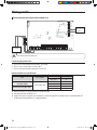
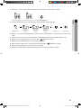
Connecting the communication wire
Connect ‘outdoor unit’s F1&F2’ with ‘control kit’s F1&F2 in TB-C’ by 2 core cable.
Outdoor Unit
(at Control Plate)
Control Kit
Communication with a wired remote controller (1 unit)
Wired Remote Controller
(Master)
Communication with a wired remote controller (2 units)
Wired Remote Controller
(Slave)
Wired Remote Controller
(Master)
Connecting a wired remote controller
1. Connect 'F3, F4' of TB-C kit with 'F3, F4' of a wired remote controller.
2 units (wired remote controllers) are able to be installed on TB-C.
When 2 units are installed, either one shall has "Master" setting and another one shall have "Slave" settings on a wired
remote controller.
17
ENGLISH
EHS MONO Kit-EU_IM_05388A-04_EN.indd 17 2016-06-23 오후 3:43:00

Wiring works
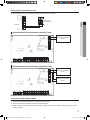
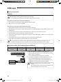
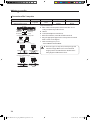
Temp. Sensor for DHW, Backup heater and a water Flow S/W
Relay
External wiring to control a switch of relay by a installer
Temp. sensor for DHW
Flow s/w
Temp. sensor for backup heater
Connecting a temp. sensor wire into DHW
1. Put the sensor side of a temp. sensor wire into the designated location in a DHW.
2. Connect the other side of the line at CNS042.
Connecting a temp. sensor wire to outlet of backup heater
1. Put the sensor side of a temp. sensor wire into the designated location in a backup heater.
2. Connect the other side of the line at CNS047.
Connecting a ow switch
1. Install a ow switch in water line.
2. Connect a wire of a ow switch into 'CNS041' connector.
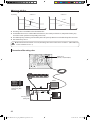
Connecting a S/G(Smart grid)
1. Install as above diagram.
18
EHS MONO Kit-EU_IM_05388A-04_EN.indd 18 2016-06-23 오후 3:43:01

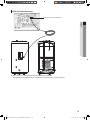
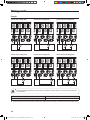
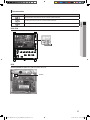
DHW tank Switch box layout
DHW Tank Temp. (15m) CNS042(YEL)
Use a correct sensor pocket which is t for the DHW tank sensor(OD Ø6).
If the gap between the supplied sensor and DHW tank sensor pocket is big, use thermal grease.
19
ENGLISH
EHS MONO Kit-EU_IM_05388A-04_EN.indd 19 2016-06-23 오후 3:43:01

DHW tank
Electrical connections
Procedure
• Switch o the power supply before making any connections.
• Use a thermal grease in thermistor pocket after installing electric connections.
WARNING
Connections to be made in the electrical box of DHW tank
1. Connect the booster heater power supply and thermal protection cable.
2. Make sure to ensure strain relief of the cable.
Connections to be made in the electrical box of indoor units
3. Plug the thermistor cable connector in the connector CNS042 on the pcb.
4. Connect the booster heater power supply and thermal protection cable(eld supply) to terminal TB-A1 and earth on the
terminal block.
5. Connector the loose ends of the TB-A1 on the terminal block and the connector CNS042 on the PCB.
6. Plug the thermistor cable connector in the socket X9A on the PCB.
7. Connect the booster heater power supply and thermal protection cable (eld supply) to terminal 7, 8, 21, 22 and earth on
the terminal block.
8. Connect the booster heater power supply cable to the circuit breaker and earthing screw.
9. Fix the cables to the cable tie mountings with cable ties to ensure strain relief.
• It is of great importance that the heater is lled with water before the electricity is hooked up, or else- the
warranty is not valid. If the heater is installed and not used, it must be ushed with water once a week.
CAUTION
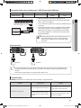
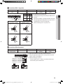
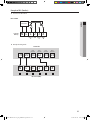
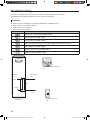
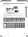
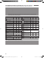
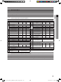
Connection of the solar circulation pump for DHW tank
Description No. of wires Max. A Thickness Supply Scope
Solar pump 2+ground 10 mA
0.75mm
2
H05RN-F or
H07RN-F
Field supply (230V~,
Input)
SOLAR PUMP (L)
SOLAR PUMP (N)
Controller
Solar pump
Power
B25
B26
1. Before the installation, control kit should be turned o.
2. Using the appropriate equipment to correct position of terminal
block as shown on the diagram.
3. It is for control kit to inform that the pump is operating.
4. Solar pump is controlled by installer’s handling. And it send the
signal to control kit depending on solar pump conditions. In
operating mode, signal shall be around 230Vac B/W N&L. In non-
operating mode, signal shall be around 0Vac B/W N&L.
• Maximun allwable current of each terminal is below
10mA.
• Ports number B25, B26 are for input port for detection and
they do not supply power to a solar pump.
CAUTION
20
EHS MONO Kit-EU_IM_05388A-04_EN.indd 20 2016-06-23 오후 3:43:01
La pagina si sta caricando...
La pagina si sta caricando...
La pagina si sta caricando...
La pagina si sta caricando...
La pagina si sta caricando...
La pagina si sta caricando...
La pagina si sta caricando...
La pagina si sta caricando...
La pagina si sta caricando...
La pagina si sta caricando...
La pagina si sta caricando...
La pagina si sta caricando...
La pagina si sta caricando...
La pagina si sta caricando...
La pagina si sta caricando...
La pagina si sta caricando...
La pagina si sta caricando...
La pagina si sta caricando...
La pagina si sta caricando...
La pagina si sta caricando...
La pagina si sta caricando...
La pagina si sta caricando...
La pagina si sta caricando...
La pagina si sta caricando...
La pagina si sta caricando...
La pagina si sta caricando...
La pagina si sta caricando...
La pagina si sta caricando...
La pagina si sta caricando...
La pagina si sta caricando...
La pagina si sta caricando...
La pagina si sta caricando...
La pagina si sta caricando...
La pagina si sta caricando...
La pagina si sta caricando...
La pagina si sta caricando...
La pagina si sta caricando...
La pagina si sta caricando...
La pagina si sta caricando...
La pagina si sta caricando...
La pagina si sta caricando...
La pagina si sta caricando...
La pagina si sta caricando...
La pagina si sta caricando...
La pagina si sta caricando...
La pagina si sta caricando...
La pagina si sta caricando...
La pagina si sta caricando...
La pagina si sta caricando...
La pagina si sta caricando...
La pagina si sta caricando...
La pagina si sta caricando...
La pagina si sta caricando...
La pagina si sta caricando...
La pagina si sta caricando...
La pagina si sta caricando...
-
 1
1
-
 2
2
-
 3
3
-
 4
4
-
 5
5
-
 6
6
-
 7
7
-
 8
8
-
 9
9
-
 10
10
-
 11
11
-
 12
12
-
 13
13
-
 14
14
-
 15
15
-
 16
16
-
 17
17
-
 18
18
-
 19
19
-
 20
20
-
 21
21
-
 22
22
-
 23
23
-
 24
24
-
 25
25
-
 26
26
-
 27
27
-
 28
28
-
 29
29
-
 30
30
-
 31
31
-
 32
32
-
 33
33
-
 34
34
-
 35
35
-
 36
36
-
 37
37
-
 38
38
-
 39
39
-
 40
40
-
 41
41
-
 42
42
-
 43
43
-
 44
44
-
 45
45
-
 46
46
-
 47
47
-
 48
48
-
 49
49
-
 50
50
-
 51
51
-
 52
52
-
 53
53
-
 54
54
-
 55
55
-
 56
56
-
 57
57
-
 58
58
-
 59
59
-
 60
60
-
 61
61
-
 62
62
-
 63
63
-
 64
64
-
 65
65
-
 66
66
-
 67
67
-
 68
68
-
 69
69
-
 70
70
-
 71
71
-
 72
72
-
 73
73
-
 74
74
-
 75
75
-
 76
76


Samsung MIM-E03AN Guida utente
- Tipo
- Guida utente
- Questo manuale è adatto anche per
in altre lingue
- English: Samsung MIM-E03AN User guide
- slovenčina: Samsung MIM-E03AN Užívateľská príručka
- română: Samsung MIM-E03AN Manualul utilizatorului
Documenti correlati
Altri documenti
-
LG HU091.U43 Manuale del proprietario
-
-
LG HU163.U33 Manuale del proprietario
-
-
-
LG HM071M.U43 Manuale del proprietario
-
-
-
Panasonic WHADC1216H6E5C Istruzioni per l'uso
-
Gorenje TC100ZNT Manuale del proprietario