Hitachi RAI-50PPD Istruzioni per l'uso
- Categoria
- Condizionatori d'aria a sistema split
- Tipo
- Istruzioni per l'uso
Questo manuale è adatto anche per

INDOOR UNITS SYSTEM
RAI-50PPD, RAI-60PPD
INSTALLATION AND OPERATION MANUAL
MANUAL DE INSTALACIÓN Y FUNCIONAMIENTO
INSTALLATIONS- UND BETRIEBSHANDBUCH
MANUEL D’INSTALLATION ET DE FONCTIONNEMENT
MANUALE D’INSTALLAZIONE E D’USO
MANUAL DE INSTALAÇÃO E DE FUNCIONAMENTO
INSTALLATIONS- OG BETJENINGSVEJLEDNING
INSTALLATIE- EN BEDIENINGSHANDLEIDING
INSTALLATION- OCH DRIFTHANDBOK
ΕΓΧΕΙΡΙΔΙΟ ΕΓΚΑΤΑΣΤΑΣΗΣ ΚΑΙ ΛΕΙΤΟΥΡΓΙΑΣ
4-way cassette - R32


English
Specications in this manual are subject to change without notice in order that HITACHI may bring the latest innovations to their
customers.
Whilst every effort is made to ensure that all specications are correct, printing errors are beyond HITACHI’s control; HITACHI
cannot be held responsible for these errors.
Español
Las especicaciones de este manual están sujetas a cambios sin previo aviso a n de que HITACHI pueda ofrecer las últimas
innovaciones a sus clientes.
A pesar de que se hacen todos los esfuerzos posibles para asegurarse de que las especicaciones sean correctas, los errores
de impresión están fuera del control de HITACHI, a quien no se hará responsable de ellos.
Deutsch
Bei den technischen Angaben in diesem Handbuch sind Änderungen vorbehalten, damit HITACHI seinen Kunden die jeweils
neuesten Innovationen präsentieren kann.
Sämtliche Anstrengungen wurden unternommen, um sicherzustellen, dass alle technischen Informationen ohne Fehler
veröffentlicht worden sind. Für Druckfehler kann HITACHI jedoch keine Verantwortung übernehmen, da sie außerhalb ihrer
Kontrolle liegen.
Français
Les caractéristiques publiées dans ce manuel peuvent être modiées sans préavis, HITACHI souhaitant pouvoir toujours offrir à
ses clients les dernières innovations.
Bien que tous les efforts sont faits pour assurer l’exactitude des caractéristiques, les erreurs d’impression sont hors du contrôle
de HITACHI qui ne pourrait en être tenu responsable.
Italiano
Le speciche di questo manuale sono soggette a modica senza preavviso afnché HITACHI possa offrire ai propri clienti le
ultime novità. Sebbene sia stata posta la massima cura nel garantire la correttezza dei dati, HITACHI non è responsabile per
eventuali errori di stampa che esulano dal proprio controllo.
Português
As especicações apresentadas neste manual estão sujeitas a alterações sem aviso prévio, de modo a que a HITACHI possa
oferecer aos seus clientes, da forma mais expedita possível, as inovações mais recentes.
Apesar de serem feitos todos os esforços para assegurar que todas as especicações apresentadas são correctas, quaisquer
erros de impressão estão fora do controlo da HITACHI, que não pode ser responsabilizada por estes erros eventuais.
Dansk
Specikationerne i denne vejledning kan ændres uden varsel, for at HITACHI kan bringe de nyeste innovationer ud til kunderne.
På trods af alle anstrengelser for at sikre at alle specikationerne er korrekte, har HITACHI ikke kontrol over trykfejl, og HITACHI
kan ikke holdes ansvarlig herfor.
Nederlands
De specicaties in deze handleiding kunnen worden gewijzigd zonder verdere kennisgeving zodat HITACHI zijn klanten kan
voorzien van de nieuwste innovaties.
Iedere poging wordt ondernomen om te zorgen dat alle specicaties juist zijn. Voorkomende drukfouten kunnen echter niet door
HITACHI worden gecontroleerd, waardoor HITACHI niet aansprakelijk kan worden gesteld voor deze fouten.
Svenska
Specikationerna i den här handboken kan ändras utan föregående meddelande för att HITACHI ska kunna leverera de senaste
innovationerna till kunderna.
Vi på HITACHI gör allt vi kan för att se till att alla specikationer stämmer, men vi har ingen kontroll över tryckfel och kan därför
inte hållas ansvariga för den typen av fel.
Eλλhnika
Οι προδιαγραφές του εγχειριδίου μπορούν να αλλάξουν χωρίς προειδοποίηση, προκειμένου η HITACHI να παρέχει τις
τελευταίες καινοτομίες στους πελάτες της.
Αν και έχει γίνει κάθε προσπάθεια προκειμένου να εξασφαλιστεί ότι οι προδιαγραφές είναι σωστές, η HITACHI δεν μπορεί να
ελέγξει τα τυπογραφικά λάθη και, ως εκ τούτου, δεν φέρει καμία ευθύνη για αυτά τα λάθη.

! CAUTION
This product shall not be mixed with general house waste at the end of its life and it shall be retired according to the
appropriated local or national regulations in a environmentally correct way.
Due to the refrigerant, oil and other components contained in Air Conditioner, its dismantling must be done by a profes-
sional installer according to the applicable regulations. Contact to the corresponding authorities for more information.
! PRECAUCIÓN
Éste producto no se debe eliminar con la basura doméstica al nal de su vida útil y se debe desechar de manera respetuosa con el medio
ambiente de acuerdo con los reglamentos locales o nacionales aplicables.
Debido al refrigerante, el aceite y otros componentes contenidos en el sistema de aire acondicionado, su desmontaje debe realizarlo un
instalador profesional de acuerdo con la normativa aplicable. Para obtener más información, póngase en contacto con las autoridades
competentes.
! VORSICHT
Dass Ihr Produkt am Ende seiner Betriebsdauer nicht in den allgemeinen Hausmüll geworfen werden darf, sondern entsprechend den
geltenden örtlichen und nationalen Bestimmungen auf umweltfreundliche Weise entsorgt werden muss.
Aufgrund des Kältemittels, des Öls und anderer in der Klimaanlage enthaltener Komponenten muss die Demontage von einem Fachmann
entsprechend den geltenden Vorschriften durchgeführt werden.
Für weitere Informationen setzen Sie sich bitte mit den entsprechenden Behörden in Verbindung.
! PRECAUTION
Ne doit pas être mélangé aux ordures ménagères ordinaires à la n de sa vie utile et qu’il doit être éliminé conformément à la réglementa-
tion locale ou nationale, dans le plus strict respect de l’environnement.
En raison du frigorigène, de l’huile et des autres composants que le climatiseur contient, son démontage doit être réalisé par un instal-
lateur professionnel conformément aux réglementations en vigueur.
! ATTENZIONE
Indicazioni per il corretto smaltimento del prodotto ai sensi della Direttiva Europea 2002/96/EC e Dlgs 25 luglio 2005 n.151
Il simbolo del cassonetto barrato riportato sull’ apparecchiatura indica che il prodotto alla ne della propria vita utile deve essere raccolto
separatamente dagli altri riuti.
L’utente dovrà, pertanto, conferire l’apparecchiatura giunta a ne vita agli idonei centri di raccolta differenziata dei riuti elettronici ed
elettrotecnici, oppure riconsegnarla al rivenditore al momento dell’ acquisto di una nuova apparecchiatura di tipo equivalente.
L’adeguata raccolta differenziata delle apparecchiature dismesse, per il loro avvio al riciclaggio, al trattamento ed allo smaltimento ambi-
entalmente compatibile, contribuisce ad evitare possibili effetti negativi sull’ ambiente e sulla salute e favorisce il riciclo dei materiali di cui
è composta l’ apparecchiatura.
Non tentate di smontare il sistema o l’unità da soli poichè ciò potrebbe causare effetti dannosi sulla vostra salute o sull’ ambiente.
Vogliate contattare l’ installatore, il rivenditore, o le autorità locali per ulteriori informazioni.
Lo smaltimento abusivo del prodotto da parte dell’utente può comportare l’applicazione delle sanzioni amministrative di cui all’articolo 50
e seguenti del D.Lgs. n. 22/1997.
! CUIDADO
O seu produto não deve ser misturado com os desperdícios domésticos de carácter geral no nal da sua duração e que deve ser elimi-
nado de acordo com os regulamentos locais ou nacionais adequados de uma forma correcta para o meio ambiente.
Devido ao refrigerante, ao óleo e a outros componentes contidos no Ar condicionado, a desmontagem deve ser realizada por um insta-
lador prossional de acordo com os regulamentos aplicáveis. Contacte as autoridades correspondentes para obter mais informações.
! BEMÆRK:
At produktet ikke må smides ud sammen med almindeligt husholdningsaffald, men skal bortskaffes i overensstemmelse med de gæl-
dende lokale eller nationale regler på en miljømæssig korrekt måde.
Da klimaanlægget indeholder kølemiddel, olie samt andre komponenter, skal afmontering foretages af en fagmand i overensstemmelse
med de gældende bestemmelser. Kontakt de pågældende myndigheder for at få yderligere oplysninger.
! FORSIGTIG
Dit houdt in dat uw product niet wordt gemengd met gewoon huisvuil wanneer u het weg doet en dat het wordt gescheiden op een milieu-
vriendelijke manier volgens de geldige plaatselijke en landelijke reguleringen.
Vanwege het koelmiddel, de olie en andere onderdelen in de airconditioner moet het apparaat volgens de geldige regulering door een
professionele installateur uit elkaar gehaald worden.
Neem contact op met de betreffende overheidsdienst voor meer informatie.
! LET OP
Det innebär att produkten inte ska slängas tillsammans med vanligt hushållsavfall utan kasseras på ett miljövänligt sätt i enlighet med
gällande lokal eller nationell lagstiftning.
Luftkonditioneringsaggregatet innehåller kylmedium, olja och andra komponenter, vilket gör att det måste demonteras av en fackman i
enlighet med tillämpliga regelverk. Ta kontakt med ansvarig myndighet om du vill ha mer information.
! ΠΡΟΣΟΧΗ
Σημαίνει ότι το προϊόν δεν θα πρέπει να αναμιχθεί με τα διάφορα οικιακά απορρίμματα στο τέλος του κύκλου ζωής του και θα πρέπει να
αποσυρθεί σύμφωνα με τους κατάλληλους τοπικούς ή εθνικούς κανονισμούς και με τρόπο φιλικό προς το περιβάλλον.
Λόγω του ψυκτικού, του λαδιού και άλλων στοιχείων που περιέχονται στο κλιματιστικό, η αποσυναρμολόγησή του πρέπει να γίνει από
επαγγελματία τεχνικό και σύμφωνα με τους ισχύοντες κανονισμούς. Για περισσότερες λεπτομέρειες, επικοινωνήστε με τις αντίστοιχες αρχές.

!
DANGER – Hazards or unsafe practices which COULD result in severe personal injuries or death.
PELIGRO – Riesgos o prácticas poco seguras que PODRÍAN producir lesiones personales e incluso la muerte.
GEFAHR – Gefährliche oder unsichere Anwendung, die zu schweren Körperverletzungen oder zum Tod führen kann.
DANGER – Utilisation dangereuse ou sans garantie de sécurité qui PEUT provoquer de sévères blessures personnelles ou la
mort.
PERICOLO – Pericoli o azioni pericolose che POTREBBERO avere come esito lesioni siche gravi o il decesso.
PERIGO – Riesgos o prácticas poco seguras que PUEDEN producir lesiones personales e incluso la muerte
FARE – Farer eller farlig brug, som KAN resultere i alvorlig personskade eller dødsfald.
GEVAAR – Gevaren of onveilige praktijken die ernstig persoonlijk letsel of de dood tot gevolg KUNNEN hebben.
FARA – Risker eller osäkra tillvägagångssätt som KAN leda till svåra personskador eller dödsfall.
KINAYNO – Κίνδυνοι ή επικίνδυνες πρακτικές, οι οποίες ΜΠΟΡΕΙ να έχουν ως αποτέλεσµα σοβαρές σωµατικές βλάβες ή
θάνατο.
!
CAUTION – Hazards or unsafe practices which COULD result in minor personal injury or product or property damage.
PRECAUCIÓN – Riesgos o prácticas poco seguras que PODRÍAN provocar lesiones personales de menor importancia o daños
en el producto u otros bienes.
VORSICHT – Gefährliche oder unsichere Anwendung, die geringfügigen Personen-, Produkt- oder Sachschaden verursachen
kann.
PRECAUTION – Utilisation dangereuse ou sans garantie de sécurité qui PEUT provoquer des blessures mineures ou des
dommages au produit ou aux biens.
ATTENZIONE – Pericoli o azioni pericolose che POTREBBERO avere come esito lesioni siche minori o danni al prodotto o ad
altri beni.
CUIDADO – Perigos e procedimentos perigosos que PODERÃO PROVOCAR danos pessoais ligeiros ou danos em produtos e
bens.
FORSIGTIG – Farer eller farlig brug, som KAN resultere i mindre skade på personer, produkt eller ejendom.
LET OP – Gevaren of onveilige praktijken die licht persoonlijk letsel of beschadiging van het product of eigendommen tot gevolg
KUNNEN hebben.
VARNING – Risker eller farliga tillvägagångssätt som KAN leda till mindre personskador eller skador på produkten eller på
egendom.
ΠΡΟΣΟΧΗ – Κίνδυνοι ή επικίνδυνες πρακτικές, οι οποίες ΜΠΟΡΕΙ να έχουν ως αποτέλεσµα την πρόκληση ελαφρών
σωµατικών βλαβών ή καταστροφή περιουσίας.
?
NOTE – The text following this symbol contains information or instructions that may be of use or that require a more thorough
explanation.
NOTA – El texto que sigue a este símbolo contiene información o instrucciones que pueden ser de utilidad o requeridas para
ampliar una explicación.
HINWEIS – Der diesem Symbol folgende Text enthält konkrete Informationen und Anleitungen, die nützlich sein können oder
eine tiefergehende Erklärung benötigen.
REMARQUE – Les textes précédés de ce symbole contiennent des informations ou des indications qui peuvent être utiles, ou
qui méritent une explication plus étendue.
NOTA – I testi preceduti da questo simbolo contengono informazioni o indicazioni che possono risultare utili o che meritano una
spiegazione più estesa.
NOTA – Os textos precedidos deste símbolo contêm informações ou indicações que podem ser úteis, ou que merecem uma
explicação mais detalhada.
BEMÆRK – Den tekst, der følger efter dette symbol, indeholder oplysninger eller anvisninger, der kan være til nytte, eller som
kræver en mere grundig forklaring.
OPMERKING – De teksten waar dit symbool voorstaat bevatten nuttige informatie en aanwijzingen, of informatie en
aanwijzingen meer uitleg behoeven.
OBS – Texten efter denna symbol innehåller information och anvisningar som kan vara användbara eller som kräver en
noggrannare förklaring.
ΣΗΜΕΙΩΣΗ – Το κείμενο που ακολουθεί αυτό το σύμβολο περιέχει πληροφορίες ή οδηγίες που μπορεί να φανούν χρήσιμες ή
που απαιτούν μια πιο ενδελεχή εξήγηση.

This product contains biocidal substances according to EU Reg. 528/2012
Este producto contiene sustancias biocidas según el Reg. UE 528/2012
Dieses Produkt enthält Biozide nach EU Verordnung 528/2012
Conformément à la Reg UE 528/2012, ce produit contient des substances biocides
Questo prodotto contiene sostanze biocidi ai sensi del Reg. UE 528/2012
Este produto contém substâncias biocidas de acordo com o Regulamento (UE) N.º 528/2012
Dette produkt indeholder biocider i henhold til EU-forordning nr. 528/2012
Dit product bevat biociden volgens Europese Richtlijn 528/2012.
Denna produkt innehåller biocider i enlighet med den europeiska förordningen 528/2012
Αυτό το προϊόν περιλαμβάνει βιοκτόνες ουσίες σύμφωνα με το κανονισμό ΕΕ 528/2012
Biocide property/Propiedad biocida/Biozide Eigenschaft/Propriété biocide/Proprietà biocida/Propriedade biocida/
Biocide egenskaber/Biocide eigenschappen/Biocidegenskaper/Ιδιότητα του βιοκτόνου:
Antibacterial / Antibacteriana / Antibactérienne / Antibatterica / Antibakterielle / Antibacteriana / Antibakterielle /
Antibacteriëel / Antibakteriellt /Αντιβακτηριακές
Active substance/Sustancia activa/Aktivstoffe/ Substances actives/Principi attivi/ Substância ativa/Virksomt stof/
Actieve stof/Verksamt ämne/ Δραστική ουσία:
Silver / Plata / Silver / Argent / Argento / Prata / Sølv / Zilver / Silver / Άργυρος CAS Nº: 7440-22-4
These substances are NOT harmful to human health nor the environment
Estas sustancias no son perjudiciales para la salud humana ni el medio ambiente
Diese Stoffe sind nicht schädlich für die menschliche Gesundheit noch Umwelt
Ces substances ne sont pas nocives pour la santé humaine ni pour l’environnement
Queste sostanze non sono nocive per la salute umana o per l’ambiente
Estas substâncias NÃO são prejudiciais para a saúde humana nem para o ambiente
Disse stoffer er IKKE skadelige for hverken menneskers sundhed eller for miljøet
Deze stoffen zijn NIET schadelijk voor de menselijke gezondheid of voor het milieu.
Dessa ämnen är INTE skadliga för människors hälsa eller för miljön.
Αυτές οι ουσίες ΔΕΝ είναι επιβλαβείς στην ανθρώπινη υγεία ή στο περιβάλλον
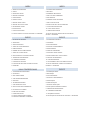
Note
●
The recommended temperatures range for safety testing should be as below:
Minimum Maximum Minimum
Indoor Dry bulb °C 21 32 20 27
Wet bulb °C 15 23 12 19
Outdoor Dry bulb °C
21
43 2 21
Wet bulb °C
15
26 1 15
Cooling Heating
Maximum

INDEX
1 GENERAL INFORMATION
2 SAFETY
3 IMPORTANT NOTICE
4 BEFORE OPERATION
5 MAINTENANCE
6 NAME OF PARTS
7 BEFORE INSTALLATION
8 INDOOR UNIT INSTALLATION
9 REFRIGERANT PIPING
10 DRAIN PIPING
11 ELECTRICAL WIRING
12 INSTALLATION OF OPTIONAL AIR PANEL: P-AP56NAMS
ÍNDICE
1 INFORMACIÓN GENERAL
2 SEGURIDAD
3 AVISO IMPORTANTE
4 ANTES DEL FUNCIONAMIENTO
5 MANTENIMIENTO
6 NOMBRE DE LOS COMPONENTES
7 ANTES DE LA INSTALACIÓN
8 INSTALACIÓN DE LA UNIDAD INTERIOR
9 TUBERÍA DE REFRIGERANTE
10 TUBERÍA DE DESAGÜE
11 CABLEADO ELÉCTRICO
12 INSTALACIÓN DEL PANEL DE AIRE OPCIONAL:
P-AP56NAMS
INHALTSVERZEICHNIS
1 ALLGEMEINE INFORMATIONEN
2 SICHERHEIT
3 WICHTIGER HINWEIS
4 VOR DER INBETRIEBNAHME
5 WARTUNG
6 TEILEBEZEICHNUNGEN
7 VOR DER INSTALLATION
8 INSTALLATION DES INNENGERÄTS
9 KÄLTEMITTELLEITUNGEN
10 ABFLUSSLEITUNGEN
11 KABELANSCHLUSS
12 INSTALLATION DER OPTIONALEN
LUFTAUSTRITTSBLENDE: P-AP56NAMS
INDEX
1 INFORMATIONS GÉNÉRALES
2 SÉCURITÉ
3 REMARQUE IMPORTANTE
4 AVANT LE FONCTIONNEMENT
5 MAINTENANCE
6 NOMENCLATURE DES PIÈCES
7 AVANT L'INSTALLATION
8 INSTALLATION DE L’UNITÉ INTÉRIEURE
9 TUYAUTERIE FRIGORIFIQUE
10 TUYAU D'ÉVACUATION
11 CÂBLAGE ÉLECTRIQUE
12 INSTALLATION DU PANNEAU DE SOUFFLAGE EN
OPTION : P-AP56NAMS
INDICE
1 INFORMAZIONI GENERALI
2 SICUREZZA
3 NOTA IMPORTANTE
4 PRIMA DEL FUNZIONAMENTO
5 MANUTENZIONE
6 NOME DEI COMPONENTI
7 PRIMA DELL'INSTALLAZIONE
8 INSTALLAZIONE DELL’UNITÀ INTERNA
9 LINEA DEL REFRIGERANTE
10 LINEA DI DRENAGGIO
11 COLLEGAMENTO DELLO SCHEMA ELETTRICO
12 INSTALLAZIONE DEL PANNELLO DI MANDATA
PZIONALE: P-AP56NAMS
ÍNDICE
1 INFORMAÇÃO GERAL
2 SEGURANÇA
3 NOTA IMPORTANTE
4 ANTES DO FUNCIONAMENTO
5 MANUTENÇÃO
6 NOME DAS PEÇAS
7 ANTES DA INSTALAÇÃO
8 INSTALAÇÃO DA UNIDADE INTERIOR
9 TUBAGEM DE REFRIGERANTE
10 TUBAGEM DE DESCARGA
11 LIGAÇÕES ELÉTRICAS
12 INSTALAÇÃO DO PAINEL DE AR OPCIONAL: P-AP56NAMS

INDHOLDSFORTEGNELSE
1 GENEREL INFORMATION
2 SIKKERHED
3 VIGTIG INFORMATION
4 FØR DRIFT
5 VEDLIGEHOLDELSE
6 NAVN PÅ DELE
7 INDEN MONTERING
8 MONTERING AF INDENDØRSENHED
9 KØLEMIDDELRØR
10 AFLØBSRØR
11 ELEKTRISK LEDNINGSFØRING
12 MONTERING AF UDLUFTNINGSPANEL (VALGFRIT
TILBEHØR): P-AP56NAMS
INHOUDSOPGAVE
1 ALGEMENE INFORMATIE
2 VEILIGHEID
3 BELANGRIJKE MEDEDELING
4 VOORDAT U HET SYSTEEM IN GEBRUIK NEEMT
5 ONDERHOUD
6 NAAM ONDERDELEN
7 VÓÓR INSTALLATIE
8 DE BINNENUNIT INSTALLEREN
9 KOUDEMIDDELLEIDING
10 AFVOERLEIDING
11 ELEKTRISCHE BEDRADING
12 HET OPTIONELE LUCHTPANEEL INSTALLEREN:
P-AP56NAMS
INNEHÅLLSFÖRTECKNING
1 ALLMÄN INFORMATION
2 SÄKERHET
3 VIKTIGT MEDDELANDE
4 FÖRE ANVÄNDNING
5 UNDERHÅLL
6 DELARNAS NAMN
7 FÖRE MONTERING
8 INSTALLATION AV INOMHUSENHET
9 KYLRÖR
10 DRÄNERINGSRÖR
11 ELEKTRISK ANSLUTNING
12 INSTALLATION AV EXTRA LUFTPANEL: P-AP56NAMS
ΕΥΡΕΤΗΡΙΟ
1 ΓΕΝΙΚΕΣ ΠΛΗΡΟΦΟΡΙΕΣ
2 ΑΣΦΑΛΕΙΑ
3 ΣΗΜΑΝΤΙΚΗ ΠΑΡΑΤΗΡΗΣΗ
4 ΠΡΙΝ ΑΠΟ ΤΗ ΛΕΙΤΟΥΡΓΙΑ
5 ΣΥΝΤΗΡΗΣΗ
6 ΟΝΟΜΑΤΑ ΕΞΑΡΤΗΜΑΤΩΝ
7 ΠΡΙΝ ΤΗΝ ΕΓΚΑΤΑΣΤΑΣΗ
8 ΕΓΚΑΤΑΣΤΑΣΗ ΕΣΩΤΕΡΙΚΗΣ ΜΟΝΑΔΑΣ
9 ΣΩΛΗΝΩΣΕΙΣ ΨΥΚΤΙΚΟΥ ΜΕΣΟΥ
10 ΣΩΛΗΝΩΣΗ ΑΠΟΧΕΤΕΥΣΗΣ
11 ΗΛΕΚΤΡΙΚΗ ΚΑΛΩΔΙΩΣΗ
12 ΕΓΚΑΤΑΣΤΑΣΗ ΤΟΥ ΠΡΟΑΙΡΕΤΙΚΟΥ ΣΤΟΜΙΟΥ ΑΕΡΑ:
P-AP56NAMS
EN English Original version
ES Español Versión traducida
DE Deutsch Übersetzte Version
FR Français Version traduite
IT Italiano Versione tradotta
PT Português Versão traduzidal
DA Dansk Oversat version
NL Nederlands Vertaalde versie
SV Svenska Översatt version
EL Ελληνικα Μεταφρασμένη έκδοση

ENGLISH
1 GENERAL INFORMATION
1.1 GENERAL NOTES
No part of this publication may be reproduced, copied, led
or transmitted in any shape or form without the permission of
Johnson Controls-Hitachi Air Conditioning Spain, S.A.U.
Within the policy of continuous improvement of its products,
Johnson Controls-Hitachi Air Conditioning Spain, S.A.U.
reserves the right to make changes at any time without prior
notication and without being compelled to introducing them into
products subsequently sold. This document may therefore have
been subject to amendments during the life of the product.
HITACHI makes every effort to offer correct, up-to-date
documentation. Despite this, printing errors cannot be controlled
by HITACHI and are not its responsibility.
As a result, some of the images or data used to illustrate this
document may not refer to specic models. No claims will be
accepted based on the data, illustrations and descriptions
included in this manual.
No type of modication must be made to the equipment without
prior, written authorisation from the manufacturer.
1.2 PRODUCT GUIDE
1.2.1 Prior check
? NOTE
Check, depending on the name of the model, the type of air conditioning
system tted, the abbreviated code and reference in this instruction
manual. This Installation and Operating Manual only refers to
RAI-(50/60)PPD units.
Check, in accordance with the Installation and Operating Manuals
included with the outdoor and indoor units, that all the information
necessary for the correct installation of the system is included. If this is
not the case, please contact your distributor.
2 SAFETY
This appliance is lled with R32
2.1 SYMBOLS USED
During normal air conditioning system design work or unit
installation, greater attention must be paid in certain situations
requiring particular care in order to avoid injuries and damage to
the unit, the installation or the building or property.
Situations that jeopardise the safety of those in the surrounding
area or that put the unit itself at risk will be clearly indicated in
this manual.
To indicate these situations, a series of special symbols will be
used to clearly identify these situations.
Pay close attention to these symbols and to the messages
following them, as your safety and that of others depends on it.
! DANGER
• The text following this symbol contains information and
instructions relating directly to your safety and physical
wellbeing.
• Not taking these instructions into account could lead to serious,
very serious or even fatal injuries to you and others in the
proximities of the unit.
In the texts following the danger symbol you can also nd
information on safe procedures during unit installation.
! CAUTION
• The text following this symbol contains information and instructions
relating directly to your safety and physical wellbeing.
• Not taking these instructions into account could lead to minor injuries
to you and others in the proximities of the unit.
• Not taking these instructions into account could lead to unit damage.
In the texts following the caution symbol you can also nd
information on safe procedures during unit installation.
? NOTE
• The text following this symbol contains information or instructions that
may be of use or that require a more thorough explanation.
• Instructions regarding inspections to be made on unit parts or systems
may also be included.
GENERAL INFORMATION
PMML0477 rev.0 - 07/2017
1

2.2 ADDITIONAL INFORMATION ABOUT SAFETY
! DANGER
• HITACHI is not able to foresee all the circumstances which may
result in a potential danger.
• Do not pour water in the indoor or outdoor unit. These products
are tted with electric components. If water comes into contact
with electric components, this will cause a serious electric
shock.
• Do not handle or adjust the safety devices inside the indoor and
outdoor units. The handling or adjustment of these devices may
result in serious accident.
• Do not open the service cover or access panel of the indoor and
outdoor units without disconnecting the main supply.
• In the event of re, switch off the mains, put out the re
immediately and contact your service supplier.
• Check that the earth cable is correctly connected.
• Connect the unit to a circuit breaker of the specied capacity.
! CAUTION
• Refrigerant leaks may hinder respiration as the gas displaces the air
in the room.
• Fit the indoor unit, the outdoor unit, the remote control and the cable
at a minimum of 3 metres away from sources of strong radiation from
electromagnetic waves, such as medical equipment.
• Do not use sprays, such as insecticides, varnishes or enamels or any
other inammable gas within a metre of the system.
• If the circuit breaker or supply fuse of the unit comes on frequently,
stop the system and contact the service suppler.
• Do not carry out maintenance or inspection work yourself. This work
must be carried out by qualied service personnel with suitable tools
and resources for the work.
• Do not place any foreign material (branches, sticks, etc.) in the air
inlet or outlet of the unit. These units are tted with high speed fans
and contact with any object is dangerous.
• This appliance must be used only by adult and capable people,
having received the technical information or instructions to handle
this appliance properly and safely.
• Children should be supervised to ensure that they do not play with
the appliance.
? NOTE
• The air in the room should be renewed and the room ventilated every
3 or 4 hours.
• The system tter and specialist shall provide anti-leak safety in
accordance with local regulations.
3 IMPORTANT NOTICE
This air conditioner has been designed for standard air
conditioning for human beings. For use in other applications,
please contact your HITACHI dealer or service contractor.
The air conditioning system should only be installed by qualied
personnel, with the necessary resources, tools and equipment,
who are familiar with the safety procedures required to
successfully carry out the installation.
PLEASE READ AND FAMILIARISE YOURSELF
WITH THE MANUAL BEFORE STARTING WORK ON THE
INSTALLATION OF THE AIR CONDITIONING SYSTEM.
Failure to observe the instructions for installation, use and
operation described in this Manual may result in operating
failure including potentially serious faults, or even the
destruction of the air conditioning system.
It is assumed that the air conditioning system will be installed
and maintained by responsible personnel trained for the
purpose. The customer should include all the safety, caution
and operating signs in the native language of the personnel
responsible.
Do not install the unit in the following places, as this may lead to
a re, deformities, rusting or faults:
• Places where oil is present (including oil for machinery).
• Places with a high concentration of sulphurous gas, such as
spas.
• Places where ammable gases may be generated or
circulate.
• Places with a saline, acidic or alkaline atmosphere.
Do not install the unit in places where silicon gas is present. Any
silicon gas deposited on the surface of the heat exchanger will
repel water. As a result, the condensate water will splash out
of the collection tray and into the electrical box. Water leaks or
electrical faults may eventually be caused.
Do not install the unit in a place where the current of expelled
air directly affects animals or plants as they could be adversely
affected.
Do not reconstruct the unit. Water leakage, fault, short circuit or
re may occur if you reconstruct the unit by yourself.
Please use an earth wire. Do not place the earth wire near
water or gas pipes, lightning conductors, or the earth wire of
a telephone. Improper installation of earth wiring may cause
electric shock or re.
Should an abnormal situation occur (like a burning smell),
please stop operating the unit and turn off the circuit breaker.
Fire may occur if you continue to operate the unit in an
abnormal situation.
Please contact your agent if you need to remove and reinstall
the unit. Electric shock or re may occur if you remove and
reinstall the unit improperly by yourself.
If the power supply cord is damaged, it must be replaced with
the special cord obtainable at authorized service/parts centres.
Please consult with your dealer if the air conditioner does not
cool, since refrigerant leakage may be considered as one of
the causes. The refrigerant gas used in the air conditioner is
harmless. However, harmful by-products may be generated if
the refrigerant gas leaks into the room and enters in contact with
re or a source of heat such as a stove heater. In the event of a
gas leakage, immediately stop the air conditioner, open doors
and windows to ventilate the room thoroughly and contact your
dealer.
IMPORTANT NOTICE
PMML0477 rev.0 - 07/2017
2

ENGLISH
During operation:
• Avoid an extended period of exposure to a direct air ow.
• Do not insert ngers, rods or other objects into the air outlet
or inlet. As the fan is rotating at high speed, it will cause
injury. Before cleaning, be sure to stop the operation and turn
the breaker OFF.
• Do not use any conductor as fuse wire. This could cause a
fatal accident.
• During thunderstorms, disconnect and turn off the circuit
breaker.
• Do not attempt to operate the unit with wet hands. This could
cause fatal accident.
• Do not direct the cool air coming out from the air conditioner
to household heating appliances (stoves, electric kettles,
ovens, etc.), as this may affect their operation.
• Please ensure that the outdoor mounting frame is always
stable, rm and without defects. Otherwise, the outdoor unit
may collapse and cause damage and injury.
• Do not splash or direct water to the body of the units when
cleaning them, as this may cause short circuit.
• Do not use any aerosol or hair sprays near the indoor unit.
Their chemicals can adhere to the ns of the heat exchanger
and block the ow of evaporation water to the drain pan.
Water will drop on the tangential fan and splash out from the
indoor unit.
• Switch off the units and turn off the circuit breaker during
cleaning.
• Do not climb on the outdoor unit or put objects on it.
• Do not put water containers (like a vase) on the indoor unit. If
water drips into the unit, it will damage the inside and cause
short circuit.
• When operating the unit with the door and windows opened
(relative humidity constantly above 80%) and with the air
deector facing down or moving automatically for a long
period of time, water will condense on the air deector
and drip down occasionally. This will wet your furniture.
Therefore, do not operate under such condition for an
extended time.
• The preset room temperature cannot be achieved if the
amount of heat in the room exceeds the cooling or heating
capacity of the unit (for example, if more people enters in the
room, if heating equipment is used, etc.).
4 BEFORE OPERATION
! CAUTION
• Supply electrical power to the system for approximately 12 hours
before start-up after long shutdown. Do not start the system
immediately after power supply, it may cause a compressor failure,
because the compressor is not heated well.
• Make sure that the outdoor unit is not covered with snow or ice. If
covered, remove it by using hot water (approximately 50ºC). If the water
temperature is higher than 50ºC, it will cause damage to plastic parts.
• When the system is started after a shutdown longer than approximately
3 months, it is recommended that the system be checked by your
service contractor.
• Turn OFF the main switch when the system is stopped for a long
period of time. If the main switch is not turned OFF, electricity is
consumed, because the oil heater is always energized during
compressor stopping.
4.1 EFFICIENT USE OF INDOOR UNIT
• Do not leave a window or a door open.
The operating efciency will be decreased.
It may cause dew condensation of the indoor unit. (Ventilate
a room sufciently too.)
• Attach a curtain or a blind to a window.
Direct sunlight is prevented and the cooling efciency will be
increased.
• Do not use heating appliances during the cooling operation
as possible.
The cooling efciency will be decreased. It may cause dew
condensation and dropping dew.
• Use a circulator if warm air stays around ceiling.
The comfortability will be increased. Contact your distributor
for the detail.
• Change the air ow direction downward if the ceiling surface
gets dirty.
It is recommended to change the air ow direction by approx.
30º downward from the levelness.
• Turn OFF the main power source if the indoor unit is not
used for a long time.
If not, the standby electricity charges will have to be paid
even if the indoor unit is unused.
BEFORE OPERATION
PMML0477 rev.0 - 07/2017
3

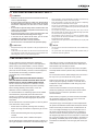
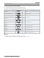
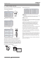
4.2 EFFICIENT USE OF COOLING AND HEATING
COOLING HEATING
1 Air ow direction: the appropriate air outlet angle is approx.
35º. If the cooling is not sufcient, change the air ow
direction. Pay attention to dew drop which may occur due to
the long cooling operation with low louvre angle.
35°
35°
Louver
angle
Air outlet angle (above center)
2 Air ow volume: ”AUTO” should be usually used.
3 Temperature: the recommended set temperature is 27 to 29ºC.
If the cooling is not sufcient, set the lower temperature.
1 Air ow direction: the appropriate air outlet angle is approx.
60º. If the heating is not sufcient, change the air ow
direction.
60° 60°
Louver
angle
Air outlet angle (above center)
2 Air ow volume: ”AUTO” should be usually used.
3 Temperature: the recommended set temperature is 18 to 20ºC.
If the heating is not sufcient, set the higher temperature.
? NOTE
About Multi-Split system
When the number of indoor unit or the operating mode is changed, the air outlet temperature may be changed and the indoor temperature is changed.
In this case, set as follows.
• During cooling: lower slightly the temperature setting.
• During heating: raise slightly the temperature setting.
5 MAINTENANCE
! DANGER
• Turn OFF the power source before the maintenance work. If not,
it may cause a re or an electric shock.
• Perform the maintenance work with stable footing. If not, it may
cause falling or injury.
! CAUTION
Hold the air lter and the air inlet grille securely by hand when opening,
closing, attaching or removing them. If not, it may cause the product
falling, resulting in an injury.
? NOTE
Do not operate the system without the air lter, to prevent the indoor unit
heat exchanger from being clogged.
5.1 DAILY MAINTENANCE
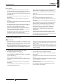
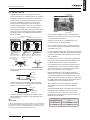
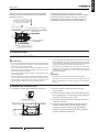
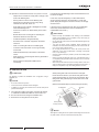
5.1.1 Cleaning Air Filter
1 Open the air inlet grille.
While sliding the knobs on both side of the air inlet grille in
the arrow direction, open the air inlet grille.
Air inlet grille
Knobs
2 Remove the air lter.
Hold the lower side of the air inlet grille and release the lter
lock. While sliding the air lter in the arrow direction, release
4 catches on both sides to remove the air lter from the air
inlet grille.
Upper Part of Filter
Hook
Hook
Lower Part of Filter
Air Filter
A
ir Inlet Grille
Air lter
Air inlet grille
Lower part of lter
Hook
Hook
Upper part of lter
3 Clean the air lter.
• Vacuum dust with a cleaner, or wash the air lter with water
or neutral detergent.
• Dry the air lter in the shade.
MAINTENANCE
PMML0477 rev.0 - 07/2017
4

ENGLISH
? NOTE
• Do not use hot water more than 50ºC. The air lter may be deformed
by heat.
• Do not dry the air lter with an open re, a dryer or a heater. The air
lter may be deformed.
4 Attach the air lter.
After the air lter is dried, attach it correctly to the air inlet
grille.
5 Close the air inlet grille.
? NOTE
• Be sure to attach the air lter. If the indoor unit is operated without the
air lter, it may cause malfunction of the indoor unit.
• Make sure that the air inlet grille is securely locked with the knobs. If
it is not properly locked, it might open suddenly, resulting in the grille
falling.
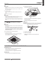
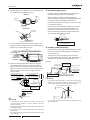
5.1.2 Removing, attaching and cleaning air
inlet grille
? NOTE
• Wipe the air inlet grille with a soft cloth soaked in lukewarm water
and squeezed.
• Use a soft cloth to clean the air inlet grille and the air panel. If
benzine, thinner or detergent (with surfactant) is used to cleaning, the
resin part may get discoloured or deformed. In addition, note that the
parts around the air outlet (louvre, guide, etc.) may be damaged if an
excessive force is applied.
The air inlet grille can be removed and cleaned.
1 Open the air inlet grille.
While sliding the knobs on both side of the air inlet grille in
the arrow direction, open the air inlet grille.
Knobs
Air inlet grille
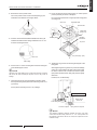
2 Remove the air inlet grille.
• Remove the supporting string from the air panel.
Supporting String
Supporting
string
• Open the air inlet grille at an approximately 45° angle from
the air panel surface.
• Tilting the air inlet grille, lift it up to remove it.
? NOTE
Although the air inlet grille can be opened up to 90°, it cannot be removed
from the air panel at the angle. Tilt it at a 45° angle when removing it.
45
o
Air panel
Ceiling
Tilting the air inlet grille, lift it up to remove it
3 Clean the air inlet grille.
4 Attach the air inlet grille.
Attach the air inlet grille in the reverse procedure to
removing.
5.2 MAINTENANCE AT BEGINNING AND END OF USE
At beginning of use
• Remove obstacles around the air inlet grilles and the air
outlet of the indoor unit and outdoor unit.
• Check that the air lter is not clogged with dust and dirt.
At end of use
• Clean the air lter, the air inlet grille and the air panel.
MAINTENANCE
PMML0477 rev.0 - 07/2017
5

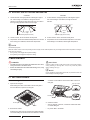
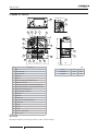
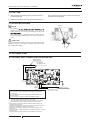
6 NAME OF PARTS
10
8
9
7
14
5
4
3
13
12
11
2
1
620
30 285
620
17
6
16 15 19 18
20
A
Human Detection Sensor
21
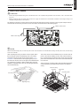
Internal gure of A
Nº Part Name
1 Fan
2 Fan motor (DC)
3 Heat exchanger
4 Distributor
5 Strainer
6 Micro-Computer control expansion valve
7 Electrical control box
8 Refrigerant gas pipe connection (with Øa are nut)
9 Refrigerant liquid pipe connection (with Øb are nut)
10 Drain pipe connection (VP25)
11 Drain discharge mechanism
12 Float switch
13 Drain pan
14 Rubber plug
15 Air panel: P-AP56NAMS (Optional)
16 Air inlet grille
17 Air lter
18 Air outlet
19 Air inlet
20 Cover for corner pocket
21 Motion sensor
(mm)
Model a b
RAI-50PPD 12,7 6,35
RAI-60PPD 12,7 6,35
? NOTE
Regarding the refrigerant cycle drawings and diagrams, refer to Technical Catalogue.
NAME OF PARTS
PMML0477 rev.0 - 07/2017
6

ENGLISH
7 BEFORE INSTALLATION
7.1 TRANSPORTATION AND HANDLING
! CAUTION
• Do not put any material on the product.
• Do not step on the product.
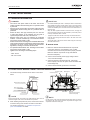
7.1.1 Transportation of indoor unit
• Transport the product as close to the installation location as
possible before unpacking.
• Do not put any material on the indoor unit.
• The indoor unit is packed upside down and therefore the
foamed polyethylene drain pan is exposed at the upper side.
Do NOT put the indoor unit with the drain pan side down
during the process from unpacking the indoor unit to hanging
up the unit to a ceiling. In addition, do NOT handle the indoor
unit by the drain pan portion or the air outlet portions.
• As foamed polyethylene is used for the indoor unit, take care
when handling the indoor unit. Applying an excessive force
to the unit may cause a breakage.
7.1.2 Handling of indoor unit
! DANGER
Do not put any foreign material into the indoor unit and check to
ensure that no foreign material exists in the indoor unit before
installation and the test run. Otherwise, a re or failure, etc. may
occur.
! CAUTION
• Do not hold the resin covers when holding or lifting the indoor unit.
• To avoid damage to the resin covers, put a cloth on them before lifting
or moving the indoor unit.
? NOTE
When lifting or moving the indoor unit, use appropriate slings to avoid
damage and be careful not to damage the insulation material on units
surface.
8 INDOOR UNIT INSTALLATION
! DANGER
• Do not install the indoor units outdoors. If installed outdoors, an
electric hazard or electric leakage will occur.
• Consider the air distribution from each indoor unit to the space
of the room, and select a suitable location so that uniform air
temperature in the room can be obtained.
• Avoid obstacles which may hamper the air intake or the air
discharge ow.
• Pay attention to the following points when the indoor units are
installed in a hospital or other places where there are electronic
waves from medical equipment, etc.:
- Do not install the indoor units where electromagnetic wave is
directly radiated to the electrical box, remote control cable
or remote control switch.
- Prepare a steel box and install the remote control switch in
it. Prepare a steel conduit tube and wire the remote control
cable in it. Then connect the ground wire with the box and
tube.
- Install a noise lter when the power supply emits harmful
noises.
- Do not install the indoor units, outdoor unit, remote control
switch and cable within approximately 3 meters of strong
electromagnetic wave radiators such as medical equipment.
• This unit is exclusive non electrical heater type indoor unit. It is
prohibited to install an electrical heater in the eld.
• Do not put any foreign material into the indoor unit and check to
ensure that none exist in the indoor unit before the installation
and test running. Otherwise a re or failure, etc., may occur.
• Do not perform installation work, refrigerant piping work, drain
pumping, drain piping and electrical wiring connecting work
without referring to the installation manual. If the instructions
are not followed, it may result in a water leakage, an electric
shock, a re and an injury.
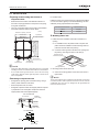
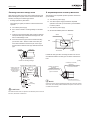
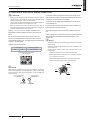
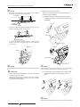
• Mount suspension bolts using M10 (W3/8) as size, as shown
below:
I-Beam
Suspension bolts
(W3/8 or M10)
For concrete slab
150~160mm
Steel
Anchor bolt
Wooden beam
Concrete
Wooden bar
(60mm to 90mm square)
Nuts
Sling bolt
(W3/8 or M10)
Square
washers
! CAUTION
• Do not install the indoor units in a ammable environment to avoid a
re or an explosion.
• Check to ensure that the ceiling slab is strong enough. If not strong
enough, the indoor unit may fall down on you.
• Do not install the indoor units in a machinery shop or kitchen where
vapour from oil or mist ows to the indoor units. The oil will deposit
on the heat exchanger, thereby reducing the indoor unit performance,
and may deform. In the worst case, the oil damages the plastic parts
of the indoor unit.
• To avoid any corrosive action to the heat exchangers, do not install
the indoor units in an acid or alkaline environment.
• When lifting or moving the indoor unit, use appropriate slings to avoid
damage and be careful not to damage the insulation material on units
surface.
BEFORE INSTALLATION
PMML0477 rev.0 - 07/2017
7

8.1 FACTORY-SUPPLIED ACCESSORIES
Check to ensure that the following accessories are packed with the indoor unit.
The hose band, screws, washers and plastic bands are put in the pipe insulation.
Accessory Qty. Purpose
Checking scale
(cut and take out it from the carton board)
Accessory
Q'ty
Purpose
Checking Scale
(Cut and Take Out it
from the Carton Board)
Cross Recessed
Head Screws (M5)
Washer with Insulation
Material (M10)
Washer (M10)
Drain Hose
Hose Clamp
Pipe Insulation
Pipe Insulation
Cord Clamp
Cord Clamp
Insulation
(5Tx50x200)
Insulation
(5Tx100x200)
4
4
4
2
6
1
1
1
1
1
1
Insulation
(5Tx25x500)
1
1
For Adjusting Space of False
Ceiling Opening and
Position of the Unit
For Fitting Paper Pattern
For Unit Installation
For Refrigerant Piping
Connection
For Drain Hose Connection
For Fixing Remote Control
Switch Wiring, Louver Sensor
and Insulation of Piping
For Covering Drain
Connection
For Covering Wiring
Connection
For Covering Drain
Connection
1
For adjusting space of false ceiling opening and position of
the unit
Cross recessed head screws (M5)
Accessory
Q'ty
Purpose
Checking Scale
(Cut and Take Out it
from the Carton Board)
Cross Recessed
Head Screws (M5)
Washer with Insulation
Material (M10)
Washer (M10)
Drain Hose
Hose Clamp
Pipe Insulation
Pipe Insulation
Cord Clamp
Cord Clamp
Insulation
(5Tx50x200)
Insulation
(5Tx100x200)
4
4
4
2
6
1
1
1
1
1
1
Insulation
(5Tx25x500)
1
1
For Adjusting Space of False
Ceiling Opening and
Position of the Unit
For Fitting Paper Pattern
For Unit Installation
For Refrigerant Piping
Connection
For Drain Hose Connection
For Fixing Remote Control
Switch Wiring, Louver Sensor
and Insulation of Piping
For Covering Drain
Connection
For Covering Wiring
Connection
For Covering Drain
Connection
4 For tting paper pattern
Washer with insulation material (M10)
Accessory
Q'ty
Purpose
Checking Scale
(Cut and Take Out it
from the Carton Board)
Cross Recessed
Head Screws (M5)
Washer with Insulation
Material (M10)
Washer (M10)
Drain Hose
Hose Clamp
Pipe Insulation
Pipe Insulation
Cord Clamp
Cord Clamp
Insulation
(5Tx50x200)
Insulation
(5Tx100x200)
4
4
4
2
6
1
1
1
1
1
1
Insulation
(5Tx25x500)
1
1
For Adjusting Space of False
Ceiling Opening and
Position of the Unit
For Fitting Paper Pattern
For Unit Installation
For Refrigerant Piping
Connection
For Drain Hose Connection
For Fixing Remote Control
Switch Wiring, Louver Sensor
and Insulation of Piping
For Covering Drain
Connection
For Covering Wiring
Connection
For Covering Drain
Connection
4
For unit installation
Washer (M10)
Accessory
Q'ty
Purpose
Checking Scale
(Cut and Take Out it
from the Carton Board)
Cross Recessed
Head Screws (M5)
Washer with Insulation
Material (M10)
Washer (M10)
Drain Hose
Hose Clamp
Pipe Insulation
Pipe Insulation
Cord Clamp
Cord Clamp
Insulation
(5Tx50x200)
Insulation
(5Tx100x200)
4
4
4
2
6
1
1
1
1
1
1
Insulation
(5Tx25x500)
1
1
For Adjusting Space of False
Ceiling Opening and
Position of the Unit
For Fitting Paper Pattern
For Unit Installation
For Refrigerant Piping
Connection
For Drain Hose Connection
For Fixing Remote Control
Switch Wiring, Louver Sensor
and Insulation of Piping
For Covering Drain
Connection
For Covering Wiring
Connection
For Covering Drain
Connection
4
Drain hose
Accessory
Q'ty
Purpose
Checking Scale
(Cut and Take Out it
from the Carton Board)
Cross Recessed
Head Screws (M5)
Washer with Insulation
Material (M10)
Washer (M10)
Drain Hose
Hose Clamp
Pipe Insulation
Pipe Insulation
Cord Clamp
Cord Clamp
Insulation
(5Tx50x200)
Insulation
(5Tx100x200)
4
4
4
2
6
1
1
1
1
1
1
Insulation
(5Tx25x500)
1
1
For Adjusting Space of False
Ceiling Opening and
Position of the Unit
For Fitting Paper Pattern
For Unit Installation
For Refrigerant Piping
Connection
For Drain Hose Connection
For Fixing Remote Control
Switch Wiring, Louver Sensor
and Insulation of Piping
For Covering Drain
Connection
For Covering Wiring
Connection
For Covering Drain
Connection
1
For drain hose connection
Hose clamp
Accessory
Q'ty
Purpose
Checking Scale
(Cut and Take Out it
from the Carton Board)
Cross Recessed
Head Screws (M5)
Washer with Insulation
Material (M10)
Washer (M10)
Drain Hose
Hose Clamp
Pipe Insulation
Pipe Insulation
Cord Clamp
Cord Clamp
Insulation
(5Tx50x200)
Insulation
(5Tx100x200)
4
4
4
2
6
1
1
1
1
1
1
Insulation
(5Tx25x500)
1
1
For Adjusting Space of False
Ceiling Opening and
Position of the Unit
For Fitting Paper Pattern
For Unit Installation
For Refrigerant Piping
Connection
For Drain Hose Connection
For Fixing Remote Control
Switch Wiring, Louver Sensor
and Insulation of Piping
For Covering Drain
Connection
For Covering Wiring
Connection
For Covering Drain
Connection
1
Insulation
(5Tx50x200)
Accessory
Q'ty
Purpose
Checking Scale
(Cut and Take Out it
from the Carton Board)
Cross Recessed
Head Screws (M5)
Washer with Insulation
Material (M10)
Washer (M10)
Drain Hose
Hose Clamp
Pipe Insulation
Pipe Insulation
Cord Clamp
Cord Clamp
Insulation
(5Tx50x200)
Insulation
(5Tx100x200)
4
4
4
2
6
1
1
1
1
1
1
Insulation
(5Tx25x500)
1
1
For Adjusting Space of False
Ceiling Opening and
Position of the Unit
For Fitting Paper Pattern
For Unit Installation
For Refrigerant Piping
Connection
For Drain Hose Connection
For Fixing Remote Control
Switch Wiring, Louver Sensor
and Insulation of Piping
For Covering Drain
Connection
For Covering Wiring
Connection
For Covering Drain
Connection
1 For covering wiring connection
Insulation
(5Tx100x500)
Accessory
Q'ty
Purpose
Checking Scale
(Cut and Take Out it
from the Carton Board)
Cross Recessed
Head Screws (M5)
Washer with Insulation
Material (M10)
Washer (M10)
Drain Hose
Hose Clamp
Pipe Insulation
Pipe Insulation
Cord Clamp
Cord Clamp
Insulation
(5Tx50x200)
Insulation
(5Tx100x200)
4
4
4
2
6
1
1
1
1
1
1
Insulation
(5Tx25x500)
1
1
For Adjusting Space of False
Ceiling Opening and
Position of the Unit
For Fitting Paper Pattern
For Unit Installation
For Refrigerant Piping
Connection
For Drain Hose Connection
For Fixing Remote Control
Switch Wiring, Louver Sensor
and Insulation of Piping
For Covering Drain
Connection
For Covering Wiring
Connection
For Covering Drain
Connection
1 For covering drain connection
Insulation
(5Tx25x500)
Accessory
Q'ty
Purpose
Checking Scale
(Cut and Take Out it
from the Carton Board)
Cross Recessed
Head Screws (M5)
Washer with Insulation
Material (M10)
Washer (M10)
Drain Hose
Hose Clamp
Pipe Insulation
Pipe Insulation
Cord Clamp
Cord Clamp
Insulation
(5Tx50x200)
Insulation
(5Tx100x200)
4
4
4
2
6
1
1
1
1
1
1
Insulation
(5Tx25x500)
1
1
For Adjusting Space of False
Ceiling Opening and
Position of the Unit
For Fitting Paper Pattern
For Unit Installation
For Refrigerant Piping
Connection
For Drain Hose Connection
For Fixing Remote Control
Switch Wiring, Louver Sensor
and Insulation of Piping
For Covering Drain
Connection
For Covering Wiring
Connection
For Covering Drain
Connection
1 For covering drain connection
Flare nut 1 For refrigerant liquid pipe connection
? NOTE
• If any of these accessories are not packed with the unit, please contact your contractor.
• The air panel, remote control switch and branch pipes are optional accessories and so are not included.
INDOOR UNIT INSTALLATION
PMML0477 rev.0 - 07/2017
8

ENGLISH
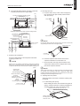
8.2 INITIAL CHECK
• Install the indoor unit with a proper clearance around it
paying careful attention of installation direction for the piping,
wiring and maintenance working space, as shown below.
• The electrical box is located to the side surface of the unit
body. When installing the indoor unit, set up a service
access door at the electrical box side for servicing. For
servicing of the electrical box, make sure not to install the
refrigerant and drain piping in front of the electrical box.
• When equipping the duct adapter (optional), setup a service
access door at the duct adapter side in order to install the
duct adapter. Refer to the installation manual of the duct
adapter for details.
Min.
1500
Min.
1500
Min.
1500
Min.
1500
Min.
1500
Min.
1500
Min.
1500
Min.
1500
Min.
1500
Min.
1500
Min.
3000
Min. 500 Min. 100
Min. 500
Min. 1000
Min. 100
Min.
2400
Distance from wall side
Service access door
Access door for duct adapter (optional)
Piping connection
Piping connection
Piping connection
Minimum service space
Piping connection side
Electrical box side
Electrical box
Service access door
Service access door
Electrical box
Electrical box
Access door for duct adapter (optional)
• Check space between ceiling and false ceiling is enough as
indicated below.
285mm
Clearance:
Min. 30 mm
Unit height in
false ceiling
• The drain piping shall be installed on a downward slope
of 1/25 to 1/100 as shown in the gure below. Refer to the
Chapter "10 Drain piping" for details.
Downward slope:
1/25 to 1/100
Drain piping
• Check that the ceiling surface is at and suitable for the air
panel installation. If the ceiling is not at, drain water could
not ow smoothly.
? NOTE
In the case installing the indoor unit to a grid ceiling, do not touch the unit
body, the electrical wiring and refrigerant piping to a suspension bolt of a
grid. Check the location of suspension bolts of a grid ceiling and indoor
unit mounting position before installing of the indoor unit.
Suspension bolt for
indoor unit
Suspension Bolt
for Indoor Unit
Suspension Bolt for
Grid Ceiling
Suspension Bolt for
Grid Ceiling
Grid Ceiling
Suspension bolt
for grid ceiling
Grid ceiling
• Select a suitable installation location, considering the air
distribution from each indoor unit to the whole room so that
room temperature will be uniform.
• Install the unit where there is no obstacles which may
hamper the suction air and discharged air.
• Do not install the unit near a door or a window where the
indoor unit may contact humid outside air. Otherwise, dew
condensation may occur.
• In case temperature and humidity inside the ceiling exceeds
30ºC/RH (Relative Humidity) 80%, apply additional insulation
materials to the external surface of the indoor unit to avoid
dew condensation.
• If installing the indoor unit to a high ceiling, the warmed air
may stay around the ceiling during heating operation. Thus,
the parallel installing of a circulator is recommended.
• Do not install the indoor unit where the airow from the air
outlet blows directly to the temperature detecting devices
such an alarm device or a control device. It may cause a
failure of an alarm device or a control device.
• Multiple Combinations. For simultaneous operation of
multiple units, the units must be installed in the same room
and be operated under the same conditions. If the room is
partitioned by a wall, furniture or a curtain, etc., it may cause
an operation failure. Take care when rearranging furniture or
remodelling the room after installation as well.
• When installing the receiver kit (optional) or the motion
sensor (optional), refer to their respective Installation
manuals.
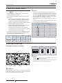
• "STATIC PRESSURE SW" on the PCB must be set to HIGH
PRESSURE when installing the indoor unit at a height
of more than 2500 mm from the oor. It must be set to
NORMAL when installing the indoor unit at a height of less
than 2500 mm from the oor.
Ceiling height
STATIC PRESSURE SW
SW504
RAI-(50/60)PPD
≤ 2.5 m NORMAL
≤ 3.5 m HIGH
INDOOR UNIT INSTALLATION
PMML0477 rev.0 - 07/2017
9

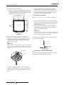
8.3 INSTALLATION
Opening of false ceiling and location of
suspension bolts
• Determine the nal location and installation direction of
the indoor unit paying attention to the space for the piping,
wiring and maintenance.
• Then cut out the false ceiling for the indoor unit installation
and install suspension bolts, as shown below:
(mm)
Unit size: 570
Dimension of
suspension bolts: 530
4-positions of
suspension bolts
Dimension of opening: 576~590
Piping
connection side
Drain piping
connection side
Optional panel
Unit size: 570
Dimension of
suspension bolts: 530
Dimension of opening: 576~590
? NOTE
• Ceiling work differs depending on the building structure. Consult with
a building constructor or an interior nish worker for more information.
• Do not install electric light and the indoor unit to the same furring
of the ceiling. Otherwise, electric lights may icker or vibrate due to
indoor unit operation.
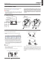
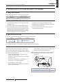
Mounting of suspension bolts
• Strengthen the opening parts of the false ceiling. Using a
steel C-prole makes the work easier.
• Mount suspension bolts, as shown.
• Strengthen suspension bolts with support plates as required
in preparation for an earthquake. Suspension bolts and
support plates shall be M10 (eld-supplied).
For concrete slab:
150 to 160mm
Insert
(100 to 150kg)
Steel
Concrete
Anchor Bolt
(W3/8 or M10)
Anchor bolt
(W3/8 or M10)
Concrete
Steel
150 to 160mm
Insert
(100 to 150kg)
For steel beam:
I-Beam
Suspension bolt
(W3/8 or M10)
For wooden beam:
Install the indoor unit to the tie beam (for single-storied building)
or to the second oor girder (for two-storied building), and use
sufciently strong squared timber shown below.
Interval between beams Squared timber
< 90 cm 6 square
< 180 cm 9 square
Mounting indoor unit
1 Pattern board for installation and scale for dimension of
opening
a. For installation work, the pattern board is required. The
pattern board for installation and the checking scale are
printed on the back side of the packing.
b. Cut off the checking scale for dimension of opening from
the packing. The usage is shown in the item (5).
Checking scale for
dimension of opening
Packing
(Corrugated board)
Pattern board for
installation
2 Mounting position of the indoor unit
a. Check the mounting position of the indoor unit shown in
gure below:
? NOTE
The air panel (optional) may be deformed if the levelness of the indoor
unit and the position of the suspension brackets are incorrect, and dew
condensation may occur due to air leakage from the gap between the
indoor unit and the air panel.
INDOOR UNIT INSTALLATION
PMML0477 rev.0 - 07/2017
10

ENGLISH
b. The positional relation between the indoor unit and the
air panel (optional) is shown in gure below:
285
90
30
*16
Min.30
Surface of ceiling
Washer
(accessory)
Double nut
(eld-supplied)
4-positions of suspension bolts (M10 or W3/8)
(eld-supplied)
(mm)
* Dimension between bottom side of unit and ceiling surface
177
140
180
145
94
521
Wiring connection
Drain pipe
connection
Refrigerant liquid pipe
connection
Refrigerant gas pipe
connection
(Drain pipe)
(Drain pipe)
(Gas pipe)
(Liquid pipe)
(Gas pipe)
(Liquid pipe)
3 Mounting nuts and washers
Screw nuts and washers on the suspension bolts before
mounting the indoor unit.
? NOTE
Make sure to use washers (accessories) for xing the suspension
bolts to the suspension brackets. The washer with insulation must
be tted with the insulation side downward to facilitate hanging work.
90
(mm)
Nut (eld-supplied)
Suspension bolt
(eld-supplied)
Washer with insulation
(accessory)
Approx
45
Surface of ceiling
Suspension bracket
(attached indoor unit)
Washer
(accessory)
Nut (eld-supplied)
Approx
50
4 Mounting indoor unit
a. Lift up the indoor unit by a hoist, and do not apply any
force to the drain pan (the air outlet portions and the
drain pan portion).
Suspension
Bolt
Suspension
Bracket
Drain Pan
Drain pan
Suspension bolt
Suspension bracket
? NOTE
For the grid ceiling, incline the unit and then mount the unit from the
refrigerant pipe side as shown in the gure below.
Refrigerant pipe side
Grid ceiling
b. Insert the suspension bolts into the notches of the
suspension brackets to hook the indoor unit.
c. Secure the indoor unit using nuts and washers. Then
check that the washers serve as stoppers at the rising
parts of the suspension brackets.
? NOTE
After hooking up the indoor unit, piping and wiring work inside the ceiling
are required. Thus, especially if the false ceiling has already been
installed, determine the pipe direction and complete the rest of the piping
and wiring work before hooking the indoor unit.
5 Adjusting indoor unit position
Adjust the position of the indoor unit with the checking scale
as required.
a. For false ceiling with opening.
When installing the indoor unit to the false ceiling with an
opening, check the dimension of opening and adjust the
clearance between the indoor unit and the opening.
Attach the scale to the bottom side of the unit.
Attach the scale to the face of ceiling.
A
djust the height of
the ceiling and the unit
at each corner
.
Adjust the height of
the ceiling and the
unit at each corner.
Attach the scale to the face of ceiling
Attach the scale to the bottom side of the unit
INDOOR UNIT INSTALLATION
PMML0477 rev.0 - 07/2017
11

b. For false ceiling without opening
If there is no opening in the existing false ceiling, provide
an opening in it before mounting the indoor unit. Cut out
the false ceiling. After hooking up the indoor unit, adjust
the position according to the procedure (a).
5
5
5
576~590
576~590
570
570
5
Dimension of opening
Indoor unit
Surface
of ange
Dimension of opening
Electrical box
6 Tighten two nuts of each suspension bolt after the
adjustment is completed. Apply LOCK-TIGHT paint to the
suspension bolts and nuts in order to prevent them from
loosening. Adjust the indoor unit to the correct position,
using the checking scale.
? NOTE
While adjusting the space between the indoor unit and the ceiling
surface, keep the indoor unit level. Otherwise, it may cause a
malfunction of the oat switch. Check the levelness of the unit with
a level.
Level
Vinyl tube
Drain pipe
Corrugated board
Check the levelness at each corner (•) of the unit with a
level or by pouring water to the clear vinyl tube as shown in
the gure. Make the corner at the drain pipe side 1 to 3mm
lower.
7 The upper surface of the unit is protected by corrugated
cardboard to prevent the unit from being damaged by
spatter, etc. When mounting the air panel (optional), check
to ensure that welding around the unit has been nished
before removing the corrugated cardboard.
Installation of air panel
Refer to "12 Installation of optional air panel: P-AP56NAMS".
1 Check the distance between the indoor unit and the false
ceiling. It is 16
+3
0
mm as shown in the gure. If not, adjust the
distance by using the checking scale with maintaining the
levelness of the indoor unit.
2 Check that the xing screws for the panel are tightened.
Tighten the xing screws for the panel until touching the
stopper to the suspension bracket.
? NOTE
Pay attention to the distance between the indoor unit and the false
ceiling. If it is 19mm or more, it may cause dew condensation by
leaking air from the seal packing (Field-Supplied).
3 Check the indoor unit height from the false ceiling surface.
For air panel P-AP56NAMS
3
Indoor unit
Ceiling surface
Installation of remote control switch
For details on installation of the remote control switch, refer to
Installation and Operation Manual of the product.
INDOOR UNIT INSTALLATION
PMML0477 rev.0 - 07/2017
12
La pagina si sta caricando...
La pagina si sta caricando...
La pagina si sta caricando...
La pagina si sta caricando...
La pagina si sta caricando...
La pagina si sta caricando...
La pagina si sta caricando...
La pagina si sta caricando...
La pagina si sta caricando...
La pagina si sta caricando...
La pagina si sta caricando...
La pagina si sta caricando...
La pagina si sta caricando...
La pagina si sta caricando...
-
 1
1
-
 2
2
-
 3
3
-
 4
4
-
 5
5
-
 6
6
-
 7
7
-
 8
8
-
 9
9
-
 10
10
-
 11
11
-
 12
12
-
 13
13
-
 14
14
-
 15
15
-
 16
16
-
 17
17
-
 18
18
-
 19
19
-
 20
20
-
 21
21
-
 22
22
-
 23
23
-
 24
24
-
 25
25
-
 26
26
-
 27
27
-
 28
28
-
 29
29
-
 30
30
-
 31
31
-
 32
32
-
 33
33
-
 34
34


Hitachi RAI-50PPD Istruzioni per l'uso
- Categoria
- Condizionatori d'aria a sistema split
- Tipo
- Istruzioni per l'uso
- Questo manuale è adatto anche per
in altre lingue
Documenti correlati
-
Hitachi P-N23NA2, P-AP160KA3, P-AP160NAE2 Air Panel Cooling and Heating Manuale utente
-
Hitachi RAC-VJ18PHAE Manuale utente
-
-
-
-
-
Hitachi RAC Series Manuale utente
-
-
-
Altri documenti
-
LG CV18 Manuale utente
-
LG UV12H.NJ1 Manuale utente
-
Electrolux EXC650EIWA24 Guida d'installazione
-
Sanyo 36XH72R Manuale utente
-
Mitsubishi Electric PXZ-4F75VG Split-Type Air-Conditioner Manuale utente
-
Haier AC18CS1ERA Istruzioni per l'uso
-
McQuay M5WMY15KR Guida d'installazione
-
LG UV42R.N20 Guida d'installazione
-
-