KTM 60712929100 Manuale del proprietario
- Tipo
- Manuale del proprietario

TOURING TOP CASE
INFORMATION
KTM Sportmotorcycle GmbH
5230 Mattighofen, Austria
www.ktm.com
60712929000
06.2018
3.213.620
*3213620*

2
Le agradecemos que se haya decidido por este producto.
Este producto de alta calidad está probado para la competición y se ha desarrollado especíğ camente para las exigencias de este deporte. Para poder garantizar
los máximos niveles de seguridad y funcionalidad, es imprescindible que el producto se monte correctamente. Por este motivo, es muy importante que siga las
instrucciones del manual de montaje o que se ponga en contacto con su concesionario autorizado.
El (cuasi) fabricante y el proveedor de este producto no se harán responsables del montaje y el uso incorrectos.
¡Muchas gracias!
Wir freuen uns, dass Sie sich für dieses Produkt entschieden haben.
Unser hochwertiges Qualitätsprodukt ist rennerprobt und wurde speziell für sportliche Herausforderungen entwickelt. Eine korrekte Montage des Produktes
ist unerlässlich, um ein Maximum an Sicherheit und Funktionalität gewährleisten zu können. Bitte befolgen Sie daher die Montageanleitung oder wenden Sie
sich an Ihren autorisierten Fachhändler.
Für falsche Montage oder Verwendung dieses Produktes kann der (Quasi-)Hersteller bzw. Lieferant nicht zur Verantwortung gezogen werden.
Vielen Dank.
Thank you for choosing this product.
Our high quality product has been tested under racing conditions and was developed speciğ cally for use in sports activities. Correct installation of the product
is essential to ensure that a maximum degree of safety and functionality is achieved. Therefore, please follow the installation instructions or contact your
authorized dealer.
The (quasi) manufacturer or supplier cannot be held responsible for products that are incorrectly mounted or inappropriately used.
Thank you.
Grazie per aver scelto questo prodotto.
Questo nostro prodotto di pregiata qualità è collaudato nelle competizioni ed è stato sviluppato speciğ camente per gare sportive. Il montaggio corretto del prodotto
è fondamentale per garantirne la massima sicurezza e funzionalità. Rispetti quindi le istruzioni di montaggio o rivolgersi al proprio concessionario autorizzato.
Il produttore (detentore del marchio)/fornitore non può essere considerato responsabile per un montaggio o impiego errato del presente prodotto.
Vi ringraziamo per l’attenzione!
Merci d‘avoir porté votre choix sur ce produit.
Notre produit de haute qualité est éprouvé pour les compétitions et a été conçu spécialement pour un usage sportif. Un montage approprié du produit est
indispensable pour garantir une sécurité et une fonctionnalité maximales du véhicule. C‘est pourquoi nous vous invitons à suivre scrupuleusement le manuel
de montage ou à vous adresser à votre revendeur agréé.
En cas de montage ou d‘utilisation non conformes de ce produit, le (quasi) constructeur ou le fournisseur déclinent toute responsabilité.
Merci !
19 ITALIANO
27 FRANÇAIS
35 ESPAÑOL
3 DEUTSCH
11 ENGLISH

3
DEUTSCH
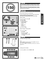
Lieferumfang
1x Top Case (36 Liter Volumen)
1x Gleitplatte
4x Montagekit
4x Bundschraube M8x35
4x Gleitbuchse
4x Gummischeibe
4x Beilagscheibe
4x Gleitführung
4x Distanzbuchse
4x Gummilager
1x Schließzylinder
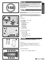
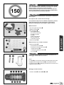
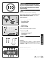
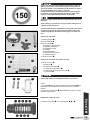
Bei angebautem Top Case kann es, insbesondere in beladenem
Zustand, wegen größerer Seitenwindempfi ndlichkeit zu verän-
dertem Fahrverhalten, aber auch zu verändertem Kurven- und
Bremsverhalten kommen!
Vorsicht bei starken Winden! Aufgrund des geänderten Fahrver-
haltens langsam an die zulässige Höchstgeschwindigkeit von 150
km/h herantasten!
Die Ladung gleichmäßig verteilen und gegen Verrutschen sichern!
Achten Sie stets darauf, dass die Zuladung von 5 kg keinesfalls
überschritten wird!
Für das Reinigen des Top Cases keinen Hochdruckreiniger ver-
wenden, da der hohe Druck die Dichtung beschädigen kann.
Benutzen Sie ein neutrales Reinigungsmittel (Wasser mit Neutral-
seife)!
Lieferumfang Schließzylinder
1x Schließzylinder
12x Zuhaltung
15x Feder für Zuhaltung
2x Einrastblech
1x Feder für Einrastblech
1x O-Ring
Der Kit enthält viele Kleinteile. Es wird empfohlen den Zusam-
menbau an einem Tisch sitzend durchzuführen!
HINWEIS
Die Federn für die Zuhaltungen unterscheiden sich durch die
geringere Federrate von der Feder für das Einrastblech.
Das Einrastblech ist daran zu erkennen, dass keine Ziffer einge-
prägt ist.
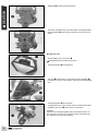
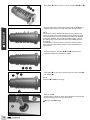
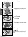
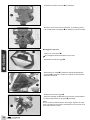
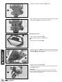
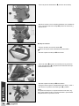
Montage Schließzylinder
- Federn in die Kammern , und einsetzen.

4
DEUTSCH
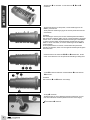
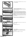
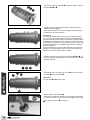
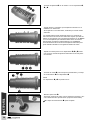
- Zuhaltungen mit der Ziffer 1 in die Kammern , und
einsetzen.
- Schlüssel einsetzen und überprüfen, ob die Zuhaltungen mit der
Ziffer 1 passend sind.
- Nicht passende Zuhaltungen gegen die mit der passenden Nummer
austauschen.
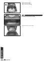
HINWEIS
Die Zuhaltungen müssen plan mit dem Schließzylinder abschließen.
Die Anzahl der sichtbaren Rillen zeigt an, welche Zuhaltung verwendet
werden muss. In diesem Beispiel sind drei Zuhaltungen mit der Ziffer
1 verbaut. Bei den beiden herausstehenden Zuhaltungen sind zwei
Rillen zu sehen. Das heißt, es müssen Zuhaltungen mit der Ziffer 3
verbaut werden.
Es ist empfehlenswert zu notieren, welche Ziffern die passenden
Zuhaltungen besitzen, damit man die folgenden Schließzylinder gleich
bestücken kann.
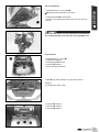
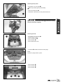
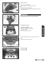
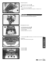
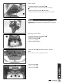
- Arbeitsschritte für die Kammern , und wiederholen, bis die
ersten sechs Kammern mit den passenden Zuhaltungen belegt sind.
- Feder für das Einrastblech und Einrastblech in die Kammer
einsetzen.
HINWEIS
Die Kammern und werden nicht belegt.
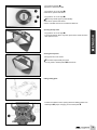
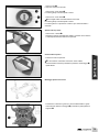
- O-Ring montieren.
- Schließzylinder wie in der Abbildung gezeigt positionieren und mit
Hilfe des Schlüssels einsetzen (Nase muss nach unten zeigen).
Einrastblech rastet ein.

5
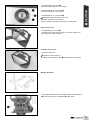
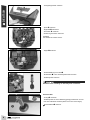
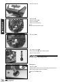
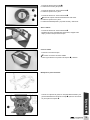
Öffnen des Top Case
- Schlüsselstellung 90° rechts .
- Druckknopf ganz nach hinten schieben, nach unten drücken und
gleichzeitig den Deckel aufziehen.
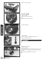
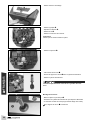
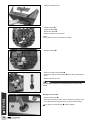
Montage Gleitplatte
- Gummilager, Distanzbuchsen und Gleitführungen des Montagekits
(Lieferumfang) auf der Trägerplatte (1 positionieren.
- Schlüsselstellung nach oben :
Top Case ist abgeschlossen und verriegelt.
- Schlüsselstellung 90° nach rechts :
Koffer lässt sich öffnen und schließen.
- Schlüsselstellung 45° nach rechts :
Tragegriff springt automatisch nach oben.
Koffer lässt sich öffnen und schließen.
Koffer ist entriegelt und lässt sich montieren und abnehmen.
Schließen des Top Case
- Deckel fest zudrücken.
Verschluss rastet hörbar ein.
- Schlüssel auf verriegelte Position zurück drehen und abziehen.
DEUTSCH

6
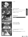
- Gleitplatte (Lieferumfang) positionieren.
- Schrauben mit Gleitbuchsen, Gummischeiben und Beilagscheiben
des Montagekits (Lieferumfang) montieren und mit 25 Nm fest-
ziehen.
- Top Case (Lieferumfang) in den Führungen der Gleitplatte
positionieren und nach vorn schieben, bis es fest auf der Gleitplatte
sitzt.
- Verriegelungshebel (2 einschwenken.
- Tragegriff ganz nach unten drücken und den Schlüssel auf Schlüs-
selstellung nach oben zurück drehen und abziehen.
HINWEIS
Sollte sich der Verriegelungshebel nicht einschwenken lassen, ist
das Top Case noch nicht in der richtigen Position eingerastet oder
der Schlüssel nicht in korrekter Stellung.
Montage Top Case
- Schlüsselstellung 45° nach rechts .
Tragegriff springt automatisch nach oben.
- Verriegelungshebel (2 ausschwenken.
DEUTSCH

7
Top Case abnehmen
- Schlüsselstellung 45° nach rechts .
Tragegriff springt automatisch nach oben.
- Verriegelungshebel (2 ausschwenken.
- Top Case am Tragegriff nach hinten ziehen und nach oben ab-
nehmen.
Achten Sie stets darauf, dass alle Zubehörteile und Gepäckstü-
cke sorgfältig befestigt sind. Prüfen Sie dies regelmäßig nach!
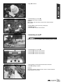
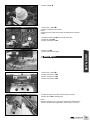
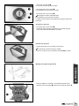
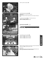
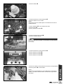
Schlossausbau
- Schlüsselstellung 90° rechts .
- Fangbänder aushängen.
- Gummidichtung (3 entfernen.
- Schrauben (4 entfernen.
- Rahmen mit Deckel entfernen.
- Hebel (5 nach außen schieben und mit Feder entfernen.
HINWEIS
Auf Verbleib der Federn achten.
- Schrauben (6 entfernen.
- Schrauben (7 entfernen.
- Schrauben (8 entfernen.
DEUTSCH

8
- Schlüsselstellung nach oben .
- Einrastblech in den Schließzylinder hinein drücken.
- Schließzylinder entfernen.
Schlüssel muss unbedingt im Schließzylinder verbleiben!
- Kappe )2 entfernen.
Schlosseinbau
- O-Ring montieren.
- Schließzylinder wie in der Abbildung gezeigt positionieren und mit
Hilfe des Schlüssels einsetzen (Nase muss nach unten zeigen).
Einrastblech rastet ein.
- Verriegelungseinheit entfernen.
- Splint (9 entfernen.
- Kipphebel (: abnehmen.
- Schrauben )1 entfernen.
- Abdeckung mit Federn entfernen.
HINWEIS
Auf Verbleib der Federn achten.
DEUTSCH

9
- Kappe )2 montieren.
- Schlüsselstellung 90° rechts .
- Abdeckung mit Federn montieren.
HINWEIS
Sicher stellen, dass die Federn richtig auf den entsprechenden
Nasen sitzen.
- Kipphebel (: mit Feder nach oben positionieren.
- Splint (9 montieren.
- Schrauben )1 montieren und festziehen.
- Schlüsselstellung nach oben .
- Verriegelungseinheit montieren.
Die Feder muss auf der entsprechenden Vertiefung sitzen (s. Pfeil)!
- Schlüsselstellung 90° rechts .
- Schrauben (6 montieren und festziehen.
- Schrauben (7 montieren und festziehen.
- Schrauben (8 montieren und festziehen.
- Feder beidseitig auf der entsprechenden Nase montieren.
- Hebel (5 beidseitig montieren.
HINWEIS
Auf richtigen Sitz der Hebel und Federn achten und das alle Nasen
richtig eingehakt sind (s.Pfeil).
DEUTSCH

10
- Rahmen mit Deckel montieren.
- Gummidichtung (3 montieren.
- Schrauben (4 montieren und festziehen.
- Fangbänder einhängen und Deckel schließen.
Den Stoß der Gummidichtung auf der gegenüberliegenden Sei-
te des Schlosses ansetzen, damit aus der Öffnung das Wasser
ablaufen kann!
DEUTSCH

11
When the Top Case is mounted, especially when it is loaded,
greater side wind susceptibility will cause a change in vehicle
handling characteristics while riding, taking curves, and brak-
ing!
Exercise caution in high winds! Due to the changes in vehicle
handling characteristics, accelerate gradually to the permitted
maximum speed of 150 km/h!
Distribute the load evenly and secure it well to prevent slipping!
Ensure that the load never exceeds 5 kg!
Do not use a high-pressure cleaner to clean the Top Case as
the high pressure may damage the seals!
Use a neutral cleaning agent (water with neutral soap)!
Scope of supply
1x Top Case (36 liter capacity)
1x sliding plate
4x assembly kit
4x collar screw M8x35
4x sliding bushing
4x rubber washer
4x shims
4x sliding guide
4x spacer
4x rubber mount
1x locking cylinder
Scope of supply: locking cylinder
1x locking cylinder
12x wafer
15x spring for wafer
2x snap-in plate
1x spring for snap-in plate
1x O-ring
This kit contains many small parts. It is advisable to carry out
assembly while sitting at a table!
NOTE
The springs for the wafers differ from spring for the snap-in
plate in terms of the lower spring rate.
The snap-in plate can be identifi ed by the fact that no number is
stamped on it.
Locking cylinder assembly
- Insert springs into chambers , and .
ENGLISH

12
- Insert wafers with the number 1 into the chambers , and .
- Insert the key and check whether the wafers with the number 1 fi t.
- Replace wafers that do not fi t with wafers with the right number.
NOTE
The wafers should be aligned fl ush with the locking cylinder. The
number of visible grooves indicates which wafer needs to be used.
This example shows a cylinder in which three wafers with number
1 have been installed. Two grooves are visible on each of the two
protruding wafers. This means that wafers with number 3 need to
be installed.
It is advisable to note down which numbers the matching wafers
have so that the other locking cylinders can be assembled in the
same manner.
- Repeat the steps for chambers , and until the fi rst six
chambers are fi lled with the matching wafers.
- Insert spring for the snap-in plate and then the snap-in plate
into chamber .
NOTE
Chambers and remain empty.
- Mount O-ring .
- Position locking cylinder as shown in the illustration and insert with
the aid of the key (catch must face downward).
Snap-in plate engages.
ENGLISH

13
Opening the Top Case
- Key position: 90° to the right .
- Push snap fastener all the way back, press down and at the same
time open the cover.
Fitting sliding plate
- Position the rubber mounts, spacing tubes and sliding guides from
assembly kit (scope of supply) on the carrier plate (1.
- Key position upwards :
Top Case is closed and locked.
- Key position: 90° to the right :
Case can be opened and closed.
- Key position: 45° to the right :
The carry handle pops up automatically.
Case can be opened and closed.
Case is unlocked and can be mounted and taken off.
Closing the Top Case
-Firmly push the cover closed.
The latch snaps audibly into place.
- Turn key back to locked position and remove.
ENGLISH

14
- Position sliding plate (scope of supply).
- Fit bolts with sliding bushings, rubber washers and washers from
assembly kit (scope of supply) and tighten to 25 Nm.
- Position Top Case (scope of supply) in the guides of guide plate
and push forward until it is fi rmly seated on the guide plate.
- Swivel in locking lever (2.
- Press carry handle all the way down and turn key back to upwards
position and remove.
NOTE
If it is impossible to swivel in the locking lever, the Top Case is not
yet engaged in the correct position or the key is not in the right
position.
Mounting the Top Case
- Key position: 45° to the right .
The carry handle pops up automatically.
- Swivel out locking lever (2.
ENGLISH

15
Removing the Top Case
- Key position: 45° to the right .
The carry handle pops up automatically.
- Swivel out locking lever (2.
- Pull back the Top Case by the carry handle and lift off.
Make sure that all accessories and luggage items are securely
fastened. Check this regularly!
Removing the lock
- Key position: 90° to the right .
- Detach retention straps.
- Remove rubber seal (3.
- Remove screws (4.
- Remove frame with cover.
- Push lever (5 outwards and remove with springs.
NOTE
Ensure the springs remain in place.
- Remove screws (6.
- Remove screws (7.
- Remove screws (8.
ENGLISH

16
- Key position upwards .
- Press snap-in plate into the locking cylinder.
- Remove locking cylinder.
Key must remain in the locking cylinder!
- Remove plug )2.
Installing lock
- Mount O-ring .
- Position locking cylinder as shown in the fi gure and insert with the
aid of the key (catch must face downward).
Snap-in plate engages.
- Remove locking unit.
- Remove pin (9.
- Remove rocker arm (:.
- Remove screws )1.
- Remove cover with springs.
NOTE
Ensure the springs remain in place.
ENGLISH

17
- Fit plug )2.
- Key position: 90° to the right .
- Mount cover with springs.
NOTE
Ensure that the springs are seated correctly on the relevant holding
lugs.
- Position rocker arm (: with spring facing upward.
- Fit pin (9.
- Mount and tighten screws )1.
- Key position upwards .
- Mount locking unit.
The spring must be fi xed to the relevant recess (see arrow)!
- Key position: 90° to the right .
- Mount and fi rmly tighten screws (6.
- Mount and fi rmly tighten screws (7.
- Mount and fi rmly tighten screws (8.
- Mount springs on both sides of the relevant holding lug.
- Mount lever (5 on both sides.
NOTE
Ensure the levers and springs are seated properly and that all hold-
ing lugs are correctly hooked in (see arrow).
ENGLISH

18
- Fit frame with cover.
- Mount rubber seal (3.
- Mount and fi rmly tighten screws (4.
- Attach retention straps and close cover.
Position the gap of the rubber seal on the opposite side from
the lock so that water can drain out of the opening!
ENGLISH

19
Con il Top Case montato, soprattutto a veicolo carico, la mag-
giore sensibilità al vento trasversale può alterare il comporta-
mento in marcia, come pure in curva e in frenata!
Prestare attenzione in presenza di forte vento! Considerato il
diverso comportamento in marcia, accelerare lentamente fi no
alla velocità massima consentita di 150 km/h!
Distribuire il carico uniformemente e assicurarlo in modo che
non si sposti!
Non superare mai il volume di carico di 5 kg!
Per la pulizia del Top Case non utilizzare idropulitrici, poiché il
getto ad alta pressione può danneggiare la guarnizione!
Utilizzare un detergente neutro (acqua e sapone neutro)!
Materiale fornito
1 Top Case (capacità: 36 litri)
1 piastra scorrevole
4 kit di montaggio
4 viti fl angiate M8x35
4 boccole di scorrimento
4 rondelle in gomma
4 rondelle
4 guide di scorrimento
4 boccole distanziali
4 cuscinetti in gomma
1 cilindro serratura
Materiale fornito con il cilindro serratura
1 cilindro serratura
12 meccanismi di ritenuta
15 molle per meccanismi di ritenuta
2 piastrine di fermo
1 molla per la piastrina di fermo
N. 1 O-ring
Il kit contiene molta minuteria. Si consiglia di effettuare l’as-
semblaggio stando seduti a un tavolo!
NOTA
Le molle per i meccanismi di ritenuta si differenziano per l’indice
di rigidità inferiore rispetto alla molla per la piastrina di fermo.
La piastrina di fermo si distingue per il fatto che su di essa non vi
è impresso nessun numero.
Montaggio cilindro serratura
- Inserire le molle nelle sedi , ed .
ITALIANO

20
- Inserire i meccanismi di ritenuta contrassegnati con il numero 1
nelle sedi , ed .
- Inserire la chiave e controllare che i meccanismi di ritenuta con-
trassegnati con il numero 1 siano adatti.
- Sostituire i meccanismi di ritenuta non adatti con quelli contrasse-
gnati con il numero corretto.
NOTA
I meccanismi di ritenuta devono risultare a fi lo con il cilindro serra-
tura. Il numero di scanalature visibili indica quale meccanismo di
ritenuta utilizzare. In questo esempio sono stati montati tre meccani-
smi di ritenuta contrassegnati con il numero 1. Sui due meccanismi
di ritenuta che sporgono si vedono due scanalature. Ciò signifi ca
che si devono montare i meccanismi di ritenuta contrassegnati con il
numero 3.
Si consiglia di prendere nota dei numeri riportati sui meccanismi di
ritenuta adatti, in modo da poter allestire allo stesso modo i succes-
sivi cilindri serratura.
- Ripetere le operazioni per le sedi , e fi nché le prime sei
sedi risultano occupate dai meccanismi di ritenuta adatti.
- Inserire la molla per la piastrina di fermo e la piastrina di fermo
nella sede .
NOTA
Le sedi e rimangono vuote.
- Montare l’O-ring .
- Posizionare il cilindro serratura nel modo illustrato in fi gura e
inserirlo aiutandosi con la chiave (il nasello deve essere rivolto
verso il basso).
La piastrina di fermo si blocca in posizione.
ITALIANO
La pagina si sta caricando...
La pagina si sta caricando...
La pagina si sta caricando...
La pagina si sta caricando...
La pagina si sta caricando...
La pagina si sta caricando...
La pagina si sta caricando...
La pagina si sta caricando...
La pagina si sta caricando...
La pagina si sta caricando...
La pagina si sta caricando...
La pagina si sta caricando...
La pagina si sta caricando...
La pagina si sta caricando...
La pagina si sta caricando...
La pagina si sta caricando...
La pagina si sta caricando...
La pagina si sta caricando...
La pagina si sta caricando...
La pagina si sta caricando...
La pagina si sta caricando...
La pagina si sta caricando...
-
 1
1
-
 2
2
-
 3
3
-
 4
4
-
 5
5
-
 6
6
-
 7
7
-
 8
8
-
 9
9
-
 10
10
-
 11
11
-
 12
12
-
 13
13
-
 14
14
-
 15
15
-
 16
16
-
 17
17
-
 18
18
-
 19
19
-
 20
20
-
 21
21
-
 22
22
-
 23
23
-
 24
24
-
 25
25
-
 26
26
-
 27
27
-
 28
28
-
 29
29
-
 30
30
-
 31
31
-
 32
32
-
 33
33
-
 34
34
-
 35
35
-
 36
36
-
 37
37
-
 38
38
-
 39
39
-
 40
40
-
 41
41
-
 42
42


KTM 60712929100 Manuale del proprietario
- Tipo
- Manuale del proprietario
in altre lingue
- English: KTM 60712929100 Owner's manual
- français: KTM 60712929100 Le manuel du propriétaire
- español: KTM 60712929100 El manual del propietario
- Deutsch: KTM 60712929100 Bedienungsanleitung
Documenti correlati
-
KTM 60712932044 Manuale del proprietario
-
-
-
-
-
-
-
-
-