
DE, EN, FR, IT
Kaba c-lever
for replace of rosettes
Kurzanleitung
Quick Guide
Notice succincte
Istruzioni brevi
Doc.-No.: k2evo707xy-2012-05

Manufacturer:
Kaba GmbH
Ulrich-Bremi-Strasse 2
3130 Herzogenburg
Austria
Tel. +43 2782 808 - 0
Fax. +43 2782 808 - 5505
www.kaba.com
Sales:
Kaba GmbH Kaba GmbH Kaba AG
Ulrich-Bremi-Strasse 2 Philipp-Reis-Strasse 14 Mühlebühlstrasse 23, Postfach
3130 Herzogenburg 63303 Dreieich 8620 Wetzikon
Austria Germany Switzerland
Tel. +43 2782 808 - 0 Tel. +49 6103 99 070 Tel. +41 848 85 86 87
Fax. +43 2782 808 - 5505 Fax. +49 6103 99 07 133 Fax. +41 44 931 63 85
www.kaba.at www.kaba.de www. kaba.ch
Kaba Ltd Kaba S.A.S. Kaba S.r.l.
Lower Moor Way, Business Park 9, rue Pagès Via Andrea Costa, 6
Tiverton, Devon 92150 Suresnes 40013 Castell Maggiore (BO)
EX 16 6SS France Italy
England
Tel. +33 1 41 38 98 60 Tel. +39 051 4178311
Tel. +44 870 000 5292 Fax. +33 1 41 38 01 06 Fax +39 051 4178333
www.kaba.co.uk www.kaba.fr www.kaba.it
This documentation may not be reproduced in any way nor further used in other ways without
written permission of Kaba GmbH.
Kaba® and Kaba elolegic® are registered trademarks of Kaba AG.
Copyright by Kaba GmbH

Installation Kurzanleitung
Kaba c-lever k2evo707xy-2012-05 3
zum Ersetzen von Rosetten
DE
1
17
5
11
3
15
14
19
18 16
20
7 21
22
12
6
4
98
10
2
13
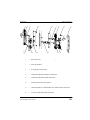
1. Außenbeschlag mit Antenne und Aussendrücker
2. Innenschild
3. Kupplungseinheit
4. Innendrücker
5. Drückerdorn
6. Innenbeschlag mit E-Modul
7. Befestigungsschrauben M5 (3 Stück)
8. Batterieschutzfolie
9. Batterieprint
10. Batterien Type AA Lithium (2 Stück)
11. M6 Befestigungsschraube für Drücker (aussen)
12. M6 Befestigungsschraube für Drücker (innen)
13. M3 Befestigungsschraube für Innenschild
14. Schloss (nicht enthalten)
15. Antennenkabel
16. Schließzylinder (nicht enthalten)
17. Richtungsgeber
18. Unterlagsplatte für Aussenschild
19. Befestigungsschraube M5 x 12 für Unterlagsplatte außen
20. Unterlagsplatte für Innenschild
21. Befestigungsschrauben M5 x 6mm für Innenbeschlag (2 Stück)
22. Senkkopfschraube M4 x 6mm (3 Stück)

4 k2evo707xy-2012-05 Kaba c-lever
DE zum Ersetzen von Rosetten
Kurzanleitung Installation
45°45°
45° 45°
17
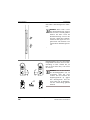
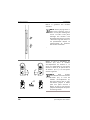
Vorhandene Rosettengarnitur entfer-
nen.
HINWEIS: Beim Kaba c-lever
für Rosettenmontage müssen
keine Löcher in der Tür gebohrt
werden. Der Kaba c-lever für
Rosettenmontage ist nur in der
Variante „Breitschild (54mm)“
erhältlich und eignet sich aus-
gezeichnet zum Ersetzen von
vorhandenen Rosettengarnitu-
ren.
Richtungsgeber (17) so in die Kupp-
lungseinheit einsetzen, dass bei Ver-
wendung an einer rechten Tür „R“
bzw. an einer linken Tür „L“ von vorne
zu lesen ist.
HINWEIS: Um das Einschieben
des Richtungsgebers (17) zu
erleichtern, muss bei einer
rechten Tür der Vierkant der
Kupplungseinheit (3) gegen
den Uhrzeigersinn und bei
einer linken Tür im Uhrzeiger-
sinn bis auf Anschlag gedreht
werden!

Installation Kurzanleitung
Kaba c-lever k2evo707xy-2012-05 5
zum Ersetzen von Rosetten
DE
23
3
5
1
1
3
15
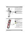
Den Drückerdorn (5) entsprechend
der Schlossnuss auswählen und in
den Vierkant der Kupplungseinheit (3)
stecken. Danach von oben mit Gewin-
destift (23) befestigen. Kupplungsein-
heit (3) am E-Modul anstecken und in
den Außenbeschlag (1) stecken.
ACHTUNG: Gewindestift (23)
muss immer nach oben zeigen!
Auf das Motorkabel achten!
Antennenkabel (15) anstecken und
seitlich der Kupplungseinheit (3) im
Außenschild (1) platzieren.
ACHTUNG: Antennenkabel
(15) nicht quetschen!
ACHTUNG: Insbesondere bei
direkter, als auch indirekter,
Berührung von Leiterplatten
können diese durch elektrosta-
tische Aufladung beschädigt
werden! Bei Montage- und
Wartungsarbeiten, immer ein
entsprechendes ESD-Erdungs-
band verwenden!

6 k2evo707xy-2012-05 Kaba c-lever
DE zum Ersetzen von Rosetten
Kurzanleitung Installation
1
15
5
19
18
16
15
1
5
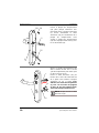
Die Unterlagsplatte für Außenschild
(18) vorsichtig in das Außenschild (1)
einsetzen. Dabei das Antennenkabel
(15) behutsam durch die Freistellung
der Unterlagsplatte führen. Anschlie-
ßend die Unterlagsplatte (18) mit den
Befestigungsschrauben (19) im
Außenschild (1) festschrauben.
Schließzylinder (16) in das Schloss ein-
schieben und gegen Verrutschen mit
der Zylinderschraube sichern (nicht
festschrauben).
Antennenkabel (15) durch die untere
Rosettenbohrung auf die Innenseite
der Tür führen. Anschließend das
Außenschild (1) auf die Türe aufste-
cken. Um die Kupplungseinheit (3)
zu entlasten, muss nach dem Auf-
stecken des Außenschildes (1) am
Drückerdorn (5) in Pfeilrichtung
angezogen werden.
HINWEIS: Antennenkabel (15)
nicht quetschen!

Installation Kurzanleitung
Kaba c-lever k2evo707xy-2012-05 7
zum Ersetzen von Rosetten
DE
Markierung
Stecker
20
5
16
15
7
1
6
21
10
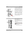
Auf der Innenseite der Tür die Unter-
lagsplatte für Innenschild (20) über
Drückerdorn (5) und Schließzylinder
(16) schieben. Dabei das Antennenka-
bel (15) durch die Aussparung in der
Unterlagsplatte (20) führen. Anschlie-
ßend die Unterlagsplatte (20) mit den
Befestigungsschrauben (7) mit dem
Außenschild (1) verschrauben
(Anzugsdrehmoment: 2,5 ±0,5 Nm).
Antennenstecker mit Krimpzange
(11674572 ECL.ZANGE.VERBIN-
DUNGSKABEL) wie abgebildet mon-
tieren.
Innendrücker vom Innenbeschlag (6)
abschrauben.
Innenbeschlag mit E-Modul (6) aufste-
cken und mit Befestigungsschrauben
(21) auf der Unterlagsplatte fest-
schrauben.
Batterien (10) einlegen und Batterie-
schutzfolie (8) zwischen die Batterien
stecken.
HINWEIS: An Türen zum
Außenbereich nur Lithium Bat-
terien verwenden!
Auf Polung der Batterien ach-
ten!

8 k2evo707xy-2012-05 Kaba c-lever
DE zum Ersetzen von Rosetten
Kurzanleitung Installation
15
4
22
Antennenkabel (15) am E-Modul an-
stecken.
Innendrücker (4) auf den Drückerdorn
(5) stecken und mit Senkkopfschrau-
ben M4 x 6mm (22) festschrauben.

Installation Kurzanleitung
Kaba c-lever k2evo707xy-2012-05 9
zum Ersetzen von Rosetten
DE
CLICK
12
13
2
door
thickness
23.3
23.3
Innenschild (2) aufstecken und von
unten mit Befestigungsschraube für
Innenschild (13) befestigen. Zuletzt
Befestigungsschraube für Drücker (12)
in den Innendrücker einschrauben.
HINWEIS: Für den Batterie-
tausch die Befestigungs-
schraube für Innenschild (13)
entfernen, Schraubendreher in
die Senkung der Schraube ein-
führen und das Inenschild (2)
abziehen.
Schließzylinder (16) festschrauben.
ACHTUNG: Zylinderüberstand
innen und außen mindestens
23,3mm!

10 k2evo707xy-2012-05 Kaba c-lever
DE zum Ersetzen von Rosetten
Kurzanleitung Installation
Notöffnung mit Batterienotgerät:
Batterienotgerät mittels Programmier-
kabel an die Programmierbuchse
anstecken. Berechtigtes User-Medium
vor die Antenne halten und den
Knopf am Batterienotgerät für ca. 1
Sekunde drücken. Danach kann die
Tür geöffnet werden.
ACHTUNG: Der Drücker bleibt
so lange eingekuppelt, bis die
Batterien gewechselt werden!

Installation Quick Guide
Kaba c-lever k2evo707xy-2012-05 11
for replace of rosettes
EN
1
17
5
11
3
15
14
19
18 16
20
7 21
22
12
6
4
98
10
2
13
1. External furniture with antenna and external lever handle
2. Inside shield
3. Coupling unit
4. Inside lever handle
5. Spindle
6. Internal furniture with e-module
7. M5 fixing screws (three)
8. Battery protection foil
9. Battery circuit board
10. Type AA lithium batteries (two)
11. M6 fixing screw for lever handle (outside)
12. M6 fixing screw for lever handle (inside)
13. M3 fixing screw for inside shield
14. Lock (not included)
15. Antenna cable
16. Locking cylinder (not included)
17. Direction pin
18. Support plate for outside shield
19. M5 x 12 mm fixing screws for support plate outside
20. Support plate for inside shield
21. M5 x 6 mm fixing screws for internal furniture (two)
22. M4 x 6 mm countersunk screws (three)

12 k2evo707xy-2012-05 Kaba c-lever
EN for replace of rosettes
Quick Guide Installation
45°45°
45° 45°
17
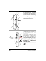
Remove existing rosette furniture.
NOTE: No drilling into the door
is necessary when using the
Kaba c-lever for rosette
assembly. The Kaba c-lever for
rosette assembly is only
available in the “wide plate”
version (54 mm) and is
excellently suited for replacing
existing rosette furniture.
Insert direction pin (17) into the
coupling unit so that the „R“ can be
read from the front on a right hand
door and the „L“ on a left hand door
during use.
NOTE: To ease insertion of the
direction pin (17), turn the
square spindle of the coupling
unit (3) anti-clockwise for right
hand doors, and for left hand
doors clockwise as far as the
fixed stop.

Installation Quick Guide
Kaba c-lever k2evo707xy-2012-05 13
for replace of rosettes
EN
23
3
5
1
1
3
15
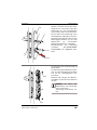
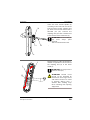
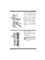
Select the lever handle spindle (5)
according to the lock hub and insert
into the square of the coupling unit
(3). Then secure it from above with a
threaded pin (23). Connect the
coupling unit (3) to the e-module and
insert into the external furniture (1).
AT TENT IO N: The threaded pin
(23) must always point
upwards.
Take care of the motor cord.
Plug the antenna cable (15) into the e-
module and position it to the side of
the coupling unit (3) in the outer
shield (1).
AT TENT IO N: Do not pinch the
antenna cable (15).
AT TENT IO N: Printed circuit
boards can be damaged by
electrostatic discharge. Direct
and indirect contact can result
in damage. Always wear a
suitable ESD earthing strap
when installing and repairing
equipment.

14 k2evo707xy-2012-05 Kaba c-lever
EN for replace of rosettes
Quick Guide Installation
1
15
5
19
18
16
15
1
5
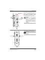
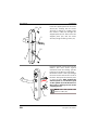
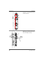
Insert the support plate for the outer
shield (18) carefully into the outer
shield (1). In doing so, carefully route
the antenna cable (15) through the
support plate release. Then secure the
support plate (18) into the outer
shield (1) using the fixing screws (19).
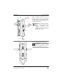
Push the locking cylinder (16) into the
mortise lock and secure against
movement with the locking cylinder
fastening screw (do not screw tight).
Route the antenna cable (15) through
the lower rosette hole to the inside of
the door. Then push the external plate
(1) onto the door. After putting the
external plate (1) on the door, pull
on the spindle (5) in the direction of
the arrow to relieve pressure on the
coupling unit (3).
NOTE: Do not pinch the
antenna cable (15).

Installation Quick Guide
Kaba c-lever k2evo707xy-2012-05 15
for replace of rosettes
EN
marking
plug
20
5
16
15
7
1
6
21
10
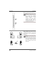
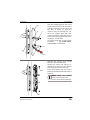
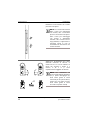
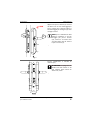
Push the support plate for the inside
shield (20) over the spindle (5) and the
locking cylinder (16) on the inside of
the door. In doing so, route the
antenna cable (15) through the cut-
out in the support plate (20). Then
screw the support plate (20) into the
outer shield (1) using the fixing screws
(7) (Torque: 2.5 ±0.5 Nm).
Fit antenna plug with crimping pliers
(11674572 ECL.ZANGE.VERBIN-
DUNGSKABEL) as illustrated.
Unscrew the internal lever handle
from the internal furniture (6).
Position the inside unit with the e-
module (6) and secure to the support
plate using the fixing screws (21).
Insert the batteries (10) and slip the
battery protection foil (8) between the
batteries.
NOTE: Only use lithium
batteries on outside doors.
Ensure correct battery polarity!

16 k2evo707xy-2012-05 Kaba c-lever
EN for replace of rosettes
Quick Guide Installation
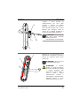
15
4
22
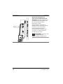
Plug the antenna cable (15) into the e-
module.
Place the inside lever handle (4) on
the spindle (5) and secure with M4 x 6
mm countersunk screws (22).

Installation Quick Guide
Kaba c-lever k2evo707xy-2012-05 17
for replace of rosettes
EN
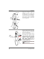
CLICK
12
13
2
door
thickness
23.3
23.3
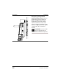
Attach the internal plate (2) and fasten
from below with a fixing screw for the
inner plate (13). Finally, screw the
fixing screw for the lever handle (12)
into the internal handle.
NOTE: To change the batteries
remove the fixing screw for the
inner plate (13), insert the
screwdriver into the screw
countersink and lift off the
internal plate (2) using the
screwdriver.
Secure locking cylinder (16)
AT TENT IO N: Cylinder standoff
inside and outside at least 23.3
mm.

18 k2evo707xy-2012-05 Kaba c-lever
EN for replace of rosettes
Quick Guide Installation
Emergency opening with the
battery emergency device: Use the
programming cable to attach the
battery emergency device to the
programming connector. Hold an
authorised medium in front of the
antenna and press the button on the
battery emergency device for approx.
1 second. The door can then be
opened.
AT TENT IO N: The lever handle
remains engaged until the
batteries have been replaced.

Installation Notice succincte
Kaba c-lever k2evo707xy-2012-05 19
pour remplacer des rosettes
FR
1
17
5
11
3
15
14
19
18 16
20
7 21
22
12
6
4
98
10
2
13
1. Garniture extérieure avec antenne et poignée extérieure
2. Plaque intérieure
3. Module d’accouplement
4. Poignée intérieure
5. Broche de poignée
6. Garniture intérieure avec module électronique
7. Vis de fixation M5 (3 pièces)
8. Film de protection des piles
9. Plaquette de piles
10. Piles type AA Lithium (2 pièces)
11. Vis de fixation M6 pour poignée (extérieure)
12. Vis de fixation M6 pour poignée (intérieure)
13. Vis de fixation M3 pour plaque intérieure
14. Serrure (non fournie)
15. Câble d'antenne
16. Cylindre de fermeture (non fourni)
17. Distributeur de direction
18. Plaque de compensation pour garniture extérieure
19. Vis de fixation M5 x 12 pour plaque de compensation extérieure
20. Plaque de compensation pour plaque intérieure
21. Vis de fixation M5 x 6mm pour garniture intérieure (2 pièces)
22. Vis à tête conique M4 x 6mm (3 pièces)

20 k2evo707xy-2012-05 Kaba c-lever
FR pour remplacer des rosettes
Notice succincte Installation
45°45°
45° 45°
17
Retirer la garniture des rosettes
existante.
NOTE: Aucun perçage dans la
porte n'est nécessaire avec le
Kaba c-lever pour montage de
rosace. Le Kaba c-lever pour
montage des rosettes n'est
disponible que dans la variante
« Garniture large (54 mm)» et il
est parfaitement adapté au
remplacement de garniture
des rosettes existantes.
Mettre en place le distributeur de
direction (17) dans le module
d'accouplement de manière à ce
qu'en cas d'utilisation sur une porte
ouvrant à droite, le „R“ puisse être lu
de devant (et le „L“ sur une porte
ouvrant á gauche.
NOTE: Pour faciliter
l'introduction de l'indicateur de
direction (17), le carré du
module d'accouplement (3)
doit être tourné dans le sens
anti-horaire jusqu'à la butée
pour une porte ouvrant à
droite, et dans le sens horaire
jusqu'à la butée pour une porte
ouvrant à gauche!
La pagina si sta caricando...
La pagina si sta caricando...
La pagina si sta caricando...
La pagina si sta caricando...
La pagina si sta caricando...
La pagina si sta caricando...
La pagina si sta caricando...
La pagina si sta caricando...
La pagina si sta caricando...
La pagina si sta caricando...
La pagina si sta caricando...
La pagina si sta caricando...
La pagina si sta caricando...
La pagina si sta caricando...
-
 1
1
-
 2
2
-
 3
3
-
 4
4
-
 5
5
-
 6
6
-
 7
7
-
 8
8
-
 9
9
-
 10
10
-
 11
11
-
 12
12
-
 13
13
-
 14
14
-
 15
15
-
 16
16
-
 17
17
-
 18
18
-
 19
19
-
 20
20
-
 21
21
-
 22
22
-
 23
23
-
 24
24
-
 25
25
-
 26
26
-
 27
27
-
 28
28
-
 29
29
-
 30
30
-
 31
31
-
 32
32
-
 33
33
-
 34
34


in altre lingue
- English: Kaba C-lever
- français: Kaba C-lever
- Deutsch: Kaba C-lever
Documenti correlati
Altri documenti
-
KTM 60712929100 Manuale del proprietario
-
 JMA DAKAR Manuale utente
-
Canon EOS C70 Guida utente
-
Canon Cinema EOS System Manuale utente
-
GROHE Eurosmart Cosmopolitan Series Application
-
Ducati SportTouring 2 Manuale del proprietario
-
EHEIM universal 2400 Manuale del proprietario
-
Beta 1937M Istruzioni per l'uso
-
Bosch POF1300ACE Manuale del proprietario
-
Zenner Minolist Istruzioni per l'uso
