
Eaton Industries (Austria) GmbH, Eugenia 1, A-3943 Schrems MA-PXS24_Standard.docx/04.2018
www.eaton.eu/documentation 1 150501507d/IL019188ZU
Technical Manual
page 3
PXS24… Standard
Technisches Handbuch
Seite 9
PXS24… Standard
Manuale Tecnico
pagina 16
PXS24… Standard
Manuel technique
page 22
PXS24… Standard
en
de
it
fr

Eaton Industries (Austria) GmbH, Eugenia 1, A-3943 Schrems MA-PXS24_Standard.docx/04.2018
www.eaton.eu/documentation 2 150501507d/IL019188ZU
Technical Manual
PXS24… Standard
CONTENTS
TechnicalManual(EN).............................................................................................................................................................................................4
Hazardwarnings...........................................................................................................................................................................4
ThePXS24system.........................................................................................................................................................................4
The“PXS24E…Standard“series.............................................................................................................................................5
Inputterminals...............................................................................................................................................................................5
Stand-aloneoperation.................................................................................................................................................................5
Temperaturerise...........................................................................................................................................................................5
Communication..............................................................................................................................................................................6
Grouperrormessages.................................................................................................................................................................6
Technicaldata.................................................................................................................................................................................7
TechnischesHandbuch(DE)...............................................................................................................................................................................10
Warnhinweise..............................................................................................................................................................................10
DasSystemPXS24......................................................................................................................................................................10
DieSerie„PXS24S…Standard“..............................................................................................................................................11
Eingangsklemmen......................................................................................................................................................................11
StandAlone...................................................................................................................................................................................11
Erwärmung...................................................................................................................................................................................11
Kommunikation..........................................................................................................................................................................12
Summen-Fehlermeldung.........................................................................................................................................................12
TechnischeDaten.......................................................................................................................................................................12
ManualeTecnico(IT).............................................................................................................................................................................................17
Avvertenzedipericolo.............................................................................................................................................................17
IlsistemaPXS24..........................................................................................................................................................................17
Laserie“PXS24…Standard”...................................................................................................................................................18
Morsettidialimentazione.......................................................................................................................................................18
Funzionamentoindipendente...............................................................................................................................................18

Eaton Industries (Austria) GmbH, Eugenia 1, A-3943 Schrems MA-PXS24_Standard.docx/04.2018
www.eaton.eu/documentation 3 150501507d/IL019188ZU
Riscaldamento ............................................................................................................................................................................. 18
Comunicazione ............................................................................................................................................................................ 19
Messaggi di errore di gruppo ................................................................................................................................................ 19
Dati tecnici .................................................................................................................................................................................... 20
Manuel technique (FR) .......................................................................................................................................................................................... 24
Attention ........................................................................................................................................................................................ 24
Le système PXS24 ...................................................................................................................................................................... 24
Série « PXS24... Standard » ..................................................................................................................................................... 25
Bornes d’entrée ........................................................................................................................................................................... 25
Utilisation séparée ..................................................................................................................................................................... 25
Échauffement ............................................................................................................................................................................... 25
Communication ........................................................................................................................................................................... 26
Messages d’erreur groupés par module ........................................................................................................................... 26
Données techniques .................................................................................................................................................................. 27

Eaton Industries (Austria) GmbH, Eugenia 1, A-3943 Schrems MA-PXS24_Standard.docx/04.2018
www.eaton.eu/documentation 4 150501507d/IL019188ZU
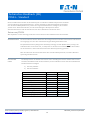
Technical Manual (EN)
PXS24… Standard
This manual describes the functioning of the Standard-series PXS24 and the “stand-alone” operation. The PXS24 system
allows for many possible combinations, which are described in detail in the “PXS24 system” manual.
Up-to-date information and the most recent version of this document are available at:
Eaton.com/PXS24
We recommend downloading the latest versions of all relevant documents prior to planning.
HAZARD WARN-
INGS
The PXS24 series has been developed specifically for overload-protected and short-circuit proof 24 V
power supply units, of the type commonly used in automation applications.
Whenever the modules are switched on (i.e. when operating voltage is applied) they are live (provid-
ed that the slide switch at the front is set to “I”)! If the unit has tripped (following an overload or
short circuit), switching it off and back on again will reset the trip.
Please refer to the technical data of the individual components, particularly the operating voltage and
the rated current.
THE PXS24 SYS-
TEM
There are many different options for combining the various components of the PXS24 series. To avoid
restricting this flexibility, two separate series with different functionalities are available.
1.) Economy: PXS24E-…
2.) Standard: PXS24S-…
Feature Economy Standard
Rated current 0-10A 0-16A
overload protection x x
Modular design x x
3 load outputs x x
Push-in terminals x x
Busbar (+/-) x x
Local status LED x x
Local control (on/off/reset) x x
Subsequent control x
Digital output (OK/tripped) x
Digital input (on/off/reset) x

Eaton Industries (Austria) GmbH, Eugenia 1, A-3943 Schrems MA-PXS24_Standard.docx/04.2018
www.eaton.eu/documentation 5 150501507d/IL019188ZU
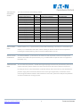
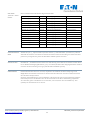
THE “PXS24E…
STANDARD“
SERIES
This manual describes the following models:
PXS24S-e2/F/ORT-IT 2A fix with input terminals PXS24S02A001
PXS24S-e4/F/ORT-IT 4A fix with input terminals PXS24S04A001
PXS24S-e6/F/ORT-IT 6A fix with input terminals PXS24S06A001
PXS24S-e8/F/ORT-IT 8A fix with input terminals PXS24S08A001
PXS24S-e10/F/ORT-IT 10A fix with input terminals PXS24S10A001
PXS24S-e13/F/ORT-IT 13A fix with input terminals PXS24S13A001
PXS24S-e16/F/ORT-IT 16A fix with input terminals PXS24S16A001
PXS24S-e2/F/ORT 2A fix without input terminals PXS24S02A002
PXS24S-e4/F/ORT 4A fix without input terminals PXS24S04A002
PXS24S-e6/F/ORT 6A fix without input terminals PXS24S06A002
PXS24S-e8/F/ORT 8A fix without input terminals PXS24S08A002
PXS24S-e10/F/ORT 10A fix without input terminals PXS24S10A002
PXS24S-e13/F/ORT 13A fix without input terminals PXS24S13A002
PXS24S-e16/F/ORT 16A fix without input terminals PXS24S16A002
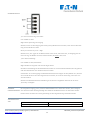
INPUT TERMI-
NALS
Articles marked “IT” (= “input terminal”) can be used individually (> see section on “stand-alone op-
eration”) or in combination with other articles. Should you wish to combine several components
(including for mixed operation), please consult the PXS24 system manual.
STAND-ALONE
OPERATION
An individual PXS24S-…/IT element can be used on its own to protect a channel. This requires the
selection of a model with input terminals (“IT”), as models without input terminals are supplied via
the busbar only.
TEMPERATURE
RISE
To ensure thermal protection, modules with high amperage should not be placed directly next to one
another, wherever possible. Please also refer to the technical data of the individual components.
De-rating: If three or more 16A modules are placed directly next to each other (in the specified tem-
perature range), these must be de-rated to 13A. For this type of application, we therefore recom-
mend using 13A modules instead. If 16A modules are to be used, please leave 1HP (18 mm) between
each of the modules for cooling purposes.

Eaton Industries (Austria) GmbH, Eugenia 1, A-3943 Schrems MA-PXS24_Standard.docx/04.2018
www.eaton.eu/documentation 6 150501507d/IL019188ZU
COMMUNICATI-
ON
“In” is used for control purposes:
Low: Module is live
High: No voltage at output
Note: The input is equipped with an internal pull-up resistor, so that the module is live without any
external connection.
Reset (remotely): Low > High
Note: An “off” signal always takes precedence (irrespective of whether it originates at the selector
switch at the front or at the “In” input), meaning the module will remain inactive until both signals
have switched to “on”!
“Out” trip signal:
Low: Module is live, no error
High: Module has tripped or was switched off manually
The GND connection at the communication port is intended for communication purposes only and
shall therefore not be loaded with currents over 200mA!
The communication port inputs and outputs conform to IEC/EN61131-2. It is therefore possible to
connect the module directly to a PLC, or to use it to control loads.
Note: The communication link is implemented via a dedicated port that is not available in the “Econ-
omy” series.
GROUP ERROR
MESSAGES
If individual error messages are not required, the trip outputs (“Out”) of several PXS24 modules can
be connected. A total of at most 30 modules can be connected in this way.
Note: This feature cannot be used simultaneously with the subsequent control.

Eaton Industries (Austria) GmbH, Eugenia 1, A-3943 Schrems MA-PXS24_Standard.docx/04.2018
www.eaton.eu/documentation 7 150501507d/IL019188ZU
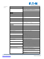
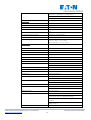
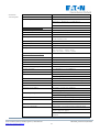
TECHNICAL
DATA
Marking CE
Certification UL508 + UL2367 (section 10 and 12)
Product standard Applicable sequences of:
EN60947-1, EN60947-5-1, EN61009-1,
EN61131-2 and EN61000-4-2
Details acc. to Werksnorm WN 1008
Electrical:
Operating voltage U
B
24V DC (16….30 V DC)
Rated current I
N
Fix; 2, 4, 6, 8, 10, 13, 16A
Current switch-off
(in case of overload or short circuit) Typically 1.3 x I
N
with active current limitation to
1,2 x l
N
Switch-off times for
electronic switch-off see time / current table
Capacitive loads Up to 20,000 μF
Inductive loads I
n
≤ 6A … τ
max
≤ 60ms
6A < I
n
≤ 10A … τ
max
≤ 12ms
10A < I
n
≤ 16A … τ
max
≤ 7,5ms
Mechanical:
Number of channels 1
Width 17.5 (1 HP)
Height 92.5mm
Depth 119.2mm
Input terminals (optional) 3 x LINE (+) and 3 x GND (-)
Output terminals 3 x LOAD (+) and 3 x GND (-)
Terminal type Push-in terminals
Terminal capacity 2.5mm² (flexible with ferrule)
4mm² (rigid)
Communication port 2 x remote signaling output (internally linked)
2 x remote signaling input (internally linked)
1x GND
Terminal type Push-in terminals
Terminal capacity 1 mm² (flexible with ferrule)
1.5mm² (rigid)
Busbar LINE (+) and GND (-); max. 80A
In different lengths up to 1m
Assembly Snap-fit onto the TH35 mounting rail (EN 60715)
Status LED Two-colored; Green = OK; Red = Tripped
Off = channel not in operation
Slide switch On/Off/Reset
Remote signaling output Tripped; via communication port
(in accordance with IEC 61131-2), class: 0.1A;
Type1/Type2 and Type3 digital inputs
Max. 30 PXS24V units can be connected simultane-
ously.
External signal sources up to 0.2A at 24V. (EATON
RMQ series,…)

Eaton Industries (Austria) GmbH, Eugenia 1, A-3943 Schrems MA-PXS24_Standard.docx/04.2018
www.eaton.eu/documentation 8 150501507d/IL019188ZU
Remote signaling input On/Off/Reset; via communication port
(in accordance with IEC 61131-2) Type 1/Type 3;
max. 30 PXS24V units can be connected simultane-
ously.
Subsequent control Via communication port
Text field 17.5 x 6mm
Degree of protection IP 20
Ambient temperature -30°C to 55°C
Storage temperature -40°C to 100°C :
Humidity 96h/95% rel. At 40°C acc to IEC 600068-2-78 non-
condensing
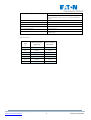
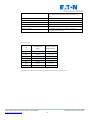
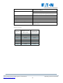
Switch-off times:
Rated Cur-
rent
Switch-off time
(typically)
active current
limitation
I
N
2A 460ms 1.2 x I
N
4A 240ms 1.2 x I
N
6A 160ms 1.2 x I
N
8A 108ms 1.2 x I
N
10A 108ms 1.2 x I
N
13A 75ms 1.2 x I
N
16A 75ms 1.2 x I
N

Eaton Industries (Austria) GmbH, Eugenia 1, A-3943 Schrems MA-PXS24_Standard.docx/04.2018
www.eaton.eu/documentation 9 150501507d/IL019188ZU
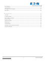
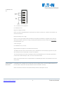
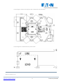
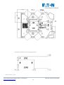
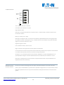
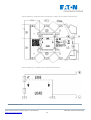
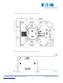
Circuit diagram and terminal assignment (for models with input terminals):
Circuit diagram for models without input terminals:
February 2018; V. 1.04

Eaton Industries (Austria) GmbH, Eugenia 1, A-3943 Schrems MA-PXS24_Standard.docx/04.2018
www.eaton.eu/documentation 10
150501507d/IL019188ZU
Technisches Handbuch (DE)
PXS24… Standard
Dieses Handbuch beschreibt das Zusammenspiel verschiedener PXS24 Komponenten. Zubehö r
wie Verschienung, Eingangsklemmen etc. werden ebenfalls in diesem Dokument beschrieben.
Fü r alle aktiven Komponenten ist jeweils eine eigene Dokumentation verfü gbar, die auch den
„Stand-alone“ Betrieb beschreibt, also die Verwendung der Komponente alleine.
Aktuelle Information und die aktuelle Version dieses Dokuments finden Sie unter:
Eaton.com/PXS24
Wir empfehlen vor der Planung jeweils die neueste Version aller Dokumente herunterzuladen.
WARNHINWEISE
Die Serie PXS24 ist fü r den Betrieb an ü berlastgesicherten und kurzschlussfesten 24V Netztei-
len ausgelegt, wie sie in der Automatisierungstechnik gebräuchlich sind.
Bei jedem Einschalten (Anlegen der Betriebsspannung) sind die Module aktiv (solange der
Schiebeschalter in der Front auf „I“ steht)! D.h. ein Auslösen nach U] berlast oder Kurzschluss
ist mit einem Aus- und wieder Einschalten der Betriebsspannung gelöscht!
Bitte beachten Sie die technischen Daten der einzelnen Komponenten, besonders Betriebs-
spannung und Nennstrom.
DAS SYSTEM
PXS24
Die Komponenten der PXS24 Serie lassen sich in unzä hligen Varianten miteinander nutzen.
Um diese Flexibilität nicht einzuschränken, sind verschiedene Serien mit unterschiedlichen
Funktionalitäten verfü gbar.
1.) Economy: PXS24E-…
2.) Standard: PXS24S-…
Funktion Economy Standard
Nennstrom 0-10A 0-16A
U] berlastschutz x x
Modularer Aufbau x x
3 Lastabgänge x x
Push-in Klemmen x x
Verschienung (+/-) x x
Lokale Status LED x x
Lokale Steuerung (on/off/reset) x x
Folgesteuerung x
Digitaler Ausgang (OK/ausgelöst) x
Digitaler Eingang (ein/aus/reset) x

Eaton Industries (Austria) GmbH, Eugenia 1, A-3943 Schrems MA-PXS24_Standard.docx/04.2018
www.eaton.eu/documentation 11
150501507d/IL019188ZU
DIE SERIE
„PXS24S… STAN-
DARD“
Dieses Handbuch beschreibt die folgenden Modelle:
PXS24S-e2/F/ORT-IT 2A fix mit Eingangsklemmen PXS24S02A001
PXS24S-e4/F/ORT-IT 4A fix mit Eingangsklemmen PXS24S04A001
PXS24S-e6/F/ORT-IT 6A fix mit Eingangsklemmen PXS24S06A001
PXS24S-e8/F/ORT-IT 8A fix mit Eingangsklemmen PXS24S08A001
PXS24S-e10/F/ORT-IT 10A fix mit Eingangsklemmen PXS24S10A001
PXS24S-e13/F/ORT-IT 13A fix mit Eingangsklemmen PXS24S13A001
PXS24S-e16/F/ORT-IT 16A fix mit Eingangsklemmen PXS24S16A001
PXS24S-e2/F/ORT 2A fix ohne Eingangsklemmen PXS24S02A002
PXS24S-e4/F/ORT 4A fix ohne Eingangsklemmen PXS24S04A002
PXS24S-e6/F/ORT 6A fix ohne Eingangsklemmen PXS24S06A002
PXS24S-e8/F/ORT 8A fix ohne Eingangsklemmen PXS24S08A002
PXS24S-e10/F/ORT 10A fix ohne Eingangsklemmen PXS24S10A002
PXS24S-e13/F/ORT 13A fix ohne Eingangsklemmen PXS24S13A002
PXS24S-e16/F/ORT 16A fix ohne Eingangsklemmen PXS24S16A002
EINGANGSKLEM-
MEN
Artikel mit „IT“ (= „input terminal“) kö nnen alleine (> siehe Abschnitt „stand alone“) oder im
Verbund mit anderen verschient verwendet werden. Für die Verwendung von mehreren Kom-
ponenten (auch gemischt), bitte das Handbuch PXS24 System beachten.
STAND ALONE Ein PXS24S-…/IT Element kann alleine zur Absicherung eines Kanals verwendet werden. Dazu
ist ein Modell mit Eingangsklemmen („IT“) zu wählen, Modelle ohne Eingangsklemmen werden
nur ü ber die Verschienung versorgt (siehe Handbuch PXS24 System).
ERWA] RMUNG
Um die Module thermisch zu schonen, empfehlen wir Module mit hoher Amperage nach
Möglichkeit nicht direkt aneinander zu bauen. Bitte beachten Sie auch die technischen Daten
der einzelnen Komponenten
Derating: Ab 3 Modulen mit 16A unmittelbar nebeneinander (im vorgeschriebenen Tempera-
turbereich) mü ssen die Module auf 13A derated werden. Fü r diese Anwendung empfehlen
wir entweder gleich 13A Module zu verwenden, oder zwischen den 16A Modulen je 1TE
(18mm) zur Konvektion frei zu lassen.

Eaton Industries (Austria) GmbH, Eugenia 1, A-3943 Schrems MA-PXS24_Standard.docx/04.2018
www.eaton.eu/documentation 12
150501507d/IL019188ZU
KOMMUNIKATION
„In“ wird zur Steuerung verwendet:
Low: Modul ist aktiv
High: Keine Spannung am Ausgang
Hinweis: Intern ist der Eingang mit einem pull-up Widerstand versehen, ohne externe Beschal-
tung ist das Modul also aktiv.
Reset (von der Ferne): Low > High
Hinweis: Ein „Aus“ (egal ob am Wahlschalter in der Front, oder ü ber den „In“ Eingang) hat im-
mer Vorrang, das Modul wird also inaktiv bleiben, bis beide „Ein“ sind!
„Out“ Auslö semeldung:
Low: Modul ist aktiv, kein Fehler
High: Modul hat ausgelöst oder wurde abgeschaltet
Die Masse Verbindung am Kommunikationsstecker ist nur fü r Kommunikationszwecke gedacht
und darf deshalb mit max. 200mA belastet werden!
Sowohl Ein- als auch Ausgänge am Kommunikationsstecker folgen der IEC/EN61131-
2, kö nnen
also sowohl direkt an eine SPS angeschlossen werden, als auch zur Steuerung von Lasten ver-
wendet werden.
Hinweis: Die Kommunikationsverbindung ist als Stecker ausgefü hrt und nicht in der Serie
„Economy“ verfü gbar.
SUMMEN-
FEHLERMELDUNG
Der Ausgelöst-Ausgang („Out“) mehrerer PXS24 Module kann verbunden werden, wenn lediglich
eine Summen-Fehlermeldung benötigt wird. Maximal 30 Module können so verbunden werden.
Hinweis: Diese Funktion kann nicht gleichzeitig mit der Folgesteuerung verwendet werden.
TECHNISCHE DA-
TEN
Kennzeichnung CE
Zertifizierung UL508 + UL2367 (Sektion 10 u. 12)

Eaton Industries (Austria) GmbH, Eugenia 1, A-3943 Schrems MA-PXS24_Standard.docx/04.2018
www.eaton.eu/documentation 13
150501507d/IL019188ZU
Produktnorm Anwendbare Sequenzen von:
EN60947-1, EN60947-5-1, EN61009-1,
EN61131-2 and EN61000-4-2
Details siehe Werksnorm WN 1008
Elektrisch:
Betriebsspannung U
B
24V DC (16….30V DC)
Nennstrom I
N
Fix; 2, 4, 6, 8, 10, 13, 16A
U] berlast- und
Kurzschlussstromabschaltung Typ. 1,3 x I
N
mit aktiver Strombegrenzung auf 1,2
x l
N
Abschaltzeiten fü r
elektronische Abschaltung siehe Zeit / Stromtabelle
Kapazitive Lasten Bis zu 20.000μF
Induktive Lasten I
n
≤ 6A … τ
max
≤ 60ms
6A < I
n
≤ 10A … τ
max
≤ 12ms
10A < I
n
≤ 16A … τ
max
≤ 7,5ms
Mechanisch:
Anzahl der Kanäle 1
Breite 17,5 (1TE)
Sockelmaß 92,5mm
Tiefe 119,2mm
Eingangsklemmen (optional) 3x LINE (+) und 3x GND (-)
Ausgangsklemmen 3x LOAD (+) und 3x GND (-)
Klemmenart Push-In Klemmen
Klemmenkapazität 2,5mm² (flexibel mit Adernendhü lse)
4mm² (starr)
Kommunikationsstecker 2x Fernmeldeausgang (intern gebrü ckt)
2x Fernmeldeeingang (intern gebrü ckt)
1x GND
Klemmenart Push-In Klemmen
Klemmenkapazität 1 mm² (flexibel mit Adernendhü lse)
1,5mm² (starr)
Verschienung LINE (+) und GND (-); max. 80A
In verschiedenen Längen bis 1m
Montage Schnappbar auf Tragschiene TH35 (EN 60715)
Status LED Zweifarbig; Grü n = OK; Rot = Ausgelöst;
Aus = Kanal nicht in Betrieb
Schiebeschalter Ein/Aus/Reset
Fernmeldeausgang Ausgelö st; ü ber Kommunikationsstecker
(entsprechend IEC 61131-2), Class: 0,1A;
Typ1/Typ2 und Typ3 Digital Eingänge
Max. 30 PXS24V kö nnen gleichzeitig verbunden
werden
Externe Signalquellen bis 0,2A@24V. (EATON
RMQ series,…)
Fernsteuereingang Ein/Aus/Reset; ü ber Kommunikationsstecker

Eaton Industries (Austria) GmbH, Eugenia 1, A-3943 Schrems MA-PXS24_Standard.docx/04.2018
www.eaton.eu/documentation 14
150501507d/IL019188ZU
(entsprechend IEC 61131-2) Typ1/Typ3; Max.
30 PXS24V können gleichzeitig verbunden wer-
den
Folgesteuerung U] ber Kommunikationsstecker
Textfeld 17,5 x 6mm
Schutzart IP 20
Umgebungstemperatur -30°C bis 55°C
Lagertemperatur -40°C bis 100°C
Luftfeuchtigkeit 96h/95% rel. Bei 40°C nach IEC 600068-2-
78 nicht kondensierend
Abschaltzeiten:
Nennstro
m
Abschaltzeit
(typ.)
aktive Strom-
begrenzung
I
N
2A 460ms 1,2 x I
N
4A 240ms 1,2 x I
N
6A 160ms 1,2 x I
N
8A 108ms 1,2 x I
N
10A 108ms 1,2 x I
N
13A 75ms 1,2 x I
N
16A 75ms 1,2 x I
N
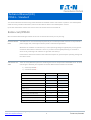
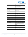
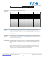
Schaltbild und Klemmenanordnung (fü r Modelle mit Eingangsklemmen):

Eaton Industries (Austria) GmbH, Eugenia 1, A-3943 Schrems MA-PXS24_Standard.docx/04.2018
www.eaton.eu/documentation 15
150501507d/IL019188ZU
Schaltbild bei Modellen ohne Eingangsklemmen:
Februar 2018; V. 1.04

Eaton Industries (Austria) GmbH, Eugenia 1, A-3943 Schrems MA-PXS24_Standard.docx/04.2018
www.eaton.eu/documentation 16
150501507d/IL019188ZU

Eaton Industries (Austria) GmbH, Eugenia 1, A-3943 Schrems MA-PXS24_Standard.docx/04.2018
www.eaton.eu/documentation 17
150501507d/IL019188ZU
Manuale Tecnico (IT)
PXS24… Standard
Questo manuale descrive il funzionamento della serie PXS24 Standard e la modalità di funzionamento indipendente. Il
sistema PXS24 rende possibili molteplici combinazioni, descritte nel dettaglio nel manuale del “sistema PXS24”.
Informazioni aggiornate e la versione più recente di questo documento sono disponibili sul sito:
Eaton.com/PXS24
Si consiglia di scaricare le versioni più recenti di tutti i documenti pertinenti prima della pianificazione.
AVVERTENZE DI
PERICOLO
La serie PXS24 è stata sviluppata appositamente per gli alimentatori a 24V DC protetti dal sovrac-
carico e a prova di corto circuito, comunemente utilizzati nelle applicazioni di automazione.
Quando i moduli sono accesi (ad es. quando viene applicata la tensione d'esercizio) essi si trovano
sotto tensione (a condizione che l’interruttore frontale a scorrimento sia impostato su "I")! Se
l'unità è scattata (dopo un sovraccarico o un cortocircuito), lo spegnimento e la riaccensione
dell'unità ripristinano il segnale di scattato.
Consultare i dati tecnici dei singoli componenti, in particolare la tensione d'esercizio e la corrente
nominale.
IL SISTEMA
PXS24
Sono disponibili molte opzioni per combinare i vari componenti della serie PXS24. Per evitare di
limitare questa flessibilità, sono disponibili due serie separate con funzionalità diverse.
1.) Economy: PXS24E-…
2.) Standard: PXS24S-…
Funzionalità Economy Standard
Corrente nominale 0-10A 0-16A
protezione da sovraccarico X X
Sistema modulare X X
3 uscite carichi X X
Morsetti ad innesto X X
Sbarra collettrice (+/-) X X
Stato locale LED X X
Comando locale (on/off/reset) X X
Comando conseguente X
Uscita digitale (OK/sganciato) X
Ingresso digitale (on/off/reset) X

Eaton Industries (Austria) GmbH, Eugenia 1, A-3943 Schrems MA-PXS24_Standard.docx/04.2018
www.eaton.eu/documentation 18
150501507d/IL019188ZU
LA SERIE
“PXS24…STANDA
RD”
Questo manuale descrive i seguenti modelli:
PXS24S-e2/F/ORT-IT 2A fisso con morsetti di alimentazione PXS24S02A001
PXS24S-e4/F/ORT-IT 4A fisso con morsetti di alimentazione PXS24S04A001
PXS24S-e6/F/ORT-IT 6A fisso con morsetti di alimentazione PXS24S06A001
PXS24S-e8/F/ORT-IT 8A fisso con morsetti di alimentazione PXS24S08A001
PXS24S-e10/F/ORT-IT 10A fisso con morsetti di alimentazione PXS24S10A001
PXS24S-e13/F/ORT-IT 13A fisso con morsetti di alimentazione PXS24S13A001
PXS24S-e16/F/ORT-IT 16A fisso con morsetti di alimentazione PXS24S16A001
PXS24S-e2/F/ORT 2A fisso senza morsetti di alimentazione PXS24S02A002
PXS24S-e4/F/ORT 4A fisso senza morsetti di alimentazione PXS24S04A002
PXS24S-e6/F/ORT 6A fisso senza morsetti di alimentazione PXS24S06A002
PXS24S-e8/F/ORT 8A fisso senza morsetti di alimentazione PXS24S08A002
PXS24S-e10/F/ORT 10A fisso senza morsetti di alimentazione PXS24S10A002
PXS24S-e13/F/ORT 13A fisso senza morsetti di alimentazione PXS24S13A002
PXS24S-e16/F/ORT 16A fisso senza morsetti di alimentazione PXS24S16A002
MORSETTI DI
ALIMENTAZIONE
Gli articoli con suffisso “-IT” (morsetto d’ingresso) possono essere utilizzati autonomamente
(-> confronta la sezione su “funzionamento indipendente”) o in combinazione con altri moduli. Se
desideri combinare molti componenti (compreso il funzionamento misto), consulta il manuale del
sistema PXS24.
FUNZIONAMEN-
TO INDIPENDEN-
TE
Un singolo elemento PXS24S-... -IT può essere utilizzato da solo per proteggere un canale. A tal
fine è necessario selezionare un modello con morsetti di ingresso ("...-IT"), in quanto i modelli
senza morsetti di ingresso vengono alimentati solo tramite la sbarra colletrice.
RISCALDAMENTO
Per garantire la protezione termica, i moduli con un amperaggio elevato non devono, ove possibi-
le, essere posizionati l'uno accanto all'altro. Fare inoltre riferimento ai dati tecnici dei singoli com-
ponenti.
Declassamento: Se tre o più moduli da 16A sono posizionati direttamente l'uno accanto all'altro
(nel campo di temperatura specificato), essi devono essere declassati a 13 A. Per questo tipo di
impianti si consiglia di utilizzare i moduli 13 A. Se è necessario utilizzare moduli da 16 A, lasciare 1
UM (18 mm) di spazio tra i moduli per permetterne il raffreddamento.

Eaton Industries (Austria) GmbH, Eugenia 1, A-3943 Schrems MA-PXS24_Standard.docx/04.2018
www.eaton.eu/documentation 19
150501507d/IL019188ZU
COMUNICAZIONE
“IN” viene utilizzato per i comandi:
Low: Mancanza di tensione in uscita
High: Modulo attivo
Nota bene: L’ingresso è dotato di un resistore interno, in questo modo il modulo è attivo senza
connessione esterna.
Reset (in remoto): Low > High
Nota bene: Un segnale “OFF” ha sempre la precedenza (indipendentemente che venga generato
dal selettore frontale o dall’ingresso “IN”), il modulo resterà quindi inattivo fin quando entrambi i
segnali non verranno spostati su “ON”!
Segnale di sgancio “OUT”:
Low: Il modulo è attivo, nessun errore
High: Il modulo è stato sganciato o è stato spento manualmente
La connessione verso terra sulla porta di comunicazione è prevista solo per scopi di comunicazione
e non deve essere quindi caricata con correnti al di sopra di 200 mA!
Gli ingressi e le uscite delle porte di comunicazione soddisfano i requisiti di IEC/EN61131-2. È
quindi possibile collegare il modulo direttamente al PLC o utilizzarlo per controllare i carichi.
Nota bene: Il collegamento di comunicazione è implementato tramite una porta dedicata non
disponibile nella serie “Economy”.
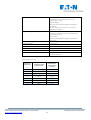
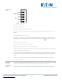
MESSAGGI DI ER-
RORE DI GRUPPO
Se non sono necessari messaggi di errore singoli, è possibile collegare le uscite di intervento
("OUT") di più moduli PXS24. In questo modo è possibile collegare fino a un massimo di 30 moduli.
Nota bene: Questa funzione non può essere utilizzata contemporaneamente al comando conse-
guente.

Eaton Industries (Austria) GmbH, Eugenia 1, A-3943 Schrems MA-PXS24_Standard.docx/04.2018
www.eaton.eu/documentation 20
150501507d/IL019188ZU
DATI TECNICI
Marcatura CE
Certificazione UL508 + UL2367 (Sezioni 10 e 12)
Standard prodotto Sezioni applicabili di:
EN60947-1, EN60947-5-1, EN61009-1,
EN61131-2 and EN61000-4-2
Dettagli secondo Werksnorm WN 1008
Dati elettrici:
Tensione di esercizio U
B
24 DC (16….30 V DC)
Corrente nominale
N
Fissa; 2, 4, 6, 8, 10, 13, 16A
Protezione da sovraccarico
o corto circuito
Generalmente 1,3 x In, con limitazione di corren-
te attivata a 1,2 x I
N
Tempi d’intervento per
lo sgancio elettronico
Si veda la tabella Tempo / Corrente
Carichi capacitivi fino a 20,000 μF
Carichi induttivi I
n
≤ 6A … τ
max
≤ 60ms
6A < I
n
≤ 10A … τ
max
≤ 12ms
10A < I
n
≤ 16A … τ
max
≤ 7,5ms
Dati meccanici:
Numero di canali 1
Larghezza 17,5 (1 UM)
Altezza 92,5 mm
Profondità 119,2 mm
Morsetti di alimentazione (opzionali) 3 x LINEA (+) e 3 x TERRA (-)
Morsetti di uscita 3 x CARICHI (+) e 3 x TERRA (-)
Tipo di morsetti Morsetti ad innesto
Sezione di collegamento 2,5 mm² cavo flessibile con puntalino
4mm² cavo rigido
Sezione di collegamento morsetti di co-
municazione
1 mm² cavo flessibile con puntalino
1,5 mm² cavo rigido
Porta di comunicazione
2 uscite di segnalazione remota (collegate inter-
namente)
2 ingressi di segnalazione remota (collegati in-
ternamente)
1x GND
Sbarra collettrice LINEA (+) e TERRA (-); max. 80 A
Sbarra collettrice
Assemblaggio
Disponibile in diverse lunghezze fino a 1m
Fissaggio a scatto sulla guida DIN TH35 (EN
60715)
LED di stato bi-colore
verde = OK, rosso = sganciato
OFF = canale non in uso
Interruttore a scorrimento On/Off/Reset
La pagina si sta caricando...
La pagina si sta caricando...
La pagina si sta caricando...
La pagina si sta caricando...
La pagina si sta caricando...
La pagina si sta caricando...
La pagina si sta caricando...
La pagina si sta caricando...
La pagina si sta caricando...
La pagina si sta caricando...
-
 1
1
-
 2
2
-
 3
3
-
 4
4
-
 5
5
-
 6
6
-
 7
7
-
 8
8
-
 9
9
-
 10
10
-
 11
11
-
 12
12
-
 13
13
-
 14
14
-
 15
15
-
 16
16
-
 17
17
-
 18
18
-
 19
19
-
 20
20
-
 21
21
-
 22
22
-
 23
23
-
 24
24
-
 25
25
-
 26
26
-
 27
27
-
 28
28
-
 29
29
-
 30
30


in altre lingue
- English: Eaton PXS24S-e13/F/ORT
- français: Eaton PXS24S-e13/F/ORT
- Deutsch: Eaton PXS24S-e13/F/ORT
Documenti correlati
-
Eaton PXS24S08A001 Technical Manual
-
Eaton PXS24E-e2/F-IT Technical Manual
-
-
-
-
Eaton 93PM-150(500) Safety And Installation Quick Manual
-
-
-
-
