- Tipo
- Istruzioni per l'uso

IT
EN
GRUPPO DI CONTINUITA' PER
TELECAMERE TVCC
Manuale di installazione, uso e manutenzione
Installation, operation and maintenance manual
UPS FOR CCTV CAMERAS
ART. / ITEM:
1936-GCONT
GRUPPO DI
CONTINUITA' PER
TELECAMERE TVCC
UPS FOR CCTV
CAMERAS
MADE IN ITALY

2
- Istruzioni originali -
1. INTRODUZIONE
Il gruppo di continuità è stato sviluppato per garantire a l'autonomia
delle videocamere in caso di assenza dell'alimentazione di rete
per le telecamere non PoE.
Al suo interno permette di alloggiare una batteria da 12 V e
1,3Ah garantendo quindi, ad esempio un'autonomia di 5 ore ad
una telecamera con 210 mA di consumo e LED IR accesi.
INDICE
1.1 CARATTERISTICHE TECNICHE
Tabella 1
Alimentazione 12 V
Batteria compatibile (art. 473LI1,3-12) 12 V 1,3 Ah
Temperatura di esercizio 5 ÷ 40 °C
Dimensioni 185 x 135 x 60 mm
Materiale ABS autoestinguente
Peso della confezione senza batteria 350 g
1. INTRODUZIONE ................................................................................................ 2
1.1 CARATTERISTICHE TECNICHE ........................................................... 2
1.2 CONTENUTO DELLA CONFEZIONE .................................................... 2
1.4 IDENTIFICAZIONE DELLE PARTI E DEI MORSETTI ........................... 3
2. INSTALLAZIONE............................................................................................... 3
3. MANUTENZIONE E VERIFICHE PERIODICHE ............................................... 4
4. SMALTIMENTO E ROTTAMAZIONE ................................................................ 4
Le informazioni riportate in questo manuale sono state compilate con cura,
tuttavia l’azienda produttrice non può essere ritenuta responsabile per
eventuali errori e/o omissioni. L’azienda si riserva il diritto di apportare in ogni
momento, e senza preavviso, miglioramenti e/o modiche ai prodotti descritti
nel presente manuale. L’azienda pone particolare attenzione al rispetto
dell’ambiente. Tutti i prodotti ed i processi produttivi sono progettati con criteri
di eco-compatibilità.
Il presente articolo è stato prodotto in Italia.
L’azienda ha un sistema di gestione della qualità certicato secondo la
norma ISO 9001:2008 (n° 4796 - A)
L’azienda ha un sistema di gestione ambientale certicato secondo la
norma ISO 14001:2004 (n° 4796 - E)
L’azienda ha un sistema di gestione della salute e sicurezza sul lavoro
certicato secondo la norma ISO 45001:2018 (n° 4796 - I)
The informations in this manual have been issued with care, anyway the
manufacturer will not be responsible for any errors or omissions. The
manufacturer reserves the rights to improve or modify the products described
in this manual at any times and without advance notice. The manufacturer
pays particular attention to environment respect. Each product and each
process have been designed with eco-compatibility criteria.
This product has been made in Italy.
The company has a certied system of quality management according
to ISO 9001:2008 (n° 4796 - A) standard.
The company has a certied system of environmental management
according to ISO 9001:2004 (n° 4796 - E) standard.
The company has a certied system of health and work security
management according to ISO 45001:2018 (n° 4796 - I) standard.
1. DESCRIPTION .................................................................................................. 2
1.1 TECHNICAL FEATURES ....................................................................... 2
1.2 PACKAGING CONTENTS ...................................................................... 2
1.4 PARTS AND TERMINAL BLOCK IDENTIFICATION .............................. 3
2. INSTALLAZIONE............................................................................................... 3
3. MAINTENANCE AND PERIODIC CHECKS ..................................................... 4
4. DISPOSAL AND SCRAPPING .......................................................................... 4
- Translation of the original instructions (original instructions in Italian) -
CONTENTS
1. DESCRIPTION
The UPS has been developed to guarantee the autonomy of the
cameras in case of absence of the power supply for non-PoE
cameras.
Inside it allows a 12 V and 1.3 Ah battery to be housed, thus
guaranteeing, for example, an autonomy of 5 hours for a camera
with 210 mA of consumption and IR LEDs on.
1.2 CONTENUTO DELLA CONFEZIONE
Tabella 2
Part. Identicazione
AGruppo di continuità
BIstruzioni
CCavo di collegamento
B
1.2 PACKAGING CONTENTS
Table 2
Ref. Identication
AUPS
BInstructions
CLinking cable
A
1.1 TECHNICAL FEATURES
Table 1
Power supply 12 V
Compatible battery (item 473LI1,3-12) 12 V 1,3 Ah
Working temperature 5 ÷ 40 °C
Dimensions 185 x 135 x 60 mm
Materials self-extinguishing ABS
Boc weight without battery 350 g
C

3
G
E
C
A
D
H
F
B
F
EF
G
H
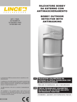
Tabella 3
Part. Identicazione delle parti
ABatteria 12 V 1,3 Ah (venduta separatamente art: 473LI1,3-12)
BScheda elettronica
CAlimentatore
DForo passaggio cavi
EFori per ssaggio a muro
FMicroswitch antiapertura
GCavi faston per batteria
HMorsettiera
+ 12 V proveniente dall'alimentatore (già cablato)
- Massa proveniente dall'alimentatore (già cablato)
0 Massa verso utenza
12 V Alimentazione verso utenza
AS Collegamento antisabotaggio N. A.
1.4 IDENTIFICAZIONE DELLE PARTI E DEI MOR-
SETTI
Fig. 1
+ - 0 12V AS
1.4 PARTS AND TERMINAL BLOCK IDENTIFICA-
TION
Per procedere all'installazione seguire quindi i passi riportati di
seguito:
• aprire il coperchio svitando le viti di chiusura presenti sul
coperchio;
• installare il fondo utilizzando i fori di ssaggio "E" (gura 1);
• collegare alla telecamera il cavo in dotazione per
l'alimentazione;
• collegare ai morsetti AS della scheda la linea di sabotaggio
24h proveniente dalla centrale;
• collegare l'alimentazione 220 Vca ai morsetti dell'alimentatore
secondo quanto riportato sui morsetti dello stesso;
• collegare i faston presenti sulla scheda alla batteria al
piombo avendo l'accortezza di rispettare le polarità;
• chiudere il coperchio.
2. INSTALLAZIONE
Table 3
Part. Part identication
A12 V 1.3 Ah Battery (sold separately item: 473LI1,3-12)
BElectronic board
CPower supply
DForo passaggio cavi
EWall xing holes
FAntitamper microswitch
GFaston cable for battery
HTerminal block
+ 12 V from the power supply (wired in factory)
- Ground from the power supply (wired in factory)
0 Ground to external device
12 V Power supply to external device
AS Antitamper N.O. link
2. INSTALLATION
To proceed with the installation, follow the steps below:
• open the cover by unscrewing the closing screws on the
cover;
• install the bottom using the xing holes "E" (gure 1);
• connect the supplied power cord to the camera;
• connect the 24h sabotage line coming from the control panel
to the AS terminals of the board;
• connect the 220 Vac power supply to the power supply
terminals as indicated on the power supply terminals ;
• connect the fastons on the card to the lead battery, taking
care to respect the polarities;
• close the lid.

001530/00947NA Rev0
3. MANUTENZIONE E VERIFICHE PE-
RIODICHE
Al ne di garantire il corretto funzionamento, è necessario sosti-
tuire la batteria tampone ogni 2 anni
ATTENZIONE! Per rimuovere sporcizie particolar-
mente evidenti NON utilizzare prodotti a base di clo-
ro, prodotti abrasivi oppure alcool.
1. Pulire il coperchio con un panno inumidito con acqua.
2. Ripassare con un panno asciutto.
4. SMALTIMENTO E ROTTAMAZIONE
1. Svitare le viti che tengono sso il coperchio frontale e rimuo-
verlo.
2. Scollegare la scheda: sulla morsettiera scollegare tutti i mor-
setti (v. Fig. 3).
3. Dividere le parti in base alla loro tipologia e smaltirle in accor-
do con le leggi vigenti.
ATTENZIONE!
Non disperdere nell’ambiente i componenti ed ogni
altro materiale del prodotto.
Rivolgersi a consorzi abilitati allo smaltimento ed al riciclag-
gio dei materiali.
3. MAINTENANCE AND PERIODIC
CHECKS
In order to ensure the correct work, is compulsory to replace the
battery every 2 years.
IMPORTANT!
Do NOT use chlorine-based or abrasive products
or alcohol to remove particularly noticeable dirt.
1. Clean the lid with a cloth dampened with water.
2. 2. Wipe with a dry cloth.
4. DISPOSAL AND SCRAPPING
1. Unscrew the screws that fasten the front lid and remove
it.
2. Disconnect the board: disconnect all the terminals on the
terminal block (see Fig. 3).
3. Divide the parts by type and dispose of them in accordance
with applicable laws.
IMPORTANT!
Do not dispose of the components or any other
product material in the environment.
Seek the assistance of companies authorised to dispose of
and recycle waste materials.
-
 1
1
-
2
-
3
-
4