
i
TYPE: SG200E
Hot beverage vending Machine
Saeco Group 200
Model:
ESPRESSO
OPERATION AND MAINTENANCE
WARNING: This instruction manual is intended exclusively for specialized personnel.

2
English
5
316
4
7
8
9
2
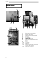
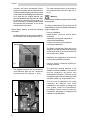
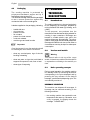
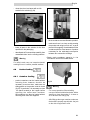
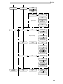
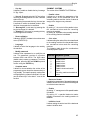
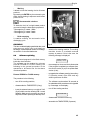
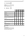
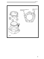
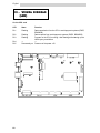
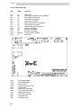
MAIN PARTS
1 Brew group and coffee grinder
2 Brewing hopper group
3 Sugar and stirrer dispensing group
4 CPU card
5 Cup dispenser
6 Payment system area
7 POWER card
8 Water circuit equipped with air-break
device
9 Pump
10 Tray socket
11 Data plate
12 Data plate showing the minimum and
maximum water pressure
13 Water mains connection
11
10
12
13

3
English
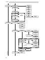
7 - PAYMENT SYSTEM
INSTALLATION .................... 24
7.1 Payment system installation on the
machine . ........................................... 24
7.2 Payment system installation on the
cabinet ............................................... 25
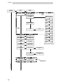
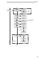
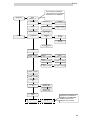
8 - PROGRAMMING AND
MAINTENANCE MENU ........ 26
8.1 Description of programming and
maintenance phase keys 27
8.2 Programming menu 27
8.2.1 Entering the programming menu 27
8.2.2 Structure of the programming menu 34
8.2.3 Functions of the programming menu 34
8.3 Maintenance menu 40
8.3.1 Access to the maintenance menu 40
8.3.2 Description of maintenance menu
messages 42
8.4 Software updating
(machine re-programming) 45
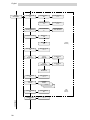
9 -
MAINTENANCE AND
INACTIVITY .........................
46
9.1 Cleaning and loading .......................... 46
9.1.1 Daily cleaning .................................... 46
9.1.2 Weekly cleaning ................................ 48
9.1.3 Product loading .................................. 49
9.2 Maintenance ...................................... 49
9.2.1 Scheduled and unscheduled
maintenance ...................................... 50
9.2.2 Brew group maintenance .................... 50
9.3 Adjustments ...................................... 51
9.3.1 Dose and grinding adjustment ............ 51
9.4 Cup releasing device cleaning and .....
adjustment ......................................... 52
9.5 Resin regeneration - where the water .
softner is provided .............................. 54
10 - INACTIVITY ......................... 55
11 - DISMANTLING .................... 55
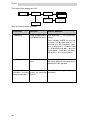
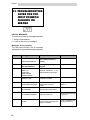
12 - TROUBLESHOOTING GUIDE
FOR THE MOST COMMON
FAILURES OR ERRORS ........ 56
13 - VISUAL SIGNALS (LEDs) ..... 60
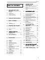
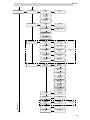
TABLE OF CONTENTS
1 - INTRODUCTION TO THE
MANUAL ............................. 4
1.1 Foreword ............................................ 4
1.2 Symbols used .................................... 4
1.3 General instructions............... ........... 5
1.4 Operator requirements ....................... 7
2 - TECHNICAL SPECIFICATIONS 7
3 - SAFETY STANDARDS ............. 8
3.1 Foreword ............................................ 8
3.2 General safety rules ........................... 8
4 - HANDLING AND STORAGE .. 9
4.1 Handling and transport ...................... 9
4.2 Storage ............................................ 9
4.3 Packaging ........................................ 10
5 - GENERAL TECHNICAL
DESCRIPTION ..................... 10
5.1 Permitted use .................................... 10
5.2 Versions and Models .......................... 10
5.3 Basic operating concepts................... 10
6 - INSTALLATION .................... 13
6.1 Positioning ......................................... 13
6.2 Receipt .............................................. 14
6.3 Unpacking .......................................... 15
6.4 Water mains connection .................... 16
6.5 Electric mains connection .................. 16
6.6 Machine start-up ................................ 17
6.7 Installation ......................................... 18
6.7.1 Cleaning and filling of resin-based
water softener .................................... 18
6.7.2 Water circuit filling ............................. 19
6.7.3 Cleaning the parts in contact with
foodstuff ............................................. 20
6.8 Product loading .................................. 21
6.8.1 Container loading ............................... 21
6.8.2 Label insertion ................................... 22
6.8.3 Cup loading ........................................ 22
6.8.4 Stirrer loading ..................................... 23

4
English
1 - INTRODUCTION TO
THE MANUAL
1.1 Foreword
Important
This publication is an integral part of the machine
and should be read carefully in order to use it in
a correct way. Complying with safety
requirements is also essential
This manual contains the technical information
necessary to carry out the procedures of use,
cleaning, installation and maintenance of the
vending machine mod. SG200E correctly.
Always consult this publication before carrying
out any operation.
Manufacturer: Saeco International Group
Via Panigali, 39 - 40041 Gaggio Montano (BO).
This manual should be kept with care and go
with the machine throughout its operational life,
also in case of changes of ownership.
If this manual should be lost or worn out, it is
possible to require another copy to the
Manufacturer or to an Authorized Service Centre.
In this event, please indicate the data on the plate
located on the back of the machine.
1.2 Symbols used
A number of symbols are used in this manual to
classify situations according to their degree of
danger, and that require technicians with different
skills.
The symbol is integrated with a message
suggesting operating procedures or behaviours
and providing useful information concerning the
machine performance.
Warning
This symbol indicates dangerous situations for
the users, supply operators and maintenance
technicians dealing with either the vending
machine or the product to be dispensed.
Important
This symbol indicates operations that keep the
machine in good working conditions, if properly
carried out.
Recommended solutions
This symbol indicates the procedures that make
the programming and/or maintenance
operations quicker.
User
This symbol indicates the machine user, who is
not authorized to clean or service the vending
machine.
Supply operator
It is used to indicate operations to be exclusively
carried out by personnel in charge of machine
supplying and cleaning.
Maintenance is exclusive task of the
maintenance technician, and cannot be
performed by the supply operator.
Maintenance technician
This symbol is used to indicate operations to be
only performed by specialized maintenance
personnel.
The maintenance technician is the only person
authorized to keep the MAIN SWITCH
ACTIVATION KEY, which allows disabling the
safety system.

5
English
It is the buyers responsibility to ascertain that
the machine operators have been trained and
informed of all the indications and
specifications contained in the documentation
supplied. Even so, the operator should be
aware of the potential risks that exist while
operating the automatic vending machine.
Operating reliability and the efficiency of the
machine performance are guaranteed only if
original spare parts are used.
The user will be held entirely responsible for
any modifications made on the machine. All
the operations necessary to keep the
machine in good working order, before and
during use, are users duty.
Altering and tampering with the machine
without prior consent of the manufacturer, will
release the latter from any liability for any
damage or injury resulting from, or connected
to the above modifications.
This manual reflects the state of the art of
the automatic vending machine at the
moment of the issue on the market. Possible
modifications, improvements or adjustments
that are made to machines that are
subsequently marketed, do not oblige the
Saeco International Group either to intervene
on the previously supplied machine or
consider it and the relevant manual to be
defective or inadequate.
: Read
This symbol indicates that the user should read
the instruction manual carefully before operating
the machine.
1.3 General instructions
: Warning
Before using the vending machine, read this
manual carefully. A good knowledge of the
information and instructions contained in this
document is essential for a correct use of the
vending machine, in compliance with essential
safety requirements.
Warning
Laddetto al rifornimento non deve per alcun
motivo accedere a quelle parti del distributore
automatico le cui protezioni sono bloccate da
mezzi che richiedano un utensile per essere
liberati.
For no reason whatsoever should the personnel
in charge of the machine reach those parts of
the machine that are protected by guards
requiring special instruments for their removal.
Some maintenance operations (to be carried out
solely by specialised technicians) expressly
require that certain safety devices be switched
off.
knowledge and absolute respect, from a
technical point of view, of the safety standards
and warnings contained in this manual, are
fundamental for installing, using and servicing
the machine under reduced risk conditions.
Vending machine operator is only allowed for
interventions under his own responsibility and
specialization.
The user should have a good knowledge of
all mechanisms of the machine, as far as he
is concerned.

6
English
However, the Saeco International Group,
whenever necessary and for valid reasons is
entitled to update existing manuals and send
to his customers all updating sheets that have
to be kept with the original manual. Any
technical problems that may arise can easily
be solved by consulting this manual. For
further information, contact the dealer where
the machine was purchased, or one of the
authorized service centres.
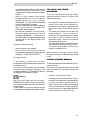
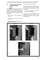
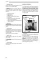
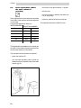
When calling, please, provide the following
information:
- the data written on the data plate located on
the rear side of the vending machine (fig. 1)
- The program version in the microprocessor
(see adhesive label on the component
mounted on the CPU card) (ref.1, fig. 2).
- The card code and version, to be found on
the component side of the CPU card (ref.2,
fig. 2).
Warning
It is absolutely forbidden to tamper with or modify
the data plate.
The Saeco International Group declines all
responsibility for injuries to people or damage to
things resulting from:
- incorrect installation
- inappropriate electrical and/or water
connection
- inadequate cleaning and maintenance
- unauthorized modification
- improper use of the vending machine
- non-original spare parts
The Saeco International Group will not be
obliged in any case to indemnify any damage
caused as a result of the forced inactivity of
the machine due to failure.
Installation and maintenance must be only
carried out by qualified technicians.
Use only specific foodstuffs suitable for
vending machines.
The automatic vending machine is not
suitable for outside installation. The machine
must be installed in dry places, with
temperatures not below 1°C and it must not
be installed in places where cleaning is made
with water hoses (e.g. large kitchens, etc.).
If at the time of installation, the usage
conditions are different from those
established or are subject to change over
time, please contact the manufacturer
immediately before using the machine.
Furthermore, always act in compliance with
national or local standards.
fig. 1
fig. 2
Data Plate
1

7
English
410
537.8
759.5
1.4 Operators requirements
To guarantee safety, three different machine
users are to be distinguished, each having
specific characteristics:
User
Access to the inside of the machine is forbidden
to the user.
Supply operator
The safekeeping of the access key to the inside
of the machine is entrusted to the Supply
operator by the Maintenance Technician. He has
the task of supplying the products, external
cleaning, activating and stopping the machine.
Warning
The Supply Operator is not authorized to carry
out operations that are indicated as competence
of the Maintenance technician in this publication.
Maintenance technician
Is the only person authorized to carry out and
start programming procedures for adjusting,
setting up and upkeep the machine.
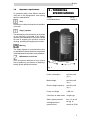
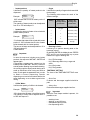
2 - TECHNICAL
SPECIFICATIONS
Weight 40 Kg
Overall dimensions See fig. 3
Power consumption see Data plate
(fig. 1)
Mains voltage: see Data plate
(fig. 1)
Electric voltage frequency. see Data plate
(fig. 1)
Power cord length 1,600 mm
Connection to water mains 3/8 gas type
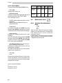
Water system pressure: from 1.5 up to 8
bar (fig. 4)
A-Weighted sound
pressure level: lower than 70 db
fig. 3

8
English
CUP DISPENSER
suitable for cups with 70-71 mm dia. and for cups
with 73 mm dia. through an adequate release
ring.
BOILER HEATING ELEMENTS
armoured types:
from 1,000 Watt for coffee boiler
CONTAINER CAPACITY
Coffee beans 2.0Kg
Instant coffee 0.6 Kg (instead of tea)
Granular milk 0.85Kg
Chocolate 1.7 Kg (or 2.6)
Tea 2.0Kg
Sugar 2.0Kg
Cups 195
Stirrers 185
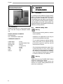
3 - SAFETY
STANDARDS
3.1 Foreword
In compliance with the Machine Directive 98/37/
EEC, Low Tension Directive 73/23/EEC and CE
Marking Directive 93/68/EEC, the Saeco
International Group has drawn up a technical file
on D.A. SG200 E vending machine at its plants,
acknowledging during the design phase the
regulations listed in the Declaration of Conformity
inside any vending machine.
3.2 General safety rules
Warning
- Before using the vending machine, read this
manual carefully.
- Installation and maintenance must only be
carried out by qualified technicians.
- For no reason whatsoever shall the operator
reach those parts of the machine that are
protected by guards requiring special
instruments for removal.
- Good knowledge and absolute respect, from
a technical point of view, of the safety
standards and danger warnings contained in
this manual, are imperative for installing,
using, servicing and maintaining the machine
in minimum minimum risk conditions.
Warning
Always disconnect the POWER CABLE before
servicing or cleaning the machine.
Under no circumstances neither service the
machine, nor remove safety guards before hot
parts have cooled down!
fig. 4
Data plate showing the minimum
and maximum water pressure

9
English
- Operating reliability and the efficiency of the
machine performance are only guaranteed if
original spare parts are used.
- The automatic vending machine is not
suitable for outside installation. The machine
must be installed in dry places, with
temperatures never below 1°C and it must
not be installed in places where cleaning is
made with water hoses (e.g. large kitchens,
etc).
- In order to guarantee the performance of the
machine, always keep the automatic vending
machine in perfect cleaning conditions.
- The Saeco International Group declines all
responsibility for injuries to people or damage
to things as a consequence of:
- Use individual protection devices during
installation, testing and maintenance.
incorrect installation
inappropriate electrical and/or water
connection
inadequate cleaning and maintenance
unauthorized modification
improper use of the vending machine
non-original spare parts
Important
It is forbidden to:
- Tamper with or cut off the safety systems
installed on the vending machine;
- Use water jets to clean the machine.
Furthermore, always act in compliance with
national or local standards.
4- HANDLING AND
STORAGE
4.1 Handling and transport
The transport of the vending machine should be
carried out by skilled personnel.
The vending machine is delivered on a pallet;
for handling purposes use a fork lift truck and
move it slowly in order to avoid any possible
overturning or dangerous oscillations.
Important
Avoid:
- lifting the vending machine with ropes or
presses;
- dragging the vending machine
- turning over or laying down the vending
machine during transport
- shaking the vending machine
Avoid the machine:
- being bumped into
- being overloaded with other parcels
- being exposed to rain, frost or heat sources
- being kept in damp places
4.2 Storage
In the event of storage, avoid any stacking of
several machines, keep them in a vertical
position, in dry places with temperatures not
below 1°C.

10
English
4.3 Packaging
The vending machine is protected by
polystyrene/cardboard angles and by a
transparent polypropylene film.
The automatic vending machine will be packaged
so as to ensure protection against any
mechanical and environmental agents.
Labels are applied on the packaging, indicating:
- handle with care
- do not overturn
- protect from rain
- do not stack
- protect from heat sources
- not shock resistant
- machine type and serial number
Important
Once the transport is over, the packaging should
be undamaged, which means it should not:
- show any crushed parts, sign of shocks,
buckling or breaking
- show wet parts or signs that could lead to
suppose its exposure to rain, frost or heat
- show signs of tampering
5- GENERAL
TECHNICAL
DESCRIPTION
5.1 Permitted use
The vending machine is to be used exclusively
for the dispensing of beverages, prepared by
mixing foodstuffs with water (by brewing, as to
coffee).
To this purpose, use products that the
manufacturer has declared as being suitable for
vending in open containers. Beverages are
brewed in suitable plastic cups, which the
machine dispenses automatically. The stirrer
used for mixing sugar is automatically dispensed.
Beverage should be drunk at once and under no
circumstances can they be kept for subsequent
consumption.
5.2 Versions and models
Warning:
This manual refers to the top-of-the -range
model: it is therefore possible to find descriptions
or explanations not relating to the machine you
have.
5.3 Basic operating concepts
During normal operation, the vending machine
is in standby mode. By introducing the amount
corresponding to the price displayed and by
pressing the key relevant to the desired
beverage, you will start the dispensing cycle. This
one basically consists of:
BEVERAGE SELECTION
The machine can dispense 8 beverages. A
beverage can be selected according to the
following conditions:
the vending machine has reached the set
temperature after start-up. Otherwise, once
a key is pressed, the display shows the
message PLEASE WAIT.

11
English
the available credit is sufficient or the vending
machine has been set in free mode. If this is
not the case, the display shows the message
INSERT ...;
there is no error condition that prevents
beverage brewing. If it is not the case the
display shows the error message
BEVERAGE... OUT OF SERVICE alternated
to a NOT AVAILABLE message;
the selected beverage has been enabled. If
this is not the case, the message NOT
AVAILABLE will be displayed;
the selected beverage is not prevented.
Otherwise, before pressing the key, the
message BEVERAGE ... alternated to a
NOT AVAILABLE message is displayed. After
pressing the key, the display shows NOT
AVAILABLE;
During hot beverage brewing:
- payment systems are disabled;
- the first line on the display shows the
programmable dispensing message (default
message is: WAIT FOR PRODUCT).
Beverage selection
If the vending machine has not been
programmed to freely dispense beverages insert
the required credit
Press the key corresponding to the beverage
requested. After beverage dispensing, the
message REMOVE CUP is displayed. Take the
beverage from the dispensing outlet.
Warning
Not to burn your hand, wait for the signal -
REMOVE CUP- before introducing your hand.
Do not open the dispensing outlet door while the
VM is brewing.
In case of failures or product missing during the
brewing phase, the display indicates the causes.
CUP, SUGAR AND STIRRER
DISPENSING
This is the first operation that the vending
machine activates (except for without cup
dispensing selection):
the cup bracket motor is activated and moves
under the cup chute. At the same time, it
operates the cup scrolls to separate the first
cup and let it drop into the special support
fork.
The same motor draws the cup under the
sugar dispenser there it stops for 2
seconds. In this way dispensing is enabled
and, where it is set or required, a stirrer is
dispensed. Finally, it sets the cup under the
beverage brewing nozzles.
The stirrer dispensing is controlled through a
solenoid which actuates the stirrer ejector.
The stirrer is then dropped into the cup by
means of the proper chute.
When selecting a beverage, sugar is dosed
through a motor that activates the sugar hopper
screw.
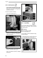
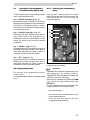
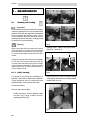
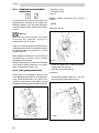
INSTANT BEVERAGE BREWING
This process takes place after dispensing of cup,
sugar and stirrer.
According to the type of beverage selected and
machine model, the following processes are
activated.
If present, the motor mixer starts.
the instant product solenoid valve (ref.1' fig.5),
located on the coffee boiler, starts and allows
to fill the mixer with the preset amount of
water. The pump (ref.2' fig.5) is then activated
and the preset amount of water dispensed,
under the control of an appropriate electronic
device (volumetric meter) (ref.3' fig.5).

12
English
1
2
3
the gear motor of the instant product activates
the screw, dispensing the desired amount of
product into the mixer.
once the pre-set amount of water and product
is dispensed, the mixer is disconnected.
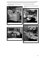
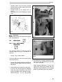
ESPRESSO COFFEE BREWING
This process takes place only after the
dispensing of cup, sugar and stirrer.
the grinder (ref.1 fig.6) is activated until the
quantity of coffee set on the dosing unit (ref.2
fig.6) is reached
the activation of the dosing unit solenoid (ref.
3 fig. 6) causes the door to open and, as a
consequence, the coffee is dispensed into the
cup.
the unit rotation gear motor activates, thus
moving the unit to the brewing position. The
coffee tablet is pressed simultaneously.
the pump brewing the set quantity of water
activates, under the control of an appropriate
electronic device (volumetric meter) (ref. 3
fig. 5).
the brew group gear motor is restarted, and
goes back to the rest position. During this
movement the coffee tablet is ejected.
The grinder and dosing unit activation sequence
can take place in reverse order, according to the
program selected (see programming menu).
fig. 5
fig. 6
1
3
2

13
English
6 - INSTALLATION
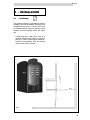
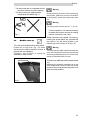
6.1 Positioning
The vending machine is not suitable for outdoor
installation. It must be installed in dry places, with
temperatures not below 1°C and it should not
be installed in places subject to explosion or fire
hazards, or where cleaning is done with water
jets.
- If positioned near a wall, there must be a
minimum distance of at least 5 cm from the
wall (fig. 7), so as to allow regular ventilation.
Under no circumstances cover the vending
machine with cloths or similar.
fig.7

14
English
6.2 Receipt
Upon receipt of the automatic vending machine,
it is necessary to check it has not suffered
damage during transport. If damage of any kind
is noticed, immediately place a claim with the
forwarder.
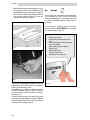
An envelope is supplied with the vending
machine, called CUSTOMER KIT. It contains
the objects shown in Fig. 10.
- Instruction manual.
- Powder tank plates and prices in
euro.
- Push-button panel selection plates.
- Instruction plates.
- Wiring and hydraulic diagram.
- Power cord.
- Safety switch key
(Technical engineer).
- Declaration of conformity
- When positioning the vending machine, check
its levelling by means of the adjustable feet
already fitted under the vending housing (fig.
8) or under the cabinet (fig. 9) Make sure that
the vending machine does not have an
inclination exceeding 2 degrees.
The Saeco International Group declines all
responsibility for troubles due to the failure in
observing the assembly rules.
If installation takes place in safety evacuation
corridors, make sure that the machine with the
door open assure sufficient space for people to
pass by (fig. 7).
In order to avoid the floor from getting dirty as a
result of accidental spillage of products, place a
sufficiently wide protection to cover the working
area under the vending machine.
fig.8
fig. 9
fig. 10

15
English
fig.11
fig.12
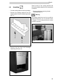
6.3 Unpacking
- Free the vending machine from the package.
- Remove the vending machine from the
transport pallet. Unloose its fastening screws
(fig. 11).
- Remove the key from the beverage
dispensing outlet (fig. 12).
Open the door of the vending machine and
remove the adhesive tape from the components
concerned.
- Remove polystyrene securing internal
components (fig. 13)
Warning:
The packing material must not be accessible to
unauthorized people, as it is a potential source
of danger. For the disposal please contact
qualified companies.
fig.13

16
English
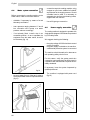
- connect the tap to the vending machine, using
a copper or nylon hose, suitable for foodstuff
and resistant to the supply pressure. Should
a flexible hose be used, it is necessary to
assemble the reinforcement bearing inside,
supplied with the machine.
- Use a 3/8 gas-type connection.
6.5 Power supply connection
The veding mahine is designed to operate with
single phase voltage at 230 Volts and is protected
by 6,3 A delay fuses.
We suggest checking the following:
- the mains voltage of 230 V should not exceed
a ± 6% fluctuation
- the power supply is suitable to the machine
- a differential protection system is connected
The machine should be earthed in observance
with operating safety rules in force.
For this reason, verify the system earth wire
connection to ascertain that it is efficient and in
compliance with national and European electric
safety standards.
If necessary, have the system inspected by
qualified personnel.
- The machine is equipped with power cord
(fig.16)
6.4 Water system connection
Before connecting the vending machine to the
water mains, make sure that the water is:
- drinkable, if necessary by means of a test
laboratory certification
- has a pressure ranging between 1.5 and 8
bar, otherwise use a pump or a water
pressure reducer accordingly.
- if not already fitted, install a tap in an
accessible position, so as to separate the
equipment from the water mains, should it
be necessary (fig. 14).
- let some water flow out of the tap in order to
eliminate possible traces of impurities and dirt
(fig.15).
fig.14
fig.15
fig.16

17
English
Safety switch
- The sockets that are not compatible with the
plug of the machine should be replaced.
- The use of extensions, adapters and/or
multiple plugs is forbidden (fig 17).
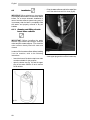
6.6 Machine start-up
The machine is equipped with a safety switch -
located on its top cover (fig. 18) which
disconnects the utilities whenever the door is
opened (see wiring diagram).
Therefore, open the door or unplug the
installation in case of need.
Warning
During the setting-up phase, before powering up
the machine, make sure you have connected it
to the hydraulic system and opened the water
tap.
Warning
The safety switch remains live (ref. 1, fig. 18)
- For some operations, it is however necessary
to operate with the door open but the vending
machine connected to the mains.
Skilled technicians may operate in this way, by
inserting the special plastic key, supplied with
the machine, into the switch located on the
machine top cover, turning it of 90° (fig. 18).
Warning
The opening and possible machine start with door
open must only be performed by authorized and
technically qualified personnel. Do not leave the
machine unattended while it is open.
Give the key to qualified and authorized personnel
only.
Whenever the machine is switched on a test
cycle is performed in order to verify the correct
position of the moving parts and the presence of
water and other products.
fig.17
fig.18

18
English
fig.20
fig.19
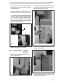
6.7 Installation
IMPORTANT: When switched on, the machine
automatically fills the water circuit and the related
boilers. For a correct automatic installation in
case of a water softener system being used, it
is necessary that the latter is completely filled
with water and properly relieved of any air
bubbles.
6.7.1 Cleaning and filling of resin-
based water softener
IMPORTANT: Before installing the water
softener in the machine and using it, clean the
resins and fill the water softener. Then install the
water softener already filled with water and
cleaned.
In order to fill in the water softener before installing
it on the machine, stick to the following
instructions:
- Insert the hose of the bottom tap into a drain
container suitable for this purpose.
- open the bottom tap (fig. 19) and the upper
plug of the water softener so as to remove
the air bubble.
- fill up the water softener and let the water flow
out of the drain hose until it is clear (fig.20).
- close upper plug and turn off the bottom tap

19
English
6.7.2 Water circuit filling
The machine automatically activates the pump
and starts filling the espresso coffee boiler.
IMPORTANT:
Before powering the machine, thus starting the
automatic installation:
1. Make sure that the water softener is filled with
water and the air bubbles removed.
2. Load the reachable columns of the cup holder.
NOTE:
If the filling of the boiler is not successful, the
machine cannot be set into service. A failure
message will be shown on the display. Should it
be the case, eliminate the cause and reset the
error recorded (section 8 Programming and
maintenance menu), then repeat the automatic
installation, switching the machine on once again.
After a testing phase on start-up, the machine
automatically fills the water circuit of the tray
equipped with a float and of the brew group boiler.
During this stage, the heating element of the
boiler remains automatically off. If the machine
detects that the boiler is already filled, it passes
to the heating stage.
The sequence of operations will be:
- insert the special key in the machine cover
switch
- on start-up of the machine, the filling of the
tray equipped with a float starts automatically,
while the machine carries out the automatic
testing phase.
During testing, the following components start
up in the given order:
- the brew group, so as to reach the correct
start-up position
- the cup holder, so as to load the first cup
column into the releasing device.
During the setting-up phase:
- the coffee boiler and the water tank are filled
up
- once the water circuit is filled, the heating
phase starts up, thus switching on
automatically the boiler heating element.
Recommended solutions
When the boiler is completely filled, wash the
mixer repeatedly in order to remove possible
residues from the hydraulic circuits. NB: see
section 8 - Programming and Maintenance
menu, in order to start test or cleaning brewing.
- After performing these operations, wait a few
minutes for the machine to reach service
temperature and make beverages available.

20
English
fig.22
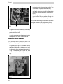
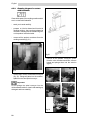
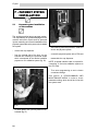
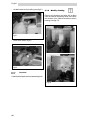
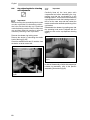
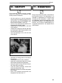
6.7.3 Cleaning the parts in contact
with foodstuffs
Clean all the parts of the vending machine which
are in contact with foodstuffs.
- wash your hands carefully.
- prepare a chlorine-based anti-bacterial
cleaning solution - they can be purchased at
chemists - following the concentrations given
on the product instruction label.
- remove all the product containers from the
vending machine (fig. 21).
- remove their covers, bushes and conveyors
(fig. 22). Plunge all parts into the solution,
apart from the steel spiral conveyor.
Important
Do not plunge the spiral conveyor into the
chlorine-based solution; clean it with washing up
detergent and rinse carefully.
- remove all the powder conveyors, water
funnels, mixer chambers and fans, silicone
hoses and plunge them into the solution
(fig.23).
fig.23
fig.21
La pagina sta caricando ...
La pagina sta caricando ...
La pagina sta caricando ...
La pagina sta caricando ...
La pagina sta caricando ...
La pagina sta caricando ...
La pagina sta caricando ...
La pagina sta caricando ...
La pagina sta caricando ...
La pagina sta caricando ...
La pagina sta caricando ...
La pagina sta caricando ...
La pagina sta caricando ...
La pagina sta caricando ...
La pagina sta caricando ...
La pagina sta caricando ...
La pagina sta caricando ...
La pagina sta caricando ...
La pagina sta caricando ...
La pagina sta caricando ...
La pagina sta caricando ...
La pagina sta caricando ...
La pagina sta caricando ...
La pagina sta caricando ...
La pagina sta caricando ...
La pagina sta caricando ...
La pagina sta caricando ...
La pagina sta caricando ...
La pagina sta caricando ...
La pagina sta caricando ...
La pagina sta caricando ...
La pagina sta caricando ...
La pagina sta caricando ...
La pagina sta caricando ...
La pagina sta caricando ...
La pagina sta caricando ...
La pagina sta caricando ...
La pagina sta caricando ...
La pagina sta caricando ...
La pagina sta caricando ...
La pagina sta caricando ...
La pagina sta caricando ...
La pagina sta caricando ...
La pagina sta caricando ...
La pagina sta caricando ...
La pagina sta caricando ...
La pagina sta caricando ...
La pagina sta caricando ...
-
 1
1
-
 2
2
-
 3
3
-
 4
4
-
 5
5
-
 6
6
-
 7
7
-
 8
8
-
 9
9
-
 10
10
-
 11
11
-
 12
12
-
 13
13
-
 14
14
-
 15
15
-
 16
16
-
 17
17
-
 18
18
-
 19
19
-
 20
20
-
 21
21
-
 22
22
-
 23
23
-
 24
24
-
 25
25
-
 26
26
-
 27
27
-
 28
28
-
 29
29
-
 30
30
-
 31
31
-
 32
32
-
 33
33
-
 34
34
-
 35
35
-
 36
36
-
 37
37
-
 38
38
-
 39
39
-
 40
40
-
 41
41
-
 42
42
-
 43
43
-
 44
44
-
 45
45
-
 46
46
-
 47
47
-
 48
48
-
 49
49
-
 50
50
-
 51
51
-
 52
52
-
 53
53
-
 54
54
-
 55
55
-
 56
56
-
 57
57
-
 58
58
-
 59
59
-
 60
60
-
 61
61
-
 62
62
-
 63
63
-
 64
64
-
 65
65
-
 66
66
-
 67
67
-
 68
68


Saeco Coffee Makers ESPRESSO SG200E Manuale utente
- Tipo
- Manuale utente
- Questo manuale è adatto anche per
in altre lingue
Altri documenti
-
 Necta Astro Installation, Operating And Maintenance Manual
-
 Necta Brio 250 Installation, Use And Maintenance Manual
-
ELEKTRA Professional espresso coffee machines Manuale utente
-
Philips RI 9913- SUP 016 E Manuale utente
-
Saeco ROYAL COFFEE BAR Manuale del proprietario
-
Nilfisk HSC585 Manuale del proprietario
-
-
Rancilio CLASSE 10 Use And Maintenance
-
-

