
Baumer Electric AG
Hummelstrasse 17 · 8501 Frauenfeld · Switzerland
Phone +41 52 728 11 22 · Fax +41 52 728 11 44
sales.ch@baumer.com · www.baumer.com
Printed in Switzerland · 06.20 · 81237067
Version 03
DE Montageanleitung
EN Assembly Instructions
FR Notice de montage
IT Istruzioni di montaggio
ES Instrucciones de montaje
RU Руководство по монтажу и
эксплуатации
MAGRES - EAM580 SSI
Absolute Drehgeber, Absolute encoder,
Codeur absolu, Encoder assoluto, Encoder ab-
solutos, Абсолютный датчик угла поворота
1. Empfohlenes Erdungskonzept/Recommended
grounding concept/Concept recommandé pour la
mise à la terre/Sistema di messa a terra consig-
liato/istema de puesta a tierra recomendado/
Экранирование корпуса
DE
2. Allgemein
Bestimmungsgemässer Gebrauch, Inbetriebnahme, Mon-
tage, Entsorgung siehe Beileger «Allgemeine Hinweise»
(11042373).
3. Zusätzliche Informationen
Diese Montageanleitung ist eine produktspezische Er-
gänzung zu den allgemeinen Dokumenten.
4. Wartung
Der Drehgeber ist wartungsfrei und darf nicht geöffnet
beziehungsweise mechanisch oder elektrisch verändert
werden. Ein Öffnen des Drehgebers kann zu Verletzungen
führen.
5. Montagehinweise
Auf korrekten Anbau und störungsfreien Betrieb achten.
Fremdkörper sind in ausreichendem Abstand zur Kupplung/
Statorkupplung zu halten. Antriebs- und Drehgeberwelle
über eine geeignete Kupplung, Drehmomentstütze verbin-
den (siehe Zubehör). Keine starre Verbindung vornehmen,
es ist in jedem Fall ein Ausgleichselement vorzusehen. Die
Montage mit nach oben gerichteter Welle bzw. Anschluss ist
zu vermeiden.
Hohlwelle: Bei Anwendungen mit hoher Schockbelastung
wird empfohlen den Drehgeber mit Loctite an der Welle zu
befestigen. Ein Betrieb an den Grenzen der Spezikation
kann zu einer Verringerung der Lebensdauer führen. Zen-
trische Montage ohne Krafteinwirkung sicherstellen (Siehe
Kapitel 9/10).
6. Technische Daten
Betriebsspannung:
4,5...30 VDC (UL Class 2)
SSI + HTL: 5,5...30 VDC (UL Class 2)
Betriebsstrom ohne Last: typ. 20 mA (24 VDC)
7. Schaltpegel
RS422 Gegentakt
High >2,3 V ≥+VS -2,2 V
Low <0,5 V <0,7 V
EN
2. General
Instructions for appropriate use, set-up, installation, dispo-
sal see insert «General Information» (11042373).
3. Additional informations
These assembly instructions are a product-specic supple-
ment to the general documents.
4. Maintenance
The encoder is maintenance-free and must not be opened
up nor mechanically or electronically modied. Opening up
the encoder can lead to injury.
5. Mounting instructions
Ensure correct installation and trouble-free operation. Fo-
reign objects must be kept at a sufcient distance from the
coupling / stator coupling. Connect drive and encoder shaft
with a suitable coupling (see accessories). Avoid rigid con-
nection. In any case the use of a torque element is required.
Mounting with shaft or connector pointing upwards has to
be avoided.
Hollow shaft: For applications with high shock load it is
recommended to x the encoder with Loctite to the shaft.
Operation at the limits of the specication can lead to a
reduction in service life. Ensure centric installation without
force (see chapter 9/10).
6. Technical data
Voltage supply:
4.5...30 VDC (UL Class 2)
SSI + HTL: 5.5...30 VDC (UL Class 2)
Consumption w/o load: typ. 20 mA (24 VDC)
7. Trigger level
RS422 Push pull
High >2.3 V ≥+VS -2.2 V
Low <0.5 V <0.7 V
FR
2. Générales
Instructions pour une utilisation appropriée, Mise en
service, Installation/Montage, Éliminatión voir les annexes
«Informations générales» (11042373).
3. Informations supplémentaires
Ces instructions de montage sont un complément spéci-
que aux documents généraux. Pour une utilisation en tant
que composant standard dans les fonctions de sécurité,
veuillez demander la «Note d‘application» correspondante.
4. Maintenance
Le codeur est sans entretien et ne doit pas être ouvert
ni mécaniquement ou électriquement modié. En cas
d‘ouverture du codeur, les ressorts risquent de provoquer
des blessures
5. Instructions de montage
Veiller à une installation correcte et à un fonctionnement
parfait. Maintenir les corps étrangers à distance sufsante
de l’accouplement. Raccorder les arbres d’entraînement et
du codeur au moyen d’un accouplement / ressort anti-rota-
tion approprié (voir accessoires). Ne pas raccorder l’arbre
du codeur et l’arbre d’entraînement de manière rigide. Dans
tous les cas, il convient de prévoir un élément de compen-
sation. Éviter le montage avec l’axe ou le raccord orienté
vers le haut.
Axe creux: en cas d’applications exigeant une résistance
aux chocs élevée, nous recommandons de xer le codeur
à l’axe à l’aide de Loctite. Une opération à la limite de la
spécication peut conduire à une réduction de la durée
de vie. Assurer une installation centrée sans force (voir le
chapitre 9/10).
6. Caractéristiques techniques
Alimentation:
4,5...30 VDC (UL Class 2)
SSI + HTL: 5,5...30 VDC (UL Class 2)
)
Courant de service sans charge: typ. 20 mA (24 VDC)
7. Niveaux électriques
RS422 Push pull
High >2,3 V ≥+VS -2,2 V
Low <0,5 V <0,7 V
IT
2. Generali
Istruzioni per un uso conforme, messa in funzione, mon-
taggio, smaltimento vedi allegati «Informazioni generali»
(11042373).
3. Ulteriori informazioni
Queste istruzioni di montaggio sono un supplemento speci-
co del prodotto ai documenti generali.
4. Manutenzione
L‘encoder non necessita di manutenzione, non deve
essere aperto e neppure essere sottoposto a modiche
meccaniche o elettriche. Un‘apertura dell‘encoder può
comportare delle lesioni.
5. Istruzioni di montaggio
Fare attenzione che il montaggio sia corretto e il funzio-
namento senza interferenze. Corpi estranei vanno tenuti
a debita distanza dal giunto di accoppiamento / accoppia-
mento dello statore. Albero motore e albero encoder vanno
collegati tramite apposito giunto di accoppiamento (vedi
accessori). Non eseguire alcun collegamento rigido. In ogni
caso va previsto un elemento di compensazione. Va evitato
il montaggio con l‘albero e/o il collegamento orientato verso
l‘alto.
Albero cavo: nelle applicazioni con elevata sollecitazione
improvvisa si consiglia di ssare l‘encoder all‘albero con
loctite. Un‘operazione ai limiti della specica può provocare
una riduzione della durata di vita. Garantire un‘installazione
centrica senza forzature (vedi il capitolo 9/10).
6. Dati tecnici
Tensione d’esercizio: 4,5...30 VDC (UL Class 2)
SSI + HTL: 5,5...30 VDC (UL Class 2)
Corrente di esercizio senza carico: typ. 20 mA (24 VDC)
7. Livello impostato
RS422 Push pull
High >2,3 V ≥+VS -2,2 V
Low <0,5 V <0,7 V
La pagina si sta caricando...

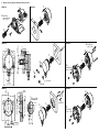
9. Montage / Mounting / Montage / Montaggio / Montaje / Mонтаж
EAM580-SC
1.
3.
2.
2.
M3 DIN 912
washers DIN 433
max. 1.2 Nm
3.
1.
EAM580-SY
2.
1.
3.
M3 DIN 912
max. 1.2 Nm
A
A
A-A
1
2
0
°
1
2
0
°
69ø
50 H7ø
ø0.4 A
3x
3x M4
A
A
A
A-A
50 H7ø
ø82
A
3.65 ±0.053x ø
ø0.3 A
1
2
0
°
1
2
0
°
ø24
B
ø
ø0.3 AB
2x
B
Detail
B
0.8 x 30°
0.5
1.5
1
5
°
R
0
.
2
3.6
3x M4
3x 10113222
2.
3.
1.
2.
1.
3.
M4 DIN 912
max. 1.2 Nm
4.
M4 DIN 934
max. 1.2 Nm
3x M3 or M4
2.
3.
1.
EAM580-SY
EAM580-SY
EAM580-SY
EAM580-SC

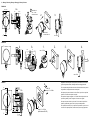
10. Montage / Mounting / Montage / Montaggio / Montaje / Mонтаж
EAM580-BA
EAM580-BE
EAM580-K
A
A
A-A
18max.
øD f6
18 ±13,5
68 ±0.2
1.
washers DIN 433
M4x6 DIN 912
max. 1.2 Nm
3.
max. 1 Nm
M4 DIN 912
washers DIN 125
2.
A
A
ø7
6±0.1
1 x 30°
22
3
10 ±0.1ø
21 ±0.1
max. 1.2 Nm
1.
2.
3.
max. 1 Nm
4.
A
A
A-A
50 H7ø
A
1.1±0.9
19.7 ±0.5()
0.2A
torque 1.3 +/-0.2 Nm
(shaft hardness 60 HRC)
3x M3 / 8.8
torque 1.3 +/-0.2Nm
2.
3.
1.
4.
Magnetläufer und Drehgeber nicht separieren. Andernfalls kann die Genau-
igkeit nicht garantiert werden, da Magnet und Sensor abgeglichen sind.
Do not separate magnet holder and encoder. Otherwise the accuracy cannot
be guaranteed, as magnet and sensor are adjusted.
Ne séparez pas le porte-aimant et le codeur. Sinon, la précision ne peut être
garantie, car l‘aimant et le capteur sont réglés.
Non separare il supporto magnetico e l‘ encoder. Altrimenti la precisione non
può essere garantita, perché il magnete e il sensore sono regolati.
No separe el soporte del imán y el encoder. De lo contrario la precisión no
puede ser garantizada, porque el imán y el sensor están ajustados.
Не отделяйте магнитный ротор от датчика. В противном случае точность
не может быть гарантирована, так как магнит и датчик отрегулированы.
-
 1
1
-
 2
2
-
 3
3
-
 4
4


Baumer EAM580-B - SSI Installation and Operating Instructions
- Tipo
- Installation and Operating Instructions
- Questo manuale è adatto anche per
in altre lingue
- English: Baumer EAM580-B - SSI
- français: Baumer EAM580-B - SSI
- español: Baumer EAM580-B - SSI
- Deutsch: Baumer EAM580-B - SSI
- русский: Baumer EAM580-B - SSI
Documenti correlati
-
Baumer EAM580-K - EtherCAT Installation and Operating Instructions
-
-
-
-
Baumer EAM360-B - CANopen® Installation and Operating Instructions
-
-
-
-
-