
®
Manuale di istruzioni • User's manual • Manuel d'instructions • Anleitung • Manual
de
instrucciones
1
HIGH
TECHNOLOGY
LEVEL

ITALIANO
ENG LI
SH
FRANCAIS
DEUTSCH
ESPANOL
Grazie di aver scelto un Many thanks for choosing Merci d'
avoir
choisi un Wir bedanken uns, daß Sie Gracias
po
r haber elegido
amplificatore
per
auto
a car amplifier AUDIOSYS- amplificateur
pour
autos
den
AUDIOSYSTEM-
un
amplificado
r
para
AUDIOSYSTEM serie HTL.
TEM
series
HTL.
AUDIOSYSTEM serie HTL.
Ve
rstärker der Serie HTL für automobil AUDIOSYSTEM
Frutto di una attenta ricer-
ca, tesa
al
miglior risultato,
gli amplificatori
serie HTL
garantiscono
prestazioni
esuberanti ehe non temo-
no confronti ripagando
la
fiducia accordata
da
chi,
ignaro o
consapevole ha
scelto senza dubbio
il
pro-
dotto giusto.
Ouesto manuale oltre alle
indicazioni per una corret-
ta
installazione e alle carat-
teristiche tecniche dei pro-
dotti offre precise indicazio-
ni
guida
sullo schema di
collegamento ehe affronte-
rete per
il
vostro impianto
CAR Hi-FI.
Complimenti
per
l'ottima
scelta.
2 AUDIOSYSTEM
HTL
1
02
•
202
•
402
The amplifiers series HTL
represent the fruits of a
careful
research for
the
best
result. They assure
exuberant
performances
which
do
not fear competi-
tion;
in
this way they pay the
trust
of all those
people
who, aware or unaware,
chose without
doubt
the
right product.
This
manual
offers,
to
-
gether with the indications
for a correct
installation and
with the
technical charac-
teristics
of
the products,
precise di rections
about
the connection scheme you
will deal with for your CAR
Hi-FI
system.
Many
compliments
on
your
very good choise.
Les
amplificateurs
serie Autoradios gewählt haben.
HTL representent
les
fruits Die Verstärker
der
Serie
d' une recherche attentive HTL sind
das
Ergebnis
qui vise au meilleur resultat. einer sorgfältigen Nachfor-
11
s assu rent
des
perfor- schung nach dem besten
mances exuberantes qui
Erfo
lg.
Sie ve
rsiche
rn
ne
craignent
pas
la
üppige
Lei
stungen
,
die
comparaison et qui recom- ohne Vergleich sind. So
pensent la confiance
de
belohnen sie das Vertrauen
ceux
qui, au
courant
ou al ler,
die,
bewußt
ode
r
non, ont choi
si
sans aucun
unbewußt,
das
ri
cht
i
ge
doute le juste produit. Produkt gewählt haben.
Ce
manuel
off
re
non
D
ie
vorliegende Anleitung
seulement les
direct
ions liefert außer der Angaben
pour
une correcte instal- für den korrekten Einbau
la
tion
et
les
caracte-
und
den
technischen
ristiques techniques des Produkteigenschaften auf
produits,
mais aussi
de
dem
Anschlußschema
precises indications sur
le
genaue Leitvorgaben für
schema de connexion que
Ihre HIFl-Anlage.
vous affronterez pour votre Herzlichen Glückwunsch!
appareil
CAR
Hi-FI.
Nos
compliments
pour
votre tres bon choix.
ser
ie
HTL. Fru
to
de
un
atento estudio para obte-
ner
el
mejor resultato, l
os
autoradios
serie
HTL
garantizan
prestacio
nes
exuberantes, que no temen
parag6n,
r
epagando
la
confianza
de
quie
n, sin
conocerlos o conciente
de
la elecci6n, ha el
ej
i
do
, s
in
ninguna duda,
el
producto
justo.
Es
te manual, ademas
de
las
in
dicaciones
para
obtene
r
una
co
r
rec
ta
i
nsta
laci6n y
de
las
ca-
racterfsticas tecnicas de
los productos, ofrece una
precisa gufa con
in
dicacio-
nes sobre
el esquema de
conexi6n del
au
toradio.
Felicitac
iones
por
la
eccelente el
ecc
i6n.

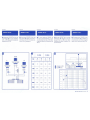
ITALIANO
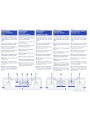
Nomenclatura
parti
collegamento
e
USO
1)
Contattiera per collegamento di
alimentazione (SUPPLY)negativo
(GND) accensione (ON) positivo
(BATI).
2)
Led
per indicazione funzione
Acceso
(ON) Protezione (SAFE).
3)
Prese RCA per collegamento di
ingresso
del segnale (INPUT).
4)
Contattiera per il collegamento
degli altoparlanti (OUTPUT).
5)
Comando per la regolazione del-
la sensibilita
di
ingresso (LEVEL).
6)
Comando per l'inserimento del
'BOOST 40
Hz'.
7)
Feritoie per la ventilazione inter-
na (forzata sui
modelli HTL 202 e
HTL
402).
8)
Piedini per favorire l'afflusso di
aria
alla ventola di raffreddamento
(solo sui modelli HTL 202 e HTL
402).
7
2
ENG
LI
SH
Nomenclature
of
the
parts,
connection
and
use
1)
Contacts for power connection
(SUPPLY) negative (GND) switch-
ing
(ON) positive (BATT).
2)
Led indicator for on (ON) and
safe
(SAFE) power.
3)
Jacks RCA for the input connec-
tion of the
signal (INPUT).
4)
Contacts for the speakers con-
nection
(OUTPUT).
5)
Unit for adjusting the input sen-
sitivity (LEVEL).
6)
Unit for inserting "BOOST 40
Hz"
7)
Vents for inner ventilation (forced
in
models HTL 202
and
HTL 402)
8)
Bearing feet which favour the air
inflow to the cooling fan (only in
models HTL 202 e HTL 402).
3 6 5
8
FRANCAIS
Nomenclature
des
parties,
connexion
et
usage.
1)
Contacts
pour
la
connexion
d'alimentation (SUPPLY) negative
(GND)
allumage
(ON)
positive
(SATT).
2)
Led
pour
indication fonction Al-
lume (ON) Protection (SAFE)
3)
Prises RCA pour connexion
d'
entree
du
signal (INPUT).
4)
Contacts pour la connexion des
haut-parleurs (OUTPUT).
5)
Commande pour le reglage
de
la sensibilite
d'
entree (LEVEL).
6)
Commande pour
I'
insertion
du
'BOOST 40 Hz"
7)
Fentes pour la ventilation inte-
rieure (forcee
dans
les modeles
HTL 202 et HTL 402)
8)
Pieds qui favorisent l'afflux d'air
au
ventilateur
de
refroidissement
(seulement HTL 202 e HTL 402).
7 7
DEUTSCH
Anschlußteile
, und
deren
Einsatz
'
1 ) Klemmenbrett für den Anschluß
von
Stromzuführung
(SUPPLY)
negativ (GND) Zündung (ON) positiv
(BATT).
2)
Led für die Anzeige der Funktion
eingeschaltet
(ON)
und
Schutz
(SAFE).
3)
RCA-Buchsen für Signaleingang
(INPUT).
4)
Klemmenbrett
für
Lautspre-
cheranschluß
(OUTPUT).
5)
Steuerung für die Einstellung der
Eingangsempfindlichkeit
(LEVEL).
6)
Steuerung
für
die Integration des
'BOOST
40
Hz'.
7)
Öffnungen für die lnnen-ventilation
(Luftbewegung
erzeugt
bei
den
Modellen HTL 202 und HTL 402).
8)
Füßchen
für den Zufluß
von
Luft
zum Kühlventilator (nur bei Modell
HTL 202 e HTL 402).
4
OUTPUT
8
ESPANOL
Nomenclatura
partes,
conexion
y
uso
1)
Contactos
para
conexi6n del
alimentador
(SUPPLY)
negative
(GND)
encendido
(ON)
positive
(BATT).
2)
Led
de
indicaci6n
de
funci6n
Encendido
(ON) Protecci6n (SAF
E)
3)
Ficha RCA para conexi6n del
ingreso
de
senal (INPUT).
4)
Contactos
para
la conexi6n
de
los altoparlantes (OUTPUT).
5)
Control para la regulaci6n
de
la
sensibilidad
de
entrada (LEVEL).
6)
Control para la conexi6n del
"BOOST
40
Hz"
7)
Hendiduras
para
la ventilaci6n
interna (for
zada
en
los
modelos
HTL 202 y HTL 402)
8)
Apoyos para favorecer el flujo
de
aire al ventilador refrigerante
(solamente en
los
modelos
HTL
202 e HTL 402).
1
7
SUPPLY
H
TL
102 •
20
2 • 402
AUOIOSYSTEM
3

1
1
ITALIANO
Consigli
utili
per
l'installazione
•
Prima
di
iniziare
il
montaggio
(o
lo
smontaggio) dell'amplificatore
scollegare
sempre
i
terminali
di
ali-
mentazione
della
batteria.
•
Ricollegare
i
terminali
solo
dopo
ehe
tutte
le
connessioni
(
comprese
quel-
le
di
segnale)
sono
state
ultimate
e
attentamente
controllate.
•
Posizionare
saldamente
l'amplifica-
tore
in
un
punto
sicuro
dell'auto
ehe
permetta
anche
una
buona
ventilazio-
ne
per
favorire
la
dissipazione
di
ca-
lore
dell'amplificatore.
•
Nel
caso
l'amplificatore
HTL
102
venga
installato
in
posizione
vertica-
le
fare
attenzione
ehe
le
alette
del
dis-
sipatore
non
siano
orizzontali
.1§1'
ma
verticali
al
terreno.
Will
•
Nei
modelli
HTL
202
e
HTL
402
non
rimuovere
i
piedini
di
ap-
poggio e
non
ostruire
le
feritoie
per
Ja
ventilazione
interna.
•
Usare
sempre
cavi
di
adeguata
se-
zione
per
ottenere
il
massimo
delle
prestazioni
da
tutti
i
componenti
del-
l'impianto.
• E
opportune
controllare
ehe
i
cavi
dell
'i
mpianto
siano
il
piu
possibile
se-
parati
onde
evitare
interferenze
dovu-
te
ai
campi
magnetici.
Un
posizionamento
ideale
dei
cavi
potrebbe
essere:
LATO
DX
Alimenta-
zione/Remote
-
CENTRO
Segnale
-
LA
TO
SX
Diffusori
•
Per
il
collegamento
dei
diffusori
as-
sicuratevi
sempre
di
aver
mantenuto
la
giusta
polarita.
4 AUOIOSYSTEM H
TL
10
2 •
202
•
402
ENGLISH
Useful
suggestions
for
the
installation
•
Before
beginning
the
installation
(or
the
removal)
of
the
amplifier,
always
disconnect
the
supply
terminals
of
the
battery.
•
Connect
the
terminals
again
only
after
you
have
completed
and
care-
ful
ly
checked
all
the
connections
(in-
cluded
the
signal
ones).
•
Firmly
position
the
amplifier
in
a
safe
point
in
your
car,
so
that
there
is
a
good
ventilation
to
promote
the
heat
dissi-
pation
of
the
amplifier.
•
Should
the
amplifier
HTL
102
be
installed
in
a
vertical
position,
be
care-
ful
that
the
fins
of
the
dissipator
are
not
horizontally
.1§1'
but
vertically
[iiill
to
the
ground.
•
In
models
HTL
202
and
HTL
402
do
not
remove
the
bearing
feet
and
do
not
obstruct
the
vents
for
inner
ventilation.
AIR
-
IN
•
Always
use
cables
of
adequate
sec-
tion
to
obtain
the
best
performances
from
all
the
components
of
the
sys-
tem.
•
lt
is
opportune
to
check
that
the
sys-
tem
cables
are
as
much
separate
as
possible
,
so
that
you
can
avoid
inter-
ferences
due
to
magnetic
fields.
An
ideal
location
of
the
cables
could
be:
RIGHT
SIDE
Supply/Remote
-
MIDDLE
Signal
-L
EFT
SIDE
Speak-
ers
•
When
connecting
the
speakers
,
be
always
sure
that
you
have
kept
the
right
polarity.
FRANCAIS
Conseils
utils
pour
I'
installation
•
Avant
de
commencer
Je
montage
(ou
le
demontage)
de
I' amplificateur,
debrancher
toujours
les
bornes
d'
alimentation
de
la
batterie
.
•
Ne
brancher
de
nouveau
les
bornes
qu
'
apres
que
toutes
1es
connexions
(y
compris celles
du
signal) ont
ete
achevees
et
attentivement
controlees
.
•
Positionner
solidement
I'
ampli-ficateur
dans
un
point
sQr
de
votre
voiture
qui
permette
aussi
une
bonne
ventilation
pour
favoriser
Ja
dissipation
de
chaleur
de
I'
amplificateur
.
•
Si
vous
installez
I'
amplificateur
HTL
102
en
position
verticale,
assurez-vous
que
les
ailettes
du
dissipateur
ne
sont
pas
horizontales,@
mais
verticales
[iiill
par
rapport
au
sol.
•
Dans
les
modeles
HTL 202
et
HTL
402
ne
pas
enlever
les
pieds
d'appui
et
ne
pas
obstruer
les
fentes
pour
la
ventilation
interieure.
A R 0 U T
• Utiliser toujours des cäbles de
section
appropriee
pour
obtenir
Je
maximum des performances de
toutes
les
parties
de
I'
appareil.
•
II
est
opportun
de
contröler
que
les
cäbles
de
I'
appareil
soient
le
plus
possible
separes
pour
eviter
taute
interference
causee
par
les
champs
magnetiques.
Un
ideal
positionnement
des
cäbles
pou
rr
ait
eire:
COTE
DROIT
Alimenta-
tion/Remote
-
CENTRE
Signal
-
COTE
GAUCHE
Diffuseurs
•
Pour
la
connexion
des
diffuseurs,
assurez-vous toujours
d'
avoir
maintenu
la
juste
polarite.
DEUTSCH
Nützliche
Hinweise
für
den
Einbau
•
Vor
dem
E
inbau
(oder
vor
dem
Aus-
bau)
des
Verstärkers
stets
die
Strom-
zufuhrkabel
von
der
Batterie
abtrennen
.
• Die
Anschlüsse
erst
nach
Beend
i-
gung
und
genauer
Überprüfung
aller
Anschlüsse
(auch
die
Si
gnalanschlüs-
se)
vornehmen.
•
Den
Verstärker
fest
an
einer
gesicher-
ten
Stelle
im
Auto
unterbringen,
die
gut
ventiliert
sein
soll,
um
den
Wärmeab-
zug
des
Verstärkers
zu
begünstigen.
•
Wenn
der
HTL
102
Verstärker
verti-
kal
eingebaut
wird
,
darauf
achten
,
daß
die
Kühlrippen
des
Wärmeab-zugs
nicht
horizontal
~sondern
ve
rt
ikal
[i]iII
zum
Boden
liegen.
•
Bei
den
Modellen
HTL
202
und
HTL
402
dürfen
die
Stützfüßchen
nicht entfernt werden!
Es
ist unbe-
dingt darauf
zu
achten
daß
die Öff-
nungen für die Innenventilation
nicht verstopft werden!
AIR
-
IN
•
Stets
Kabel
mit ausreichendem
Querschnitt benutzen, um
Höchstleistungen
aller
Bauteile
der
Anlage
zu
garantieren.
•
Die
Kabel
sind
voneinander
getrennt
zu
halten,
um
Störungen durch
Magnetfelder
zu
unter-binden.
Die
ideale
Positionierung
der
Kabel
könnte sein:
RECHTE
SEITE
Stromzufuhr/Remote
-MITIE
Signal
-
LINKE
SE
IT
E
Diffuser
•
Für
den Anschluß der Diffuser
versichern
Sie
sich
stets,
die
richtige
Polarität
eingehalten
zu
haben.
ESPANOL
Consejos
utiles
para
la
instalacion
•
Antes
de
comenzar
a
armar
(o
desarmar)
el
autoradio
, desconec-
tar siempre los terminales de
alimentaci6n
de
la
baterfa.
• Reconectar
los
terminales solo
despues
que
todas
las
conexiones
(incluso
aquellas
de
senal)
hayan
sido
ultimadas
y
atentamente
controladas.
•
Fijar
el
autoradio
en
un
punto
seguro
del
vehfculo
que
perm
i
ta
una
buena
ventilaci6n, para f avorecer
la
dispersi6n
de
calor
del
autoradio.
•
Si
el
autoradio
HTL
102
viene
instalado en posici6n vertical,
controlar
que
las
aletas
del
disipador
non
esten
horizontales
~
sino
Will
verticales
al
terreno.
•
En
los
modelos
HTL
202
y
HTL
402
no
quitar
Ja
base
de
apoyo,
ni
obstruir
las
hendiduras para
Ja
ventilaci6n
interna.
•
Utilizar
s!empre
cables
de
diametro
adecuado para
obtener
el
maximo
del rendimiento
de
todos los
componentes
del
equipo.
•
Controlar
que
todos
los
cables
del
equipo esten lo mas separado
posible, para evitar interferencias
debidas a
campos
magneticos.
Una
posici6n
ideal
para
los
cables,
podrfa ser: LADO DERECHO
Alimentador/Remote
-
CENTRO
Senal
LA
DO
IZQUIERDO
Difusores
•
Para
Ja
conexi6n
de
los
difusores,
asegurarse siempre de haber
mantenido
la
polaridad
correcta.

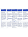
ITAUANO
Collegamento
altoparlanti
3)
Stereo 4 ohm
4)
Stereo 2 ohm
5)
Mono 4 - 8 ohm
6)
Stereo 4 ohm con subwoofer
mono 4 - 8 ohm. A
lato i valori delle
bobine
mH
(L) e dei condensatori
uF
(C) per costruire filtri passa-bas-
so e
passa-alto con pendenza di
6
dB
oct. (7)
L
II
1 1
1
"'c\._s;;J__rJ}
~
6 AUOIOSYSTEM
HT
L 102 -
20
2 •
4C2
ENG
LI
SH
Speakers
connection
1
3)
Stereo 4 ohm
4)
Stereo 2 ohm
5)
Mono 4 - 8
ohm
6)
Stereo 4
ohm
with subwoofer
mono 4-8
o~m.
Beside you can find
the
values of the coils mH (L) and
condensers uF (C) to
build low-
pass
and
high-pass
filters with
slope of 6 dB oct. (7)
R
FRANCAIS
Connexion
haut-parleurs
3)
Stereo 4 ohm
4)
Stereo 2 ohm
5)
Mono 4 - 8 ohm
6)
Stereo 4 ohm avec subwoofer
mono 4-8 ohm. A
cöte
il
y a les
valeurs
des bobines mH (L) et
des
condensateurs
uF (C)
pou
r
construire
les filtres passe-bas
et
passe-haut avec pente de 6 dB oct.
(7)
DEUTSCH
Lautsprecheranschluß
3)
Stereo 4 Ohm
4)
Stereo 2 Ohm
5)
Mono 4 - 8 ohm
6)
Stereo 4 Ohm mit Mono-Sub-
Woofer mit 4-8
Ohm. Auf der Seite
sind die Werte
de
r Spulen mH (L)
und
der Kondensatoren
uF
(C) für
Hoch-und
Baßtonfilter
mit
einer
Steilheit
von
6
dB
oct.
(7)
aufgeführt.
II
~
:
:
~
1
~
~
L
II
II
R
- +
~
:
:
~
II
II
ESPANOL
Conexion
de
tos
altoparlantes
1
1
3)
Stereo 4 ohm
4)
Stereo 2 ohm
5)
Mono 4 - 8 ohm
6)
Stereo 4 ohm con subwoofer
mono 4-8 ohm.
Al lado los valores
de
las bobinas mH (L) y
de
los
condensadores
uF
(C)
para
construir filtros pasa-bajos y pasa-
altos, con potencia
de
6
dB
oct. (7)
•

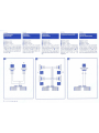
ITALIANO
"BOOST
40
Hz"
8)
1 nserendo
il
'
BOOST
40
Hz
' con
il comando (a)
si
ha
un
incremen-
to
di
+4
dB
nella sezione bassi
alla
frequenza di
40
Hz
.
SUB
L
•
•
ENG
LI
SH
'
"BOOST
40
Hz"
8)
lf
you
insert '
BOOST
40
Hz
'
with
the
control (a)
there
will be
an
in-
cr
ement
of
+4
dB
in
the
bass
sec-
tion at
40
Hz
frequency.
~
Hz
R
80
100
130
150
200
260
FRANCAIS
"BOOST
40
Hz"
8)
Si
vous
i
nserez
le
"
BOOST
40
Hz
' par la commande (a),
il
y
aura
un
accroissement de +4
dB
dans
la
section grave a
la
frequence de
40
Hz.
4ohm
8ohm
L
c
L
c
mH
uF
mH
uF
8
500
16
250
6.4
400
12.8
200
4.9
300
10
150
4.
25
270
8.5
135
3.2
200
6.4
100
2.45
150
4.9
75
DEUTSCH
"BOOST
40
Hz"
8)
Wird
der '
BOOS
T
40
Hz
' mit der
Steuerung
(a) integriert, wird
ein
Zuwachs
von
+4
dB
in
den
tiefen
Sektionen
bei
einer
Frequenz
von
40
Hz
erreicht.
O
(a)
on
(+4dB)
a
(a)
off
(flat)
"""
•oooo
1--
'""'
0 0
e
'""
•ooo
·
1100
10
L
~
-
--
1
~.
r~
,j
40 100
ESPANOL
1
"BOOST
40
Hz"
8)
Conectando
el
"
BOOST
40
Hz"
con
el
comando (a)
se
obtiene
un
incremento de +4
dB
en
el
sector
bajos,
en
la frecuencia de
40
Hz.
a
111
i
III
1
1
1
1
1
' 1 '
'
1
1
\
1
0.
1
00.,...
HTL
102
-
202
•
402
AUDI
OSYSTEM
7

-·
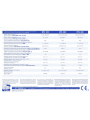
Carattenst1che
Tecniche
/
Technical
charactenstics /
Ca
r
actenst1ques
techniques /
HTL
102
HTL
202
HTL
402
Technische Eigenschaften/
Caractenst1cas
tecnicas /
14
,4 V
Po
t
en
za /
Powe
r / Puis
sance
/
Le
istung /
Poten
cia /
stereo
RMS
4
ohm
•
(2
ohm)
Potenza
/
Po
wer/
Puis
sance /
Le
ist
ung
/
Poten
cia /
mono
RMS
4
ohm
•
(8
ohm)
Rendim
en
to
glo
ba
le /
Overall
efficiency /
Ren
deme
nt
global /
Leis
tun
g über a
ll
e
s/
Rendimiento global /
max
power
4
ohm
Risposta in Frequenza /
Fre
quency response /
Reponse
en
freque
nce /
Frequenzantwort / Respuesta
en
frequencia / (·3dB)
D
is
t
or
sio
ne
/ Di
st
ortion / Distorsion /
Verzerrung
/ Distorsi6n /
(THD)
stereo
4
ohm
max
power
50+5
0 (95+95) w
190 (
100)
w
58%
5 -
110
.000 Hz
0.
02
%@
1
KHz
Distorsione
di
lntermodulaz
i
one
/
lntermodulation
distortion
/
Distorsio
n d'
intermodulation
/
lntermodulat
i
onsverzerru
ng / Di
st
o
rs
i6n de
lntermodu
l
ac
i
6n
/ 4 ohm
max
power
DIM
100
0,
004
%
Seg
n
ale-
r
umore
lineare /
Lin
ear noi
se
-signal /
S1gn
al-
bruit lineaire /
Li
n
earer
Ver
l
au
f Sign
al-
T
on/
S
en
al-rui
do
l
ineal
/
min
sens.
(pes.
A)
Fattore
smorzamento /
Damp
i
ng
factor /
Fa
ct
eu
r d' amorti
ssement
/
Dämpfungsfaktor / Factor
de
amortiguaci
6n
/ 4
ohm
• 1
kHz
Sens
ibilita ingresso / Input
se
nsitivity /
Sens
ibili
te
d' e
ntree
I
E
in
gangssen
si
bilität /
Sen
si
bilidad de
en
trada /
RMS
lmpedenza ingresso / Input 1mpedance / lmpedance d' entree /
Eingangsimpedanz / lmpedancia entrada /
Alimentazione / Power /
Alim
e
nt
at
ion
/
S
tr
omz
u
fu
hr/ A
lim
entaci6n /
Assorbimento riposo /
Rest
absorpti
on
/ Absorption
au
repos /
Stromaufnahme
in Ruhestellung / Absorci6n reposo / 4
ohm
(max
power)
Fus
ibile /
Fuse
/
Fu
si
ble /
Sic
heru
ng /
Fus
ible /
Di
mens
ioni /
Di
m
ens
i
on
s / Dimensions /
Maße
/ Dimensiones /
P
es
o /
Weig
ht
/ P
oi
ds
Gew
icht /
Peso
/
Gli
amphf1caton
AUDIOSYST
EM
sono
completa-
mente
realizzau
dalla
G.T
ELEC
T
RONICS
ehe
per-
segue
una
poht1ca
di
conunua
ncerca
e
svi
l
uppo
.
P
ertanto
i
prodotu
possono
sub1re
vanaz1orn
tecni-
che
ed
esteuche
senza
preaw1so
alcuno
T
he
amplifi
ers
AUDIOSYSTEM
are
completely
realized
by G T
ELECTRONICS.
which
follows
a
policy of constant
research
and
development
Therefore
the
products
can
be subject
to
techni-
cal
and
aestheuc
vanations
without
any
warning.
102 (
105
) dB
>130
0,
25 - 2,5 V
10,2
kohm
1
0,
5-16
V
0,75 (16,5) A
30A
217
x
260
x
49
mm
.
2,
306
Kg
.
Les amplificateurs
AU
DI
OSYS
T
EM
sont
completement
realises
par G. T.
ELECTRONICS
qui poursuit une politiq
ue
de
recherche et
developpement continus
Pa
r consequent
!es
produits
peuvent
su
b1r
d
es
va
ria11ons
techniques
et
esthet
iques
sans
avis
prealab
le.
Distribuito
da/
Distri
b
uted
by
/
Distribue
par
/Verk
aufsstelle
1
Ois
t
ribuldo
por
·
100+10
0(
190+190)W
380 (180)
w
6
0%
5 -
110
.000
Hz
0,015%@ 1
KHz
0,
004
%
102 (
106
)
dB
>115
0
,25
- 2,5 V
10
,2 kohm
10,
5 - 16V
1, 1
(32
,5) A
50A
217
x
407
x
49
mm
.
3,
775
Kg.
D
ie
AU
D
IOSYSTEM-Verst
ar
ker
s
in
d
kompl
e
tt
von
der
Rrma
G TE
LECTRO
N
ICS.
die ständig
um
Forschung und
Weite
rentwicklung b
emü
ht ist.
hergestellt. Folglich
kön
n
en
die Erzeugnisse
technischen und äußeren
Änderungen
unterworfen
se
i
n,
ohne
daß
da
von
vorherige
Mitteilung
ert
eilt wi
rd.
2
00
+20
0(
38
0+380
)W
760
(40
0)
w
62%
5 -
110.000
Hz
0,01%@ 1 K
Hz
0,01 %
103
(106)
dB
>110
0,
25
- 2,5 V
10
,2 ko
hm
10.5
- 16 V
1,7
(50) A
BOA
217
x 607 x
49
mm
.
5,
75
0 Kg.
Los
auto
radi
os
AUDIOSYSTEM
estän
completa-
ment
e realizados
por
la
G T
ELEC
TR
ON
ICS
,
la
cual
persigue
una
polluca de conti
nuo
estu
dio y
desarrollo
.
Por
este
mouvo
, l
os
productos pueden
sufrir transformaciones tecnicas
y
este
t
ic
a
s.
sin
preaviso
G.T. TRADING s.r.I. - Via Pergamine, 124 - 61034 Fossombrone (PS) ITALY - Tel 0721-716364 / 740266 - Fax
0721
/740067
A.T
.R.
I.
Ass
•
stenza
Tecn
•c
a Rap•
da
In
ter
na
e
un
serv
1z
o0
offerto
da
lla G T
Trad•
ng s r 1 •

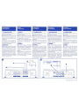
ITALIANO
Collegamenti
degli
ingressi
1)
ALIMENTAZIONE
a)
lnserire sempre il fusibile in
prossimita
della batteria.
b)
Assicurarsi
ehe
il
terminale del
cavo di massa sia saldamente col-
legato ad un punto metallico
della
carrozzeria.
c)
Prelevare "
ON
' per l'accensio-
ne
direttamente dal
"REMO
TE
" del
sintoriproduttore (o preamplifi-
catore o equalizzatore)
2)
SEGNALE
d}
Collegare i jack del cavo di
se-
gnale proveniente dal sintoripr
o-
duttore (o preamplificatore o equa-
lizzatore).
Se
non
dispone di usci-
ta preamplificata interporre un
adattatore di impedenza e
livello.
e)
Regolare
la
sensibilita di ingres-
so
dell'amplificatore con
un
giravite
ruotando
la
vite '
LEVEL"
in
senso
orario (
+)
antiorario (-).
ENG
LI
SH
:
Inputs
'
connections
1)
SUPPLY
a)
Always insert
the
fuse
in
prox-
imity
to
the battery.
b)
Be
sure that the terminal of the
ground cable is firmly connected
to a
meta!
point
in
the
body.
c)
Take "
ON"
for
the
switching
on
directly
from
t
he
"RE
MOTE
" of the
tuner-player (or preamplifier or
equalizer).
2)
SIGNAL
d)
Connect
the
jacks
of
the
signal
cable, coming
from
the
tuner-player
(or preamplifier or equalizer).
lf
there
is
no preamplified output, in-
terpose
an
impedance and level
adaptor.
e)
Ad just the input sensitivity of the
amplifier with a screw-driver, turn-
ing
the
screw '
LEV
EL" clockwise
( +)
or
anti-clockwise
(-).
b l
~r
P--
-----.
@
===>
c:==
===>
c::t:==b
c:I::==>
FRANC:AIS
Connexions
des
entrees
1)
ALIMENTATION
a)
lnserez toujours le fusible a
proximite de
la
batterie.
b)
Assurez-vous que la borne du
cable de masse soit solidement
reliee a
un
point metallique de
la
carrosser
ie.
c)
Prelever
"ON"
pour I' allumage
directem
ent du "REMOTE" du
synto-reproducteur(ou
preampli-
ficateur
ou
egaliseur)
2) SIGNAL
d)
Connecter
les
prises du cable
de
signal provenant du synto-
reproducteur (ou preamplificateur
ou
egaliseur). S'il n'y a pas de sortie
preamplifiee,interposer
un
adapta-
teur
d'
impedance
et
niveau.
e)
Regler
la
sensibilite d' entree de
I'
amplificateur avec
un
tournevis,
en
tournant
la
vis
"LEVEL'
dans
le
se
ns
des aiguilles d' une
montre
( +)
ou
dans
le
sens inverse
(-).
0
J
m]
@
1;~
!!
~)
:
':==_
,=
11
?.
as
===:'
@ [ m t
DEUTSCH
Anschlüsse
der
Eingänge
1)
STROMZUFUHR
a)
Stets
die Sicherung in der Nähe
der Batteire einsetzen.
b)
Überprüfen,
daß
der Masseka-
belschuh fest
an
einer Metallstelle
der
Karosserie
angeschlossen
wird.
c)
"ON"
für
die Zündung direkt
vom
"R
E
MO
TE
" des Wiedergabeyn-
thesizers (oder Vorverstärker oder
Equiliz
er)
nehmen.
2)
SIGNAL
d)
Die Klinkenschal
ter
des Signal-
kabels vom
Wiedergabesyn-
thesizer (oder Vorverstärker oder
Equilizer) anschließen.
Bei
Fehlen
eines vorverstärkten Ausgangs,
einen lmpedanzniveau-Adapter
zwischenschalten.
e)
Die
Eingangsempfindlichkeit
des
Verstärkers
mit
einem
Schrauben-
dr
eher regulieren, indem die
Schraube
'
LEVEL
'
im
(
+)
oder
gegen
den U
hr
zeige
r
sinn
(-)
gedreht
wird.
ESPANOL
Conexion
de
las
entradas
1) ALIMENTACION
a)
Conectar
siempre
el
fusible cerca
de
la
bateria.
b)
Controlar
que
el
terminal
del
cable
de masa
este
fijado
firmemente
a
un
punto metalico del chasis del
vehiculo.
c)
Sacar
el
"ON
"
para
el
encendido,
directamente de
el
"
REMOTE"
del
radioreproductor
(o
preamplificador
o
ecualizador)
.
2) SENAL
d)
Conectar
la
ficha del cable de
sefial proveniente del radiore-
productor (o preamplificador o
ecualizador).
Si
no dispone de
salida
preamplificada, interponer un
adaptador de
im
pedancia y
nivel.
e)
Regular
la
sensibilidad de
entrada
del
autoradio
con
un
des-tornillador,
girando
el
tornillo
"
LEVEL
"
en
sentido
horario
(
+)
antiho
r
ario
(-).
e
HTL 10 2 •
202
•
402
AUDIOSYSTEM 5
-
 1
1
-
 2
2
-
 3
3
-
 4
4
-
 5
5
-
 6
6
-
 7
7
-
 8
8


Audio System HTL 202 Manuale utente
- Categoria
- Amplificatori audio per auto
- Tipo
- Manuale utente
in altre lingue
- English: Audio System HTL 202 User manual
- français: Audio System HTL 202 Manuel utilisateur
- español: Audio System HTL 202 Manual de usuario
- Deutsch: Audio System HTL 202 Benutzerhandbuch
Altri documenti
-
Baumer EAM360-S - SSI Installation and Operating Instructions
-
Baumer EAM360-B - CANopen® Installation and Operating Instructions
-
-
-
-
Balluff BML-S2C0-Q-M6-0-KA-S284 Series Condensed Manual
-
Baumer EIL580-T Installation and Operating Instructions
-
-
Lanzar HTG 237 Manuale utente
-