QK-CE24BATRE
MANUALE D’ISTRUZIONE
INSTRUCTION MANUAL
ISTRUCCIONES DE USO
MANUEL D'INSTRUCTIONS
Apparecchiatura di comando 2 Motori 24Vac
Elettronic control panel for two 24Vac motors
Cuadro electronico para dos motores 24Vac
Carte électronique 2 moteurs 24Vac
ATTENZIONE!!
Prima di effettuare l’installazione, leggere attentamente questo
manuale. La QUIKO declina ogni responsabilità in caso di non osservanza delle
normative vigenti.
WARNING!! Before installing, thoroughly read this manual that is an integral part of this
Kit. QUIKO declines any responsabilità in the event curret stadards in the country of
installation are not comlplied with.
¡ATTENCIÓN!! Antes de efectuar la instalacion, lea attentamente el presente manual.
La Empresa QUIKO no asumirà responsabilidad alguna en caso de inobservancia de las
normas vigentes en el pais donde se lleva a cabo la installacion
ATTENTION!'il vous plaît,attentivement ce manuell'installation. QUIKO décline toute
responsabilitécas de non-conformité à cesèglements.
V01/2018

GENERAL INFORMATION
QK-CE24BATRE
control panel has been designed to control 1 or 2 operators 24 Vdc for
swing gates. It has got an integrated radio receiver. It is also possible to set the
slowing down and anti-crashing features that grant an easy and safe installation.
Safety advises.
In order to prevent any kind of accident, only qualified and professional people will
be allowed to operate, install, repair or ad just the control panel and only after all the
necessary safety rules have been respected, as well as power supply cut off
(including the back up batteries). If the control panel will be used for any other
purpose (not reported in the user manual), will be not responsible for any kind of
damage or accident caused to people, animals or things. This product is not suitable
to be installed in an explosive atmosphere. Keep this booklet together with the rest
of the technical information regarding the installation in a suitable place and
available to professional installer who will need to do future maintenance.
TECHNICAL FEATURES
Absorbed power....................................... 100 mA
Fuse F1.................................................... 20 A
Fuse F2.................................................... 20 A
Time inversion.......................................... 2 sec.fixed
Temperature to work................................. Da –20°C a +50°C
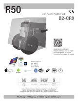
LAY OUT
- +
BATTERY
F1
F2
28 27
OUTPUT
24Vdc
+ -
BLACK RED
12V 7Ah
MAX
- +
1 2 3 4 5 6 7 8
33 34
9 10 11 12 13 14 15 16 17 18 19 20 21 22
AMP
RALL
VELOC
ON
1 2 3 4
ON
1 2 3 4
SW1 SW2
OFF
JUMPER
ON
SW3
EDP
START
STOP
FOTO
FOTO AP
COSTA
P1 P2 P3
DL6
- +
- +
DL7
+ -
12V 7Ah
MAX
ENGLISH

Terminal Description
1-3
PED
Input Pedestrian (N.O. contact); It opens only the leaf of M1.
2-3
START
Input Start (N.O. contact); step by step feature (open-stop-close).
3-4
STOP
Input Stop (N.C. contact) it always stops the motors. If the
contact is used during the pause, it cancels the automatic shutting.
5-7
PHOTO
Input photocells (N.C. contact) working only when gate is
closing (it stops and re-opens).
6-7
PH.OP.
Input photocells working when gates is opening/closing
(N.C. contact). While opening the gate stops and then re-start;
while closing the gate stops and reverses.
7-8
Costa
Input safety edge (N.C. contact) working both in opening/closing.
While opening it stops and reverses for 10cm. While closing it
stops and reverses completely.
9-10
Output 24 Vdc for photocells power supply
(9 negative, 10 positive).
11-12
LOCK
Output 24 Vdc Dip 2 SW2 OFF Electro-lock -
Dip 2 SW2 ON Indicator of gate movement
(11 negative, 12 positive).
13-14
FLASH
Output 24Vdc for the flashing light (13 negative, 14 positive).
15-16
RX Vdc
Out put 24 Vdc for accessories (15 positive, 16 negative).
17-18
M1
Output 24Vdc for Motor 1 (max 3A).
19-20
M2
Output 24Vdc for Motor 2 (max 3A).
21-22
OUT TRASF.
Control panel power supply 24 Vac.
Wire it to the 24Vac output of the toroidal transformer.
27-28
BATTERY
Back up battery input 24V (27 positive, 28 negative).
33-34 Input antenna for onboard receiver (33 coaxial wire, 34 shield).
SW3
Jumper to get an additional feature in terms of powerful; with
jumper, more power - without jumper, less power.
Description of the terminals and wirings.
P.S.: This control panel is delivered with all N.C. outputs wired (stop, safety edge,
photocells, photocells open). If you want to use one of those outputs, cut the wire
and do the connection accordingly.

ON OFF
SW1
1Working with 1 motor. Use input M1..
Working with 2 motors
(M1 + M2).
2Feature “close immediately” enable. When the gate is opening,
as soon as the photocells are disengaged, the gate closes
after 5 seconds.
Feature “close
immediately” disable.
3
First push in an opposite way to release the electro-lock
(for gates with electro-lock only).
Push disable.
4Extra push while starting disable.
Extra push of 2
seconds while starting.
SW2
1
Residential feature enable (while opening the control panel
does not accept any other Start impulse). When gate has
opened, a Start impulse closes the gate without considering
the automatic shutting set on it. Residential feature disable.
Step by step feature enable also during opening.
Residential feature
disable. Step by step
feature enable also
during opening.
2
Enable the indicator of gate movement/position on inputs
10-11 (LOCK).
Enable electro-lock on
inputs 10-11 (LOCK ).
3Enable use of resistive safety edge of 8K2.
Enable use of mechani-
cal safety edge
(N.C. Contact)
4Release Release off
LED description.
PED
It shows the output Pedestrian (normally switched off).
START
It shows the output Start (normally switched off).
STOP
It shows the output Stop (normally switched on).
FOTO
It shows the output Foto
(normally switched on, and if the photocells is engaged it switched off).
FOTO AP
It shows the output Foto AP
(normally switched on, and if the photocells is engaged it switched off).
COSTA
It shows the output safety edge
(normally switched on,B3 and if the safety edge is engaged it switched off).
DL6
It shows the state of the setting.
DL7
Shows the status flash
Close the gate and check that LED stop, foto, foto ap and costa are switched on; otherwise
re-check the wirings.
Trimmer description.
AMP Anti-crashing (obstacle detention) adjustment, when the gate is moving.
RALL.
All adjusted anticlockwise (-) you get an high sensitivity so in case a small
obstacle is on the way, the gate stops. All adjusted clockwise (+) you get a low
sensitivity so in case a small obstacle is on the way, the gate doesn’t stop.
VELOC.
This parameter measures the safety of the gate and it has to be adjusted
according to the local norms.
Dip Switches SW1 & SW2 features.
Fuses description.
F1 - 20A 250V
Output battery protection fuse (27-28). -
F2 - 20A 250V
Transformer output 24Vac protection fuse.
FR1 - 0,65A 250V
Main power supply 230Vac self-repairing protection fuse
(non replaceable)
.
FR2 - 1,6A 250V
Self-repairing protection fuse for photocells, electro-lock, flashing light and accessories
(non replaceable)
.
WARNING: High risk of electric shock ! Cut off the main power supply from the panel before touching the
fuses (F1 and F2). We recommend to re-check the wiring before replacing any fuse

Remote control storing (recommended to be done with the antenna disconnected).
As START button:
Ÿ Close the gate. Press once the button PROGR; led DL6 starts flashing.
Ÿ Press the remote control button you want to store; led DL6 switched off as
confirmation that code has been stored.
You can store up to max. 32 different codes for the Start.
As Pedestrian button:
Ÿ Close the gate. Press twice the button PROGR; led DL6 starts flashing.
Ÿ Press the remote control button you want to store; led DL6 switched off as
confirmation that code has been stored.
You can store up to max. 32 different codes for the Pedestrian.
Remote control cancellation.
Cancellation of a single code stored into START or PEDESTRIAN:
Ÿ Press at the same time both buttons PROGR and PAUSA; led DL6 starts flashing
quickly.
Ÿ Within 10 sec. press remote control button you want to cancel; led DL6 switches
off to confirm the cancellation.
Cancellation of all codes stored into the control panel:
Press at the same time both buttons PROGR and PAUSA for about 10 seconds.
Led DL6 starts flashing quickly and after 10 seconds will switch off confirming the
cancellation has been done.
Preliminary checks before setting the control panel.
Ÿ Power the control panel and verify that LED Stop, Foto, Foto AP and Costa are
on; if this doesn’t correspond, re-check the wirings and or safety devices state.
Any NC contact not used, has to be wired/closed.
Ÿ Verify that all safety devices installed in the gate are working properly in order to
reduce any possible accident.
Ÿ Verify the correct wirings, keeping in mind that 1st START impulse has to open the
gate, otherwise, just swap the wires 17-18 for M1 and/or 19-20 for M2.
Automatic setting of the stroke with leaves delay and slowing down spaces fix.
Following instruction are for a 2 leaves swing gate; in case of 1 single swing leaf
(dip 1 SW1 ON) the instruction regards only the motor M1.
Ÿ Place the leaves half way opening; keep pressed the button PROGR. until both
operators will start closing (approx. 10 seconds).
Ÿ The control panel closes the leaves until they touch the mechanical stoppers.
Ÿ M1 starts opening and after 3 seconds M2 starts opening too.
Ÿ Both operators will stop automatically at the mechanical stoppers in opening.
Ÿ Then, the control panel will close the leaves finishing with a slowing down before
touching the mechanical stoppers in closing.
Ÿ The control panel automatically goes out from the setting and it is ready to work.
In the automatic setting, the delay between the 2 leaves is 3 seconds both in
opening and closing and the slowing down is approx. 4 seconds before reaching the
mechanical stoppers.
WARNING: In case of re-adjustment of the trimmer RALL. or VELOC. it is
ABSOLUTELY necessary to repeat the setting.

Manual setting of the stroke with leaves delay and slowing down spaces
customized.
Following instruction are for a 2 leaves swing gate; in case of 1 single swing leaf
(dip 1 SW1 ON) the instruction regards only the motor M1.
Ÿ Close the gate and press once button PROGR.; led DL6 starts flashing.
Ÿ Press once button LAVORO; M1 leaf starts opening.
Ÿ As soon as M1 leaf has reached the position you want to set the slowing down,
press again the button LAVORO, the leaf will start the slowing down procedure.
If you don’t want any slowing down, then ignore this topic and go further.
Ÿ After that, M1 leaf will hit the mechanical stopper in opening and automatically will
stop.
Ÿ Press again button LAVORO to start counting the delay of the leaves in opening;
Led DL6 flashes fast.
Ÿ Press again button LAVORO to stop the counting for the time to apply to the delay
in opening. Automatically M2 leaf starts opening.
Ÿ When M2 leaf has reached the position you want to set the slowing down, press
again button LAVORO, the leaf will start the slowing down procedure. If you don’t
want any slowing down, then ignore this topic and go further.
Ÿ After that, M2 leaf will hit the mechanical stopper in opening and automatically will
stop.
Ÿ Press once again the button LAVORO. Leaf with M2 starts closing.
Ÿ When M2 leaf has reached the position you want to set the slowing down in clos-
ing, then press button LAVORO and the leaf will start the slowing down procedure.
If you don’t want any slowing down, then ignore this topic and go further.
Ÿ After that, M2 leaf will hit the mechanical stopper in closing and automatically will
stop.
Ÿ Press remote button LAVORO to start counting the delay of the leaves in closing
(Led DL6 starts flashing quickly).
Ÿ Press again button LAVORO to stop the counting for the time to apply to the delay
in closing. Automatically M1 leaf starts closing.
Ÿ When M1 leaf has reached the position you want to set the slowing down in
closing, then press button LAVORO and the leaf will start the slowing down
procedure. If you don’t want any slowing down, then ignore this topic and go
further.
Ÿ After that, M1 leaf will hit the mechanical stopper in closing and automatically will
stop.
Ÿ When the closing has finished, the control panel will automatically go out from the
programming and it will be ready to work.
WARNING: In case of re-adjustment of the trimmer RALL. or VELOC. it is
ABSOLUTELY necessary to repeat the setting.

Manual setting of the stroke using a remote control.
Store the remote control to the START (see page 5).
Close the gate and press once both buttons PROGR. and LAVORO; led DL6
starts flashing quickly.
Hereinafter follow up the setting as reported (see page 6) pressing remote control
button just stored instead of LAVORO button.
Setting of the automatic shutting time.
Close the gate and press once button PROGR.; led DL6 starts flashing.
Press once the button PAUSA; led DL6 starts flashing quickly, the control panel is
counting the automatic shutting time.
To stop the counting, press again the button PAUSA; led DL6 switches off.
Maximum time to set is 120 seconds.
To disable the automatic shutting:
Press once the button PROGR..
Press quickly twice (2 times) button PAUSA
How to get separate inputs OPEN-CLOSE.
How to turn START into CLOSE only:
Cut off power supply, keep pressed both buttons PROGR. and PAUSA and give
power back keeping the buttons pressed down; led DL6 flashes to confirm the good
success of the operation, now release the buttons.
How to turn PED into OPEN only:
Cut off power supply, keep pressed both buttons PROGR. , LAVORO and PAUSA
and give power back keeping the buttons pressed down; led DL6 flashes to confirm
the good success of the operation, now release the buttons.
How to go back to START and PED as sequential/standard inputs:
To get START back, cut off power supply, keep pressed both buttons PROGR. and
LAVORO and give power back keeping the buttons pressed down; led DL6 flashes
to confirm the good success of the operation, now release the buttons.
To get PED back, cut off power supply, keep pressed both buttons PROGR. And
LAVORO and give power back keeping the buttons pressed down; led DL6 flashes
to confirm the good success of the operation, now release the buttons.
P.S.: The control panel is delivered from the factory with inputs START and
PED as sequential/standard inputs.
Additional important information.
This control panel con work with or without back up battery. In any case, it uploads and keeps
leaded the back up battery at the same time; approx. 24h are necessary to re-charge the battery
for completely. In case the control panel works only with the back up battery, the photocells
start working only in presence of a START signal; moreover, if a flashing light or a door indicator
are wired on the panel, the frequency of the blinks will slow down to save energy.
If the back up battery has almost run out, the control panel remains powered but when the bat-
tery runs out completely, the panel doesn’t accept the START signal; the panel needs 140 mA
as normal working that is equivalent to 50 hours working with a back up battery of 7Ah and in
Stand-By 38 mA that is equivalent to 184 hours with a back up battery of 7Ah.
This control panel is provided with an anti crashing system that recognises the obstacles. This
feature can be adjusted by the Trimmer AMP. When the gate meets an obstacle while opening,
it stops and reverses the stroke for about 1 sec. and after 30 sec. it closes automatically. When
the gate meets an obstacle while closing, it stops and re-open completely.
In case the automatic shutting is enable and the gate hits an obstacle, the control panel will try
to close the gate for max. 3 times then the gate will remain open, waiting for a START signal in
order to close.

GENERALITA’:
La centrale QK-CE24BATRE è progettata per comandare uno o due motori a 24 Vdc
per cancello ad ante. E’ dotata di rallentamenti, rilevazione ostacolo, scheda radio
incorporata e funzione di auto-programmazione che permette installazioni semplici
e sicure.
Norme di sicurezza generale:
E’ vietata ogni operazione di montaggio, riparazione o regolazione
dell'apparecchiatura da parte di personale non qualificato e qualora non siano state
prese tutte le precauzioni necessarie per evitare possibili incidenti: alimentazione
elettrica disinserita (comprese eventuali batterie tampone). Qualsiasi utilizzo non
previsto da questo libretto istruzioni e/o ogni modifica arbitraria apportata a questo
prodotto o ai suoi componenti, solleva da ogni responsabilità derivante da
conseguenti danni o lesioni a cose, persone o animali. Conservare
scrupolosamente il presente manuale allegandolo al fascicolo tecnico
dell’installazione in un luogo idoneo e noto a tutti gli interessati al fine di renderlo
disponibile in futuro.
CARATTERISTICHE TECNICHE
Potenza assorbita a riposo........................... 100 mA
Fusibile F1.................................................... 20 A
Fusibile F2.................................................... 20 A
Tempo di inversione...................................... 2 secondi fissi
Temperatura di esercizio............................... Da –20°C a +50°C
LAY OUT CENTRALINA
ITALIANO
- +
1 2 3 4 5 6 7 8
33 34
9 10 11 12 13 14 15 16 17 18 19 20 21 22
AMP
RALL
VELOC
ON
1 2 3 4
ON
1 2 3 4
SW1 SW2
OFF
JUMPER
ON
SW3
P DE
TRATS
POTS
OTOF
PA OTOF
ATSOC
P1 P2 P3
DL6
- +
- +
DL7
+ -
NERO ROSSO
12V 7Ah
MAX
- +
BATTERY
F1
F2
28 27
USCITA
24Vdc
+ -
12V 7Ah
MAX

1-3
PED
Pulsante Pedonale (contatto N.A.); Apre solo l'anta M1
2-3
START
Pulsante Start (contatto N.A.); funzione sequenziale apre, stop,
chiude.
3-4
STOP
Pulsante stop (contatto N.C.); ferma sempre i motori, se premuto
durante il tempo di pausa annulla la richiusura automatica.
5-7
PHOTO
Ingresso fotocellula (contatto N.C.) attiva solo in chiusura;
ferma e riapre.
6-7
PH.OP.
Ingresso fotocellula sempre attiva (contatto N.C.);
in apertura ferma e riparte, in chiusura ferma e inverte.
7-8
Costa
Ingresso Costa di sicurezza sempre attiva (contatto N.C.);
in apertura ferma e inverte 10 cm;
in chiusura ferma e inverte tutta la corsa.
9-10
Uscita 24Vdc per alimentazione fotocellule
(9 negativo e 10 positivo).
11-12
LOCK
Uscita 24Vdc per Elettroserratura o Spia cancello aperto
(11 negativo e 12 positivo).
13-14
FLASH
Uscita 24Vdc per alimentazione del lampeggiante
(13 negativo e 14 positivo).
15-16
RX Vdc
Uscita 24Vdc per alimentazione acessori
(15 positivo e 16 negativo).
17-18
M1
Uscita 24Vdc per Motore 1 (max 3A).
19-20
M2
Uscita 24Vdc per Motore 2 (max 3A).
21-22
OUT TRASF.
Ingresso alimentazione centralina 24Vac;
collegare l’uscita 24Vac del trasformatore toroidale.
27-28
BATTERY
Collegamento batteria tampone 24V (27 positivo e 28 negativo).
33-34
Ingresso antenna per ricevitore incorporato
(33 polo caldo e 34 calza).
SW3
Jumper per ulteriore regolazione della forza motori;
aperto più forza e chiuso meno forza.
Descrizione collegamenti elettrici.
N.B.: La centrale viene fornita con contatti normalmente chiusi ponticellati (stop,
costa, fotocellula, fotocellula apre). Se si vuole utilizzare uno di questi ingressi,
togliere il ponte dell’ingresso desiderato ed eseguire il collegamento elettrico.

ON OFF
SW1
1
Funzionamento a un motore (usare solo M1).
Funzionamento a due motori (M1 + M2).
2Con cancello aperto, al disimpegno della
fotocellula, il cancello chiude
automaticamente dopo 5 secondi.
Il cancello non richiude automaticamente
o, se impostata, rispetta il tempo di
richiusura automatica programmato.
3Colpo d’ariete attivato (per cancelli con
elettroserratura).
Colpo d’ariete disattivato.
4Spunto alla partenza disattivato. Spunto di 2 secondi alla partenza.
SW2
1
Funzione condominiale; la centrale ignora
il comando di start durante l’apertura.
La centrale accetta il comando di start sia
durante l’apertura che la chiusura.
2Morsetto 11-12 in funzionamento
Spia cancello aperto.
Morsetto 11-12 in funzionamento
elettroserratura.
3Costa di sicurezza di tipo resistivo 8K2 ohm Costa di sicurezza di tipo meccanico con
contatto N.C..
4
Colpo di inversione attivato (rilascio motore)
Colpo di inversione disattivato
Descrizione led presenti sulla scheda.
PED
Visualizza lo stato dell’ingresso Pedonale (normalmente spento).
START
Visualizza lo stato dell’ingresso Start (normalmente spento).
STOP
Visualizza lo stato dell’ingresso Stop (normalmente acceso).
FOTO
Visualizza lo stato dell’ingresso Foto
(normalmente acceso, spento su intervento della fotocellula).
FOTO AP
Visualizza lo stato dell’ingresso Foto AP
(normalmente acceso, spento su intervento della fotocellula)
COSTA
Visualizza lo stato dell’ingresso Costa
(normalmente acceso, spento su intervento della costa meccanica).
DL6
Visualizza lo stato della programmazione.
DL7
Visualizza lo stato del lampeggiatore
A cancello chiuso verificare che i led STOP, FOTO, FOTO AP e COSTA siano accesi; altrimenti
controllare i collegamenti.
Descrizione dei trimmer.
AMP
Regolazione della sensibilità del rilevamento ostacolo durante il movimento del
cancello.
Tutto in senso antiorario (-) si ha un’alta sensibilità all’ostacolo;
tutto in senso orario (+) si ha una bassa sensibilità all’ostacolo.
Questo parametro determina il livello di sicurezza dell’automazione.
RALL.
Regolazione della velocità del motore durante il rallentamento;
senso antiorario (-) minima velocità, senso orario (+) esclusione del
rallentamento.
VELOC.
Regolazione della velocità del motore durante durante la corsa;
senso antiorario (-) minima velocità, senso orario (+) massima velocità.
Funzioni programmabili tramite dip switch SW1 e SW2.
Leggenda fusibili a bordo scheda.
F1 - 20A 250V Fusibile di protezione per l’uscita batteria (morsetto 27 e 28).
F2 - 20A 250V Fusibile di protezione per l’uscita 24Vac del trasformatore.
FR1 - 0,65A 250V Fusibile di protezione autoripristinante per alimentazione 230Vac (non sostituibile).
FR2 - 1,6A 250V Fusibile di protezione autoripristinante per fotocellule, elettroserratura, lampeggiante e
accessori (non sostituibile).
Attenzione: rischio di folgorazione! Togliere alimentazione alla centrale prima di sfilare i fusibili (F1 e F2).
Si consiglia di controllare i cablaggi prima di sostituire il fusibile bruciato.

Apprendimento dei radiocomandi
(si consiglia di eseguirlo con l’antenna non collegata).
Associati al comando START:
Ÿ Con cancello chiuso, premere e rilasciare il tasto PROGR; il led DL6 inizia a
lampeggiare.
Ÿ Premere il tasto del radiocomando; il led DL6 si spegne a conferma della
memorizzazione.
Si possono memorizzare un massimo di 32 diversi codici per il comando Start.
Associati al comando Pedonale:
Ÿ Con il cancello chiuso premere e rilasciare due volte il tasto PROGR; il led DL6
inizia a lampeggiare.
Ÿ Premere il tasto del radiocomando; il led DL6 si spegne a conferma della
memorizzazione.
Si possono memorizzare un massimo di 32 diversi codici per il comando Pedonale.
Cancellazione telecomandi.
Cancellazione di un singolo codice associato allo START o al PEDONALE:
Ÿ Premere contemporaneamente e rilasciare i tasti PROGR e PAUSA; il led DL6
lampeggia velocemente.
Premere il tasto del radiocomando da cancellare entro 10 sec.; il led DL6 si spegne
a conferma della cancellazione.
Cancellazione totale dei radiocomandi memorizzati nella centrale:
Premere contemporaneamente e tenere premuti i tasti PROGR e PAUSA per circa
10 secondi. Il led DL6 inizierà a lampeggiare velocemente e dopo 10 sec. si
spegnerà a conferma della totale cancellazione.
Verifiche preliminari prima della programmazione della corsa.
Ÿ Alimentare la centralina e controllare che i led Stop, Foto, Foto AP e Costa siano
accesi; se non corrisponde controllare il cablaggio di pulsanti e dispositivi di
sicurezza, i contatti N.C. non utilizzati vanno ponticellati.
Ÿ Verificare il corretto funzionamento di tutti i dispositivi di sicurezza installati al fine
di ridurre al minimo ogni eventuale rischio.
Ÿ Verificare il corretto collegamento dei motori tenendo presente che la prima
manovra che la centrale esegue è un'apertura.
Programmazione automatica della corsa con tempi di sfasamento
e
rallentamento fissi.
Descrizione per cancello a due ante; in caso di anta singola (dip 1 SW1 ON) le fasi
interessano solo il motore M1.
Ÿ Premere e mantenere premuto il pulsante PROGR. fino alla partenza dei motori
(circa 10 secondi).
Ÿ La centrale porta automaticamente entrambe le ante in posizione di completa
chiusura fermandosi sui fermi meccanici.
Ÿ L'anta M1 inizia l’apertura e dopo 3 secondi parte anche l'anta M2.
Ÿ Raggiunti i fermi meccanici in apertura entrambi i motori si fermano
automaticamente.
Ÿ La centrale esegue il ciclo di chiusura terminando in rallentamento per poi fermarsi
correttamente sui fermi meccanici.
Ÿ La centrale esce automaticamente dalla fase di programmazione e s’imposta per il
funzionamento normale.
Nella programmazione automatica lo sfasamento tra le due ante è impostato a 3 secondi
fissi sia in apertura che in chiusura e il rallentamento è di circa 4 secondi fissi prima dei
fermi meccanici.
ATTENZIONE: Nel caso di regolazione dei trimmer RALL. O VELOC. è necessario ripetere
l’autoprogrammazione.

Programmazione manuale della corsa con tempi di sfasamento e
rallentamento personalizzati.
Descrizione per cancello a due ante; in caso di anta singola (dip 1 SW1 ON) seguire
solo i punti del motore M1.
Ÿ A cancello chiuso premere e rilasciare il pulsante PROGR.; il led DL6 lampeggia.
Ÿ Premere e rilasciare il tasto LAVORO; L'anta M1 parte in apertura.
Ÿ Raggiunto il punto di rallentamento desiderato premere e rilasciare il tasto
LAVORO, l'anta M1 rallenta; se non si desidera il rallentamento ignora questo
passaggio e prosegui.
Ÿ Raggiunto il fermo meccanico di massima apertura il motore M1 si ferma
automaticamente.
Ÿ Premere e rilasciare LAVORO; inizia il conteggio del tempo di sfasamento in
apertura (il led DL6 lampeggia velocemente).
Ÿ Trascorso il tempo di sfasamento desiderato premere e rilasciare LAVORO; l'anta
M2 inizia l’apertura.
Ÿ Raggiunto il punto di rallentamento desiderato premere e rilasciare il tasto
LAVORO, l'anta M2 rallenta; se non si desidera il rallentamento ignora questo
passaggio e prosegui.
Ÿ Raggiunto il fermo meccanico di massima apertura il motore M2 si ferma
automaticamente.
Ÿ Premere e rilasciare il tasto LAVORO; l'anta M2 parte in chiusura.
Ÿ Raggiunto il punto di rallentamento desiderato premere e rilasciare il tasto
LAVORO, l'anta M2 rallenta; se non si desidera il rallentamento ignora questo
passaggio e prosegui.
Ÿ Raggiunto il fermo meccanico di massima chiusura il motore M2 si ferma
automaticamente.
Ÿ Premere e rilasciare LAVORO; inizia il conteggio del tempo di sfasamento in
chiusura (il led DL6 lampeggia velocemente).
Ÿ Trascorso il tempo di sfasamento desiderato premere e rilasciare LAVORO; l'anta
M1 inizia la chiusura.
Ÿ Raggiunto il punto di rallentamento desiderato premere e rilasciare il tasto
LAVORO, l'anta M1 rallenta; se non si desidera il rallentamento ignora questo
passaggio e prosegui.
Ÿ Raggiunto il fermo meccanico di massima chiusura il motore M1 si ferma
automaticamente.
Ÿ Programmazione conclusa; la centrale esce automaticamente dalla
programmazione e s’imposta per il normale funzionamento.
ATTENZIONE: Nel caso di regolazione dei trimmer RALL. O VELOC. è necessario
ripetere la programmazione.

Programmazione della corsa da radiocomando.
Ÿ Memorizzare un radiocomando associato al comando Start; vedi PAG 5.
Ÿ A cancello chiuso premere contemporaneamente e rilasciare i pulsanti PROGR. e
LAVORO; il led DL6 lampeggia velocemente.
Ÿ Da qui in poi seguire la procedura di Programmazione a PAG 6, sostituendo il
tasto LAVORO con il tasto del radiocomando appena memorizzato.
Programmazione del tempo di richiusura automatica.
Ÿ A cancello chiuso premere e rilasciare il pulsante PROGR.; il led DL6 lampeggia.
Ÿ Premere e rilasciare il pulsante PAUSA; il led DL6 lampeggia velocemente
indicando che la centrale sta conteggiando il tempo.
Ÿ Premere e rilasciare il pulsante PAUSA; termina il conteggio e il led DL6 si spegne.
Il tempo massimo programmabile è di 120 secondi.
Per disattivare la chiusura automatica:
Ÿ Premere e rilasciare il pulsante PROGR..
Ÿ Premere e rilasciare il pulsante PAUSA due volte velocemente.
Impostazione del funzionamento a pulsanti separati.
Per impostare l’ingresso START come ingresso per comandare solo la chiusura:
Togliere l’alimentazione alla centrale, premere e mantenere premuti i tasti PROGR.
e PAUSA e ridare alimentazione mantenendoli premuti; il led DL6 lampeggia per
confermare il funzionamento, quindi rilasciare i tasti.
Per impostare l’ingresso PED come ingresso per comandare solo l’apertura:
Togliere l’alimentazione alla centrale, premere e mantenere premuti i tasti PROGR.,
PAUSA e LAVORO e ridare alimentazione mantenendoli premuti; il led DL6
lampeggia per confermare il funzionamento, quindi rilasciare i tasti.
Ripristino degli ingressi START e PED su sequenziali/standard:
Per ripristinare l’ingresso START togliere l’alimentazione alla centrale, premere e
mantenere premuti i tasti PROGR. e LAVORO e ridare alimentazione mantenendoli
premuti; il led DL6 lampeggia per confermare il funzionamento, quindi rilasciare i tasti.
Per ripristinare l’ingresso PED togliere l’alimentazione alla centrale, premere e
mantenere premuti i tasti LAVORO e PAUSA e ridare alimentazione mantenendoli
premuti; il led DL6 lampeggia per confermare il funzionamento, quindi rilasciare i tasti.
N.B.: di default la centrale viene fornita con la configurazione START e PED come
ingressi di comando SEQUENZIALI/STANDARD.
Nota bene.
Ÿ La centrale può funzionare con o senza batteria e provvede sia alla ricarica che al
mantenimento della stessa; sono necessarie circa 24 ore per una completa ricarica. Nel
caso di alimentazione con solo batteria la centrale toglie l'alimentazione delle fotocellule
e viene riattivata solo in caso di Start; diminuisce inoltre la frequenza di lampeggio del
lampeggiante e della spia nel caso siano collegati. Se la batteria è quasi scarica la
centrale resta alimentata fino a batteria esausta ma non prende il comando Start; gli
assorbimenti in normale funzionamento sono di 140 mA pari a 50 ore con batteria da
7Ah e in Stand-By 38 mA pari a 184 ore con batteria da 7Ah.
Ÿ Questa centrale è dotata di sistema rilevazione ostacolo regolabile tramite il trimmer
AMP; in caso di ostacolo in apertura il cancello si ferma e inverte per circa 1 secondo per
poi richiudersi automaticamente dopo 30 secondi; in caso di ostacolo in chiusura il
cancello si ferma e riapre totalmente. Nel caso la chiusura automatica sia attiva e
interviene la rilevazione ostacoli, la centrale esegue un massimo di 3 tentativi di chiusura,
dopo di che il cancello resta fermo aperto in attesa di un comando di Start.

GENERALIDAD:
El cuadro de maniobra
QK-CE24BATRE
ha sido diseñado para mandar uno o dos
motores a 24 Vdc para puertas batiente. Tiene función de auto-programación,
disminución de velocidad, detectión con obstaculo y un receptor incorporado para
ser instalado y programado muy facilmente.
Normas de seguridad generales.
Se prohíbe cualquier operación de montaje, reparación o regulación de los equipos
por parte de personal no capacitado y en caso de que no se hayan aplicado todas
las precauciones necesarias para evitar los posibles accidentes. Se debe
desconectar la alimentación eléctrica (incluyendo las posibles baterías tampones).
Cualquier uso no previsto en el presente manual de instrucciones y/o cualquier
modificación arbitraria realizada en este producto o en sus componentes, libera de
cualquier responsabilidad que derive de los daños o lesiones consiguientes a cosas,
personas o animales. Este producto no es apto para ser instalado en una atmósfera
explosiva. Conservar escrupulosamente el presente manual adjuntándolo al
fascículo técnico de la instalación en un lugar idóneo y conocido a todos los
interesados, con el fin de volverlo disponible en el futuro.
CARACTERÍSTICAS TÉCNICAS
Corriente absorbida..................................... 100 mA
Fusible F1.................................................... 20 A
Fusible F2.................................................... 20 A
Tiempo de inversión...................................... 2 secondi fissi
Temperatura trabajo..................................... Da –20°C a +50°C
LAY OUT
ESPAÑOL
- +
1 2 3 4 5 6 7 8
- +
BATTERY
33 34
9 10 11 12 13 14 15 16 17 18 19 20 21 22
F1
F2
AMP
RALL
VELOC
ON
1 2 3 4
ON
1 2 3 4
SW1 SW2
OFF
JUMPER
ON
SW3
P DE
TRATS
POTS
OTOF
PA OTOF
ATSOC
P1 P2 P3
DL6
28 27
- +
- +
DL7
USCITA
24Vdc
+ -
+ -
NEGRO ROJO
12V 7Ah
MAX12V 7Ah
MAX

1-3
PED
Peatonal (input N.A.); Abre solo la hoja M1.
2-3
START
Start (input N.A.); función sequencial abre, stop, cierra.
3-4
STOP
Stop (input N.A.); para los motores. Si se actua durante el tempo
de pausa, cancela el cierre automático.
5-7
PHOTO
Fotocélulas (input N.C.) función activa solo en cierre; para y
vuelve abrir.
6-7
PH.OP.
Fotocélula abre siempre activa (input N.C.);
en apertura para y vuelve abrir, en cierre para e invierte.
7-8
Costa
Borde de seguridad, sempre activo (input N.C.);
en apertura para e invierte de 10cm;
en cierre para e invierte por toda la carrera.
9-10
Output 24Vdc alimentación de las fotocélulas
(9 negativo y 10 positivo).
11-12
LOCK
Output 24Vdc Electrocerradura o Indicación del estado del portón
(11 negativo y 12 positivo).
13-14
FLASH
Output 24Vdc alimentación lámpara destellante
(13 negativo y 14 positivo).
15-16
RX Vdc
Output 24Vdc alimentación de los accesorios
(15 positivo y 16 negativo).
17-18
M1
Output 24Vdc Motor 1 (max 3A).
19-20
M2
Output 24Vdc Motor 2 (max 3A).
21-22
OUT TRASF.
Input alimentación del cuadro de maniobra 24Vac;
conectar la salida 24Vac del transformador toroidal.
27-28
BATTERY
Conexión batería de respaldo 24V (27 positivo y 28 negativo).
33-34
Input antena del receptor incorporado
(33 polo caliente y 34 malla).
SW3
Jumper para un ajuste adicional del par de los motores; abierto,
mas fuerza y cerrado, menos fuerza.
Descriptión de las conexiones eléctricas.
N.B.: El cuadro de maniobra se entrega normalmente con los inputs NC
(Normalmente Cerrado) ya cablados (stop, borde de seguridad, fotocélulas,
fotocélulas abre). Si se necesita usar unos de estos inputs, quitar el puente y
conectar el dispositivo según su instrucciones.

ON OFF
SW1
1Funcionamiento a un motor (usar solo M1)..
Funcionamiento a dos motores (M1 + M2).
2
Con la puerta en apertura o abierta, una véz
que las fotocélulas esten libre, la puerta
cierra automáticamente después de 5
segundos.
La puerta cierra automáticamente solo si
el cierre automático está programado.
3Empuje inicial opuesto a la carrera, activado
(para puertas con electrocerradura).
Empuje inicial opuesto a la carrera,
desactivado
4Empuje de arranque desactivado. Empuje de arranque de 2 segundos.
SW2
1Función residencial; el cuadro ignora el
mando de Start durante la apertura.
El cuadro acepta el mando de Start
durante la apertura y el cierre.
2Bornes 11-12 funciona como indicador del
estado de la puerta.
Bornes 11-12 funciona como
electrocerradura.
3Borde de seguridad de tipo resistivo 8K2
ohm.
Borde de seguridad de tipo mecánico con
contacto N.C..
4Liberación de motor Liberación de motor off
PED Muestra el estado del input Peatonal (normalmente apagado).
START
Muestra el estado del input Start (normalmente apagado).
STOP Muestra el estado del input Stop (normalmente prendido).
FOTO Muestra el estado del input Foto
(normalmente prendido. Se apaga al activarse las fotocélulas).
FOTO AP Muestra el estado del input Foto Ap
(normalmente prendido. Se apaga al activarse las fotocélulas)
COSTA Muestra el estado del input Borde de seguridad
(normalmente prendido. Se apaga al activarse el Borde).
DL6 Muestra el estado de la Programación.
DL7 Muestra lo estado de la lampara de destellos
Con la puerta cerrada, verificar que los indicadores luminosos stop, foto, foto ap y borde de
seguridad sean prendidos; si no, chequear las conexiones.
Descripción de los trimmer.
AMP Regulación de la sensibilidad en detectar un obstaculo, durante el movimiento
de la puerta. Puesto todo en sentido opuesto a él de las agujas del reloj (-) hay
una sensibilidad alta; Puesto todo en sentido a él de las agujas del reloj (+) hay
una sensibilidad baja. Esta regulación, determina el nivel de seguridad del
automatismo instalado.
RALL.
Regulación de la velocidad del motor durante la disminución de velocidad; en el
sentido opuesto a él de las agujas del reloj (-) hay una velocidad minima; en el
sentido a él de las agujas del reloj (+) se pone en cero la disminución de
velocidad.
VELOC.
Regulación de la velocidad del motor durante la carrera; en el sentido opuesto a
él de las agujas del reloj (-) hay una velocidad minima; en el sentido a él de las
agujas del reloj (+) hay una velocidad maxima.
Funciones programables a través de los dip switch SW1 y SW2.
F1 - 20A 250V Fusible de protección para la batería de respaldo (borne 27 y 28).
F2 - 20A 250V Fusible de protección output 24Vac del transformador.
FR1 - 0,65A 250V Fusible de protección autoreparante (no reemplazable) para la alimentación 230Vac.
FR2 - 1,6A 250V Fusible de protección autoreparante (no reemplazable) para las fotocélulas, las
electrocerratura, la lampara y los accesorios.
Ciudado: riesgo de electrocución!! Quitar la corriente del cuadro antes de mover los fusibles (F1 y F2).
Se aconseja de chequear los cablajes antes de reemplazar los fusibles.
Descriptión de los indicadores luminosos.
Descriptión de los fusibles.

Memorización de los mandos a distancia (se aconseja de desconectar la antena).
Asociado al mando START:
Ÿ
Cerrar la puerta. Oprimir
una véz
el botón PROGR; el led DL6 comienza a parpadear.
Ÿ Oprimir el botón del mando a distancia que se quiere memorizar; el led DL6 se
apaga para confirmar la memorización.
Se pueden memorizar un maximo de 32 codigos diferentes en el mando de Start.
Asociado al mando Peatonal:
Ÿ
Cerrar la puerta. Oprimir
dos veces
el botón PROGR; el led DL6 comienza a parpadear.
Ÿ Oprimir el botón del mando a distancia que se quiere memorizar; el led DL6 se
apaga para confirmar la memorización.
Se pueden memorizar un maximo de 32 codigos diferentes en el mando de Start.
Cancelación de los mandos a distancia memorizados.
Cancelación de un solo codigo associado al START o al PEATONAL:
Ÿ Oprimir contemporaneamente y liberar los botones PROGR y PAUSA; el led DL6
parpadea rapidamente.
Ÿ Entre 10 seg., oprimir el botón del mando a distancia que se quiere cancelar; el
led DL6 se apaga a confirmación de la cancelación.
Cancelación total de todos los codigos de los mandos a distancia memorizados
en el cuadro:
Oprimir contemporaneamente por 10 segundos los botones PROGR y PAUSA; el
led DL6 parpadea rapidamente y después de 10 segundos se apagará a
confirmación que todos los codigos han sido cancelados.
Chequeos preliminares antes de programar la carrera de las hojas.
Ÿ Alimentar el cuadro y verificar que los led Stop, Foto, Foto AP y Borde sean
prendidos, si no, chequear las conexiones de los dispositivos de seguridad. Los
input NC no utilizado, hay que cerrarlos con un “puente”.
Ÿ Verificar que los dispositivos de seguridad funcionen correctamente para reducir
al minimo los riesgos.
ŸVerificar que la primera maniobra de los motores con el mando Start, sea una
apertura; si no invertir los cables 17-18 del motor 1 o 19-20 del motor 2.
Programación automática de la carrera con los tiempos de retrazo entre las
hojas y disminución de velocidad fijos.
Descriptión para puerta con dos hojas; en caso de una sola hoja (dip 1 SW1 en ON)
y usar el motor M1.
Ÿ Mantener oprimido el botón PROGR. hasta que los motores arranquen
(aprox. 10 segundos).
Ÿ El cuadro lleva automáticamente ambas hojas en posición de cierre completo
parandose en los topes mecánicos.
Ÿ La hoja del motor M1 arranca en apertura y después de 3 segundos, arranca
también la hoja del motor M2.
Ÿ Una véz alcanzado los topes mecánicos en apertura, ambos motores se paran
automáticamente.
Ÿ El cuadro termina la programación con el cierre disminuyendo la velocidad y
parandose en los topes mecánicos.
Ÿ Una véz que las hojas estan cerrada, el cuadro automáticamente sale de la
programación y esta listo para funcionar normalmente.
En la programación automática el retrazo entre las hojas es fijo de 3 segundos sea
en apertura que en cierre y la disminución de velocidad es de aprox. 4 segundos
antes de los topes mecánicos.
CUIDADO: En el caso de regulación de los trimmer RALL. O VELOC. es necesario
repetir la Programación.

Programación manual de la carrera con los tiempos de retrazo entre las hojas
y disminución de velocidad programables.
Descriptión para puerta con dos hojas; en caso de una sola hoja (dip 1 SW1 en ON)
y usar el motor M1.
Ÿ Cerrar la puerta. Oprimir una véz el botón PROGR.; el led DL6 parpadea.
Ÿ Oprimir una véz el botón LAVORO; la hoja M1 arranca en apertura.
Ÿ Cuando la hoja alcanza el punto de disminución deseado, oprimir otra véz el
botón LAVORO, la hoja del M1 disminuye la velocidad; si no se quiere la
disminución de velocidad, ignorar este pasaje y seguir.
Ÿ Una véz alcanzado el tope mecánico de maxima apertura, el motor M1 se para
automáticamente.
Ÿ Oprimir una véz el botón LAVORO; comienza el contar del tempo de retrazo de
las hojas en apertura (el led DL6 parpadea rapidamente).
Ÿ Para parar el contar del tiempo de retrazo entre las hojas, oprimir otra véz el
botón LAVORO; la hoja M2 arranca en apertura.
Ÿ Cuando la hoja alcanza el punto de disminución deseado, oprimir otra véz el
botón LAVORO, la hoja del M2 disminuye la velocidad; si no se quiere la
disminución de velocidad, ignorar este pasaje y seguir.
Ÿ Una véz alcanzado el tope mecánico de maxima apertura, el motor M2 se para
automáticamente.
Ÿ Oprimir una véz el botón LAVORO; la hoja M2 arranca en cierre.
Ÿ Cuando la hoja alcanza el punto de disminución deseado, oprimir otra véz el
botón LAVORO, la hoja del M2 disminuye la velocidad; si no se quiere la
disminución de velocidad, ignorar este pasaje y seguir.
Ÿ Una véz alcanzado el tope mecánico de cierre, el motor M2 se para
automáticamente.
Ÿ Oprimir una véz el botón LAVORO; comienza el contar del tiempo de retrazo de
las hojas en cierre (el led DL6 parpadea rapidamente).
Ÿ Para parar el contar del tiempo de retrazo entre las hojas, oprimir otra véz el
botón LAVORO; la hoja M1 arranca en cierre.
Ÿ Cuando la hoja alcanza el punto de disminución deseado, oprimir otra véz el
botón LAVORO, la hoja del M1 disminuye la velocidad; si no se quiere la
disminución de velocidad, ignorar este pasaje y seguir.
Ÿ Una véz alcanzado el tope mecánico de cierre, el motor M1 se para
automáticamente
ŸLa programación ha sido terminada, el cuadro sale automáticamente de la
Programación y está listo para funcionar normalmente.
CUIDADO: En el caso de regulación de los trimmer RALL. O VELOC. es
necessario repetir la Programación.

Memorizar un mando a distancia asociado al mando Start; ver pag 5.
Cerrar la puerta. Oprimir contemporaneamente por una véz los botones PROGR.
y LAVORO; el led DL6 parpadea rapidamente.
Desde aqui en adelante, seguir el procedimiento de Programación y en lugar del
botón LAVORO, habrá que oprimir el botón del mando apenas memorizado.
ver pag 6
Programación del tiempo de cierre automático.
Cerrar la puerta, oprimir una véz el botón PROGR.; el led DL6 parpadea.
Oprimir una véz el botón PAUSA; el led DL6 parpadea rapidamente indicando
que el cuadro está contando el tiempo de cierre automático.
Oprimir el botón PAUSA; para terminar al contar y el led DL6 se apaga.
El tiempo maximo programable es de 120 segundos.
Para cancelar el cierre automático:
Oprimir el botón PROGR..
Oprimir el botón PAUSA por 2 veces.
Funcionamiento con inputs Abre-Cierra separados.
Para transformar el input START en input solo CIERRE:
Quitar la alimentación desde el cuadro de maniobra. Mantener oprimido los botones
PROGR. y PAUSA y volver a dar alimentación manteniendo los botones oprimido;
el led DL6 parpadea para confirm el correcto funcionamiento. Liberar los botones.
Para transformar el input PED en input solo ABRE:
Quitar la alimentación desde el cuadro de maniobra. Mantener oprimido los botones
PROGR. - LAVORO y PAUSA y volver a dar alimentación manteniendo los botones
oprimido; el led DL6 parpadea para confirm el correcto funcionamiento. Liberar los
botones.
Volver a los inputs de START y PED como mandos sequenciales/estandard:
Para volver a tener el START, quitar la alimentación general, mantener oprimido los
botones PROGR. y LAVORO y volver a dar corriente manteniendo los botones
oprimido; el led DL6 parpadea para confirmar el correcto funcionamiento. Liberar
los botones.
Para volver a tener el START, quitar la alimentación general, mantener oprimido los
botones PAUSA y LAVORO y volver a dar corriente manteniendo los botones
oprimido; el led DL6 parpadea para confirmar el correcto funcionamiento. Liberar
los botones.
IMPORTANTE.
El cuadro de maniobra puede trabajar con o sin batería de respaldo y también mantiene y
carga la misma. Se necesitan unas 24 horas para cargar completamente la batería. En el caso
de alimentación con solo batería, el cuadro quita la corriente desde la fotocélulas y se la da solo
en caso de Start; además de disminuir la frequencia del parpadeo de la lampara si está
conectada.
Si la batería está casi descargada, el cuadro sigue funcionando hasta que la batería no se
termine pero sin agarrar el mando de Start; Con un funcionamiento normal el cuadro consuma
140 mA y dura más o menos 50 horas con una batería de 7Ah y en Stand-By consuma 38mA y
dura más o menos 184 horas con una batería de 7Ah
Este cuadro tiene una función para detectar los obstaculos adjustable por el trimmer AMP; la
puerta se para e invierte por 1 segundo si consigue un obstaculo durante la apertura y después
se cierra automáticamente después de 30 segundos. Si la puerta consigue un obstaculo
durante el cierre, se para y vulve a abrir hasta al final.
En el caso que estè programado el cierre automático y el cuadro detecta más que 3 veces
seguidas un obstaculos durante el mismo cierre, la puerta se queda abierta en la espera de un
mando de Start.
Programación de la carrera a través del mando a distancia.

GENERALITA’:
La platine QK-CE24BATRE contrôle 1 ou 2 opérateurs 24 Vcc pour ouvrir simples ou
doubles vantaux. Elle est équipée des ralentissement, relevation d'obstacles,
recepteur intégré et function de auto-programmation qui permet des installations
simples et sûrs.
Avertissement
C'est interdit tout installation, réparation ou réglage de la platine par personnel non
qualifié, et ou on a pas pris tout les précautions nécessaires pour éviter un accident:
absence d'alimentation (compris les éventuelles batteries de secours).
Tout utilisation non prevues par la présente notice et / ou tout modification non
autorisées de ce produit ou ses composants, soulèvent de tout responsabilité
découlant des dommages ou des blessures aux personnes ou animaux.
Conservez cette notice attentivement en l'attachant à la documentation technique de
l'installation dans un lieu approprié et connu par les personnes interessées afin de
les rendre disponibles à l'avenir.
CARACTERISTIQUES TECHNIQUES
Consommation à repos................................ 100 mA
Fusible F1.................................................... 20 A
Fusible F2.................................................... 20 A
Temps d'inversion........................................ 2 secondes fixe
Température de fonctionnement.................. Da –20°C a +50°C
LAYOUT CARTE ÉLECTRONIQUE
FRANCAIS
- +
1 2 3 4 5 6 7 8
33 34
9 10 11 12 13 14 15 16 17 18 19 20 21 22
AMP
RALL
VELOC
ON
1 2 3 4
ON
1 2 3 4
SW1 SW2
OFF
JUMPER
ON
SW3
P DE
TRATS
POTS
OTOF
PA OTOF
ATSOC
P1 P2 P3
DL6
- +
- +
DL7
+ -
NOIR ROUGE
12V 7Ah
MAX
- +
BATTERY
F1
F2
28 27
SORTIE
24Vdc
+ -
12V 7Ah
MAX
La pagina si sta caricando...
La pagina si sta caricando...
La pagina si sta caricando...
La pagina si sta caricando...
La pagina si sta caricando...
La pagina si sta caricando...
La pagina si sta caricando...
La pagina si sta caricando...
1/28