
1/12
User’s manual
EN
Infrared Cabin
PHÖNIX-L (1-030-315)
03/2021

2/12
EN
PREFACE
Thank you very much for purchasing our product.
Please read this manual carefully before assembling and save it afterwards. Please write down the control box
serial number of the cabin as this number will be required in case of repair or order of spare parts.
ATTENTION
Inallation and repair should only be done by a qualied electrician!
Check power supply rating and make sure the grounded outlet is correctly connected before inallation.
Use original parts only. Do not share the outlet with any other appliances.
When not in use, turn o the cabin’s power unit.
Locate your cabin indoors and on a at, level and dry surface.
DANGER
Heaters shall not be subjected to water spray; shower heads shall not be inalled within the infrared cabin.
Covering the radiator causes a re hazard due to overheating. Do not cover the heaters !
Keep ammable or easily combuible materials/objects (eg.towels) away from the radiator at all times.
Do not touch the radiator during and shortly after use as a burning hazard exis due to hot parts.
The light bulb heats in use. If the bulb needs to be changed, unplug the cabin and let the bulb cool down
before changing it.
Should the electrical connection get damaged, it mu be replaced-either by the manufacturer or by
a licensed electrician!
WARNING
If you suer from illness or other health-related problems, especially heart conditions or circulatory
diurbances or if you take medication, you should consult a doctor before using the infrared cabin.
Children and frail persons should never be in the cabin without supervision.
If you feel uncomfortable while using the infrared cabin, op immediately and consult with your doctor.
Never go to a hot infrared cabin if you have taken alcohol, rong medicines or narcotics.
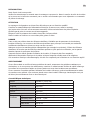
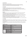
Technical data
Model PHÖNIX-L (1-030-315)
Cabin material Canadian red cedar
Length 1450 mm
Width(depth) 1020 mm
Height 2000 mm
Voltage 230volt 50Hz
Radiators Type Halogen radiators with red glass
Total output 2200W 9.6A
Back panel 300W x 4
Front panel 300W x 2
Calves 400W x 1

3/12
EN
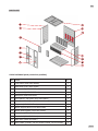
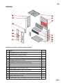
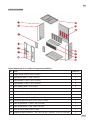
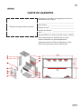
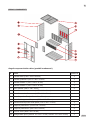
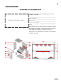
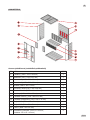
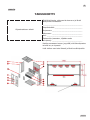
Cabin Individual parts (variations possible)
NO NAME Q’TY
1Floor panel (1450*l020*65mm) 1
2Back panel (1927*l392*43mm) 1
3Side panel 1 (1927*593*33mm) 1
4Side panel 2 (1927*593*33mm) 1
5 Side glass (1896*344*6mm) 2
6Front panel 1 with glass (1927*409*48mm) 1
7 Front panel 2 with glass (1927*409*48mm) 1
8 Toppanel (1450*l020*65mm) 1
9Bench support panel (1350*468*33mm) 1
10 Bench surface panel (1350*500*33mm) 1
11 Guardrail 1 (1350*650*54mm) 1
12 Guardrail 2 (260*650*54mm) 2
13 Glass door (1866*592*6mm) 1
14 Door handle (outside, 300*65*45mm & inside, 230*65*45mm) 2
PARTS LIST

4/12
EN
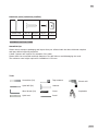
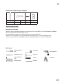
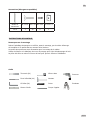
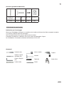
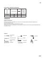
Hardware parts (variations possible)
Rubber rip Φ3*16 Φ4*45 Φ6*60 30*20*2
10m 1x 43x 2x 1x
Assemble tips
Please remove transport packaging and inspect that your infrared cabin has been delivered complete
and intact before beginning assemble.
A lea 2 persons are required for assemble of the cabin
Please check the countersink and hole diameter of the drill holes to avoid damaging the wood.
The minimum room height required for inallation is 2120 mm
Tools
ASSEMBLE INSTRUCTIONS
Pencil
Spirit level
Allen Wrench (kit)
Spiral drill (kit)
Screwdriver (kit)
Cutter
Hammer
Tape measure Electric drill
Stepladder

5/12
EN
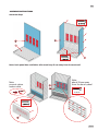
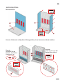
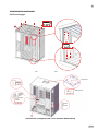
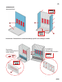
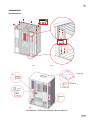
Assemble eps
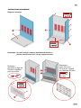
ASSEMBLE INSTRUCTIONS
Note: back panel has ventilation slits must keep 5 cm away from the next wall
8-Φ4*45
Note:
connect calves
heater cable
Note:
about 20mm away
from the bench panel

6/12
EN
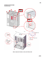
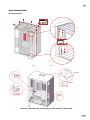
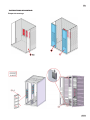
ASSEMBLE INSTRUCTIONS
Assemble eps
Mutteri

7/12
EN
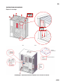
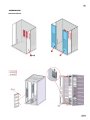
ASSEMBLE INSTRUCTIONS
Note: connect all cables on the roof of the cabin
8-Φ4*45
Assemble eps

8/12
EN
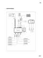
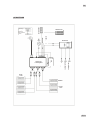
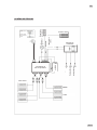
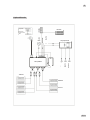
Plug ripe
CIRCUIT DIAGRAM
Antenna
Speaker
Speaker

9/12
EN
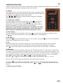
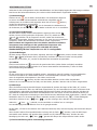
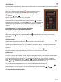
OPERATING INTRUCTIONS
Connect the power unit to wall outlet, the LED indicator will art to blink on the display. Now it is possible to
switch on the infrared heaters, the light and the music function.
1) Startup
Press to switch on the cabin and heaters art to work, the length of time
is automatically set to 99 minutes and the air temperature inside the cabin will
be displayed. Press again switch o the heaters.
Press
, or
separately to adju the power intensity of front/back/
calves heaters from 100%-0%.
2) Temperature settings
The upper display refers to the air temperature. Press , you can set the
desired temperature (35-60°C) using the / keys. When at this
temperature, the heaters will op working automatically; When it fall 4°C
below this temperature, the cabin will art up automatically.
Please note: The maximum air temperature reachable in the cabin
may be lower than the desired temperature. This is dependent on
the temperature outside the cabin. Default temperatur = 40°C.
3) Time settings
The lower display refers to the length of time. Press , you can set the desired time (5-90mins) using
the / keys. When countdown to “00”, the heaters will shut o automatically.
4) Sky light
Short press , you can set the desired colour (7 colors totally); Long press to go into an automatically
cycling mode, changing colour every 5 seconds.
5) Fan
The fan has three modes: automatic, manual, close. The automatic mode is present when the heaters
switch on. In automatic mode, the fan switches on when the set cabin air temperature is reached.
Press once for manual mode, the fan switches on. Press once more for close mode, it switches o.
6) MP3 player
In the condition of connecting electricity, long press „M“, the MP3-player power on, (if the player is inserted with
an USB-disc, it will acquiescently play USB le), otherwise, the MP3 player will turn on Bluetooth by default. Then
turn on the Bluetooth search function of mobile phone and search „FJF - BT“ Bluetooth device. The MP3 player can
play music after successfully connecting the phone (Note: each mobile phone ju can connect one MP3 player).
Press „ “ to pause playing. Press „ “ or „ “ to play the previous/next song.
Press the „ “ or „ “key to adju the volume plus or minus, the adjument range is 0 - 30 level.
Press the „M“ key, the MP3 player cycle Bluetooth- MP3 external input-FM function.
Long press „ “ in the FM ate, the MP3 player search and sace the channels automatically (channels from
87.5 MHz to 108.5 MHz). After the searching nish, press „ “ or „ “, the MP3 player broadca the ored
channels.
7) Remote control included

10/12
EN
SERVICE
Notes:
Use inructions
Drink plenty of liquids before and after use of the infrared cabin.
Dry yourself o completely.
The optimal cabin temperature for a pleasant session lies between 35 and 40°C.
After a heating period of an hour at the late, the cabin should be switched o and a heating brake of
at lea 30 minutes should be taken.
It is recommended to take a warm shower and relax after use.
Maintenance inructions
Clean the cabin with a damp cotton towel, dry with a clean dry towel.
Clean the glass with a window/glass cleaner and a soft cloth.
Do not pour water in the control panel or clean it with wet cloth. For cleaning purposes, use a cleaning cloth
that has been only slightly moiened with a mild soapy solvent (dish detergent).
Do not use chemical detergents to clean the cabin.
Please faen the screws of the bench once every three months, avoid the loose or drop o.

11/12
EN
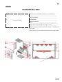
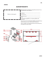
GUARANTEE CARD
SERVICE
Control unit label
Fill in this form and make a picture of it and Email to:
______________________________________________
Date of purchase: _______________________________
Serial Number: _________________________________
Reference number: ______________________________
Name: ________________________________________
Article state (unopened, just opened or used): ________
Please encircle on picture below which heater or which panel
has a fault.
Attach pictures of the problem and send them through email.

12/12
EN
sentiotec GmbH | Division of Harvia Group | Wartenburger Straße 31, A-4840 Vöcklabruck
T +43 (0) 7672/22 900-50| F -80 | [email protected] | www.sentiotec.com

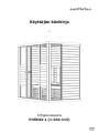
1/12
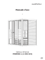
Benutzerhandbuch
DE
Infrarotkabine
PHÖNIX-L (1-030-315)
03/2021

2/12
DE
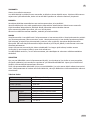
EINLEITUNG
Vielen Dank, dass Sie sich für unser Produkt entschieden haben.
Bitte lesen Sie dieses Handbuch vor der Montage sorgfältig durch und bewahren Sie es auf. Schreiben Sie sich
die Seriennummer der Kabine am Schaltkaen auf, da diese Nummer bei Reparaturen oder der Beellung
von Ersatzteilen erforderlich i.
ACHTUNG
Montage und Reparatur dürfen nur von einem qualizierten Elektriker durchgeführt werden!
Überprüfen Sie die Stromversorgungsleiung und ellen Sie vor der Montage sicher, dass die geerdete
Steckdose ordnungsgemäß angeschlossen i. Verwenden Sie ausschließlich Originalteile. Verwenden Sie
die Steckdose nicht zusammen mit anderen Geräten.
Schalten Sie die Leiungseinheit der Kabine aus, wenn sie nicht verwendet wird.
Stellen Sie die Kabine in einem Innenraum auf einer achen, ebenen und trockenen Fläche auf.
GEFAHR
Auf die Heizkörper darf kein Wasser gelangen. In der Infrarotkabine darf kein Duschkopf inalliert werden.
Bei Abdeckung der Heizelemente beeht Brandgefahr durch Überhitzung. Die Heizkörper dürfen keinesfalls
abgedeckt werden!
Halten Sie feuergefährliche oder leicht entammbare Materialien/Objekte (beispielsweise Handtücher) ets
von den Heizelementen fern. Die Heizelemente dürfen während und kurz nach der Benutzung nicht berührt
werden, da aufgrund heißer Teile Verbrennungsgefahr beeht.
Das Leuchtmittel wird während der Verwendung der Kabine heiß. Muss das Leuchtmittel ausgetauscht werden,
trennen Sie die Stromversorgung der Kabine und lassen Sie das Leuchtmittel vor dem Auswechseln abkühlen.
Wird der Elektroanschluss beschädigt, muss er entweder vom Hereller oder von einem lizenzierten Elektriker
ausgetauscht werden!
WARNUNG
Wenn Sie krank sind oder andere gesundheitliche Probleme haben, insbesondere Herzleiden oder
Kreislauförungen, oder Medikamente einnehmen, sollten Sie vor Nutzung der Infrarotkabine einen Arzt
befragen. Kinder und gebrechliche Personen dürfen sich niemals ohne Aufsicht in der Kabine benden.
Wenn Sie während der Nutzung der Infrarotkabine Unbehagen verspüren, verlassen Sie die Kabine sofort und
konsultieren Sie Ihren Arzt. Nach der Einnahme von Alkohol, arken Medikamenten oder Betäubungsmitteln
dürfen Sie auf keinen Fall die heiße Infrarotkabine betreten!
Technische Daten
Modell PHÖNIX-L (1-030-315)
Kabinenmaterial Kanadische rote Zeder
Länge 1450 mm
Breite (Tiefe) 1020 mm
Höhe 2000 mm
Spannung 230 Volt, 50 Hz
Heizele-
mente
Typ Halogen-Heizelemente mit rotem Glas
Gesamtleiung 2200W 9,6 A
Rückwand 300W x 4
Vorderwand 300W x 2
Waden 400W x 1

3/12
DE
Einzelteile der Kabine (Abweichungen möglich)
NR. NAME MENGE
1Bodenplatte (1450 x 1020 x 65 mm) 1
2Rückwand (1927 x 1392 x 43 mm) 1
3Seitenwand 1 (1927 x 593 x 33 mm) 1
4Seitenwand 2 (1927 x 593 x 33 mm) 1
5 Seitenglas (1896 x 344 x 6 mm) 2
6Vorderwand 1 mit Glas (1927 x 409 x 48 mm) 1
7 Vorderwand 2 mit Glas (1927 x 409 x 48 mm) 1
8 Deckenplatte (1450 x 1020 x 65 mm) 1
9Bankützplatte (1350 x 468 x 33 mm) 1
10 Bankoberächenplatte (1350 x 500 x 33 mm) 1
11 Schutzgitter 1 (1350 x 650 x 54 mm) 1
12 Schutzgitter 2 (260 x 650 x 54 mm) 2
13 Glaür (1866 x 592 x 6 mm) 1
14 Türgri (außen: 300 x 65 x 45 mm; innen: 230 x 65 x 45 mm) 2
TEILELISTE

4/12
DE
Zubehörteile (Abweichungen möglich)
Gummireifen Φ 3 x 16 Φ 4 x 45 Φ 6 x 60 30 x 20 x 2
10 m 1 Stk. 43 Stk. 2 Stk. 1 Stk.
Hinweise zur Montage
Entfernen Sie die Transportverpackung und prüfen Sie vor der Montage, ob die Infrarotkabine volländig
und in einwandfreiem Zuand geliefert wurde.
Für die Montage der Kabine sind mindeens zwei Personen erforderlich.
Überprüfen Sie die Senkung und den Durchmesser der Bohrlöcher, um eine Beschädigung des
Holzes zu vermeiden. Für die Inallation i eine Minderaumhöhe von 2120 mm erforderlich.
Werkzeuge
MONTAGEANLEITUNG
Bleiift
Wasserwaage
Inbus-Schlüssel
(Kit)
Spiralbohrer (Kit)
Schraubendreher
(Kit)
Cutter
Hammer
Bandmaß Bohrmaschine
Stehleiter

5/12
DE
Montageschritte
MONTAGEANLEITUNG
Hinweis: Rückwand verfügt über Lüftungsschlitze; 5 cm Abstand zur Wand einhalten
8-Φ4*45
Hinweis:
Schließen Sie das
Kabel für das Waden-
Heizelement an.
Hinweis:
etwa 20 mm von der
Bankplatte entfernt

6/12
DE
MONTAGEANLEITUNG
Montageschritte

7/12
DE
Hinweis: Schließen Sie alle Kabel auf dem Dach der Kabine an
MONTAGEANLEITUNG
Gri
Glaür
Gri
Gummi
reifen
Netzteil
Steuerung
8-Φ4*45
Montageschritte

8/12
DE
Waden
Vorder-
seite
Rück-
seite
Steuerung
Leiungeil
SCHALTPLAN
Bedienteil
Antenne
Lautsprecher
Farbleuchte
Lüfter
Temperaturfühler
(Dach)
Lautsprecher
Netz-
teil
Leiung
Nennrom
Sicherheitsufe
Modell
Spannung
Steckerleie
La pagina si sta caricando...
La pagina si sta caricando...
La pagina si sta caricando...
La pagina si sta caricando...
La pagina si sta caricando...
La pagina si sta caricando...
La pagina si sta caricando...
La pagina si sta caricando...
La pagina si sta caricando...
La pagina si sta caricando...
La pagina si sta caricando...
La pagina si sta caricando...
La pagina si sta caricando...
La pagina si sta caricando...
La pagina si sta caricando...
La pagina si sta caricando...
La pagina si sta caricando...
La pagina si sta caricando...
La pagina si sta caricando...
La pagina si sta caricando...
La pagina si sta caricando...
La pagina si sta caricando...
La pagina si sta caricando...
La pagina si sta caricando...
La pagina si sta caricando...
La pagina si sta caricando...
La pagina si sta caricando...
La pagina si sta caricando...
La pagina si sta caricando...
La pagina si sta caricando...
La pagina si sta caricando...
La pagina si sta caricando...
La pagina si sta caricando...
La pagina si sta caricando...
La pagina si sta caricando...
La pagina si sta caricando...
La pagina si sta caricando...
La pagina si sta caricando...
La pagina si sta caricando...
La pagina si sta caricando...
-
 1
1
-
 2
2
-
 3
3
-
 4
4
-
 5
5
-
 6
6
-
 7
7
-
 8
8
-
 9
9
-
 10
10
-
 11
11
-
 12
12
-
 13
13
-
 14
14
-
 15
15
-
 16
16
-
 17
17
-
 18
18
-
 19
19
-
 20
20
-
 21
21
-
 22
22
-
 23
23
-
 24
24
-
 25
25
-
 26
26
-
 27
27
-
 28
28
-
 29
29
-
 30
30
-
 31
31
-
 32
32
-
 33
33
-
 34
34
-
 35
35
-
 36
36
-
 37
37
-
 38
38
-
 39
39
-
 40
40
-
 41
41
-
 42
42
-
 43
43
-
 44
44
-
 45
45
-
 46
46
-
 47
47
-
 48
48
-
 49
49
-
 50
50
-
 51
51
-
 52
52
-
 53
53
-
 54
54
-
 55
55
-
 56
56
-
 57
57
-
 58
58
-
 59
59
-
 60
60


in altre lingue
- English: Sentiotec Phönix Large User manual
- français: Sentiotec Phönix Large Manuel utilisateur
- eesti: Sentiotec Phönix Large Kasutusjuhend
Documenti correlati
-
Sentiotec Phönix Medium Manuale utente
-
-
-
-
-
-
-
-
-
