ROBLIN ALTIMA Manuale del proprietario
- Categoria
- Cappe da cucina
- Tipo
- Manuale del proprietario

Notice
ALTIMA
GROUPE ASPIRANT
CONCEPTION
FABRICATION
FRANÇAISE

F SOMMAIRE
RACCORDEMENT ÉLECTRIQUE
CONSEILS D’INSTALLATIONS
POSE DE L’APPAREIL
FONCTIONNEMENT
CONSEILS D’UTILISATIONS
ENTRETIEN
GARANTIE ET SERVICE APRÈS-VENTE
REMARQUES
D INHALT
NETZANSCHLUSS
MONTAGEHILFEN
MONTAGE DES GERÄTES
BETRIEB DES GERÄTES
NUTZUNG
WARTUNG UND REINIGUNG
GARANTIE UND KUNDENDIENST
WICHTIGE HINVEISE
E SUMARIO
CONEXION ELECTRICA
CONSEJOS DE INSTALACION
INSTALACION DEL APARATO
FUNCIONAMIENTO
CONSEJOS DE UTILIZACION
MANTENIMIENTO
GARANTIA Y ASSISTENCIA TECNICA
NOTA
GB CONTENTS
ELECTRICAL WIRING
INSTALLATION ADVICE
FITTING THE APPLIANCE
OPERATION
USEFUL HINTS
MAINTENANCE
GUARANTEE AND AFTER-SALES-SERVICES
REMARKS
I CONTENUTI
COLLEGAMENTO ELETTRICO
CONSIGLI DI INSTALLAZIONE
POSA DELL’ APPARECCHIO
FUNZIONAMENTO
CONSICLI DI UTILIZZO
MANUTENZIONE
GARANZIA ED ASSISTENZA TECNICA
NOTE
NL INHOUD
ELECTRISCHE BEDRADING
MONTAGE AANWIJZING
AANSLUITEN VAN HET APPARAAT
FUNKTIONEREN
GEBRUIKSADVIES
ONDERHOUD
AFTER SALES SERVICE
OPMERKINGEN

1
F
Nous vous remercions de la conance que vous nous avez accordée en choisissant un appareil de la
gamme ROBLIN.
Celui-ci a fait l’objet de toute notre attention dans sa conception et sa réalisation.
An qu’il vous donne entière satisfaction, nous vous recommandons de lire avec attention cette notice qui
vous expliquera comment l’installer, l’utiliser et l’entretenir dans les meilleures conditions.
La présente notice d’emploi vaut pour plusieurs versions de l’appareil. Elle peut contenir des descriptions
d’accessoires ne gurant pas dans votre appareil.
1 RACCORDEMENT ÉLECTRIQUE.
• La hotte est équipée d’un cordon d’alimentation de type HO5VVF 3 x 0,75 mm² comportant une
che normalisée 10/16 A avec système de mise à la terre.
Mode de protection : classe I. Tension d’alimentation : 220-240 V mono - 50Hz / 220 V - 60Hz.
Vérier que la tension du secteur est identique aux valeurs indiquées sur la plaque signalétique à
l’intérieur de la hotte
• Si la hotte est raccordée directement sur le réseau sans sa che, un interrupteur omnipolaire avec
une ouverture de contact de 3 mm doit être installé avant la hotte. Le l de terre (Jaune / vert) ne doit
pas être interrompu par cet interrupteur.
2 CONSEILS D’INSTALLATION.
• Respecter le diamètre de sortie de l’appareil : la hotte ne doit en aucun cas être raccordée à un
conduit de ventilation mécanique contrôlée (V.M.C.).
• Lorsqu’on évacue l’air vicié
dans un conduit d’évacuation, veiller à ce que celui-ci ne soit pas déjà
exploité à véhiculer des gaz ou fumées provenant d’appareils alimentés par une énergie autre qu’élec-
trique.
• Positionner le plan de cuisson au plus près de l’évacuation et éviter la formation de coudes sur la
gaine, an de réduire au maximum les pertes de charges.
• Dans tous les cas d’installation, veiller au bon renouvellement d’air de la cuisine. Penser à ef-
fectuer une ou des entrées d’air par une grille de section égale ou supérieure au diamètre du tuyau
d’évacuation, an de ne pas mettre la cuisine en dépression.
• Prévoir une aération sufsante lorsqu’un appareil de cuisson ou autre utilise simultanément l’air
ambiant de la pièce où est installée la hotte.
• La dépression maximum crée dans la pièce doit être inférieur à 0.04 mbar, ce qui évite un retour de
gaz de combustion.
• L’appareil doit être positionné de telle façon que la che d’alimentation soit accessible.
• Cet appareil ne doit pas être utilisé par des personnes (y compris les enfants) ayant des capacités
psychiques, sensorielles ou mentales réduites, ni par des personnes n’ayant pas l’expérience et la
connaissance de ce type d’appareils, à moins d’être sous le contrôle et la formation de personnes res-
ponsables de leur sécurité.
• Les enfants doivent être surveillés pour s’assurer qu’ils ne jouent pas avec l’appareil.

2
F
3 POSE DE L’APPAREIL.
Montage et raccordement doivent être réalisés par un installateur* qualié.
(*) Le non-respect de cette condition entraîne la suppression de la garantie du constructeur et
tout recours en cas d’accident.
Attention: prendre bien soin d’employer les chevilles adaptées au support, se renseigner au près
des fabricants, effectuer un scellement si nécessaire. La société décline toute responsabilité en
cas d’accrochage défectueux dû au perçage et chevillage.
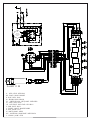
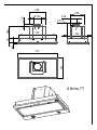
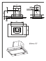
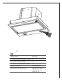
Le groupe d’aspiration s’encastre dans le plancher de la hotte (épaisseur: 12 à 22 mm). (Fig 1)
Raccorder la che électrique, mettre en place la tuyauterie d’évacuation.Engager l’appareil dans la
découpe et xer le avec les 4 vis fournis.
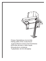
•Recyclage:
L’air ltré est evacué dans la pièce à travers une ouverture placée sur la partie supérieure du meuble
ou de la hotte (Fig. 2). Ajoutez le ltre à charbon actif à l ’intérieur du corps du groupe (Fig 3).
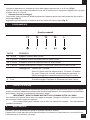
4 FONCTIONNEMENT
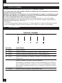
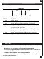
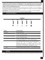
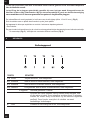
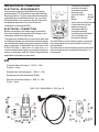
Tableau des commandes
T1 T2 T3 T4 L
TOUCHE FONCTIONS
T1 Moteur Coupe le moteur.
T2 Vitesse Démarre le moteur à la première vitesse. Touche allumée fixe.
T3 Vitesse Démarre le moteur à la deuxième vitesse. Touche allumée fixe.
T4 Vitesse Appuyée brièvement, elle démarre le moteur à la troisième vitesse. Touche
allumée fixe.
Appuyée pendant 2 secondes. Touche clignotante.
Elle démarre la quatrième vitesse avec une temporisation de 10 minutes,
après lesquelles le moteur retourne à la vitesse précédemment program-
mée. Fonction indiquée pour faire face aux pointes d’émission de fumées
de cuisson
L Lumière Allume et éteint l’éclairage. Touche allumée fixe.

3
F
5 CONSEILS D’UTILISATION.
• Pour obtenir une efcacité maximum d’absorption des fumées ou des vapeurs, faire fonctionner
l’appareil 5 minutes environ avant et après la cuisson des aliments; La première vitesse est conseillée
pour les cuissons à feu doux et pour les sauces. La deuxième pour les cuissons soutenues, grillades et
friteuses. La troisième est indiquée pour les cuissons à forte émanation de graisses et vapeur.
• IMPORTANT . NE JAMAIS FLAMBER DE METS AU DESSOUS DE L’APPAREIL
Ne laissez jamais de ammes libres sous la hotte en fonctionnement.
• Les fritures nécessitent une surveillance permanente, l’huile surchauffée pouvant s’enammer.
6 ENTRETIEN.
Déconnecter le câble d’alimentation pour toute intervention électrique.
L’appareil a été conçu pour faciliter au maximum les opérations d’entretien, synonyme de bon fonction-
nement et rendement de l’appareil dans le temps.
• Nettoyage des ltres métalliques.
Il est indispensable de procéder à un NETTOYAGE PÉRIODIQUE de ces ltres à la main (avec un déter-
gent liquide à l’eau tiède et rinçage) ou au lave- vaisselle (tous les deux mois environ pour une utilisation
normale).
• Carrosserie.
Nettoyer régulièrement celle-ci en utilisant des produits détergents, non abrasifs et une éponge légèrement
humide. N’utilisez jamais d’éponges ou de chiffons trempés
N’introduisez aucun objet, ni les mains dans l’ouverture servant à l’évacuation de l’air
• Conduit d’évacuation.
Vérier tous les 6 mois le bon écoulement de l’air vicié.
Observer les prescriptions réglementaires locales concernant l’évacuation de l’air vicié.
• Éclairage.
Avant toute intervention sur l’appareil, mettre l’interrupteur d’allumage des lampes en position éteinte.
Ne pas dépasser la puissance prescrite et ne pas changer de type de lampe.
7 GARANTIE ET SERVICE APRÈS-VENTE.
• En cas d’anomalie de fonctionnement, prévenez votre installateur qui devra vérier l’appareil et son
raccordement.
• Dans le cas où un composant électrique viendrait à être endommagé, celui-ci ne peut être remplacé
que par un atelier de réparation reconnu par le fabricant, car des outils spéciaux sont nécessaires.
• Débrancher complètement l’appareil.
• Exigez toujours l’utilisation de pièces de rechange d’origine. La non observation de cette prescription
peut compromettre la sécurité de l’appareil.
• Lors de la commande de pièces détachées, rappeler le numéro de l’appareil inscrit sur la plaque
signalétique située à l’intérieur de la hotte.
• Seule la facture d’achat de l’appareil fera foi pour l’application de la garantie contractuelle.
Cette garantie ne couvre pas les consommables comme :
- L’éclairage : lampes incandescentes, halogènes ...
- Les ltres.

4
sécurité électrique et aux normes européennes: 2004/108/CE relative à la compatibilité électromagnétique
et 93/68 relative au marquage CE.
Lorsque ce symbole d’une poubelle à roue barrée est attaché à un produit, cela signie que le
produit est couvert par la Directive Européenne 2002/96/EC. Votre produit est conçu et fabriqué avec
des matériaux et des composants de haute qualité, qui peuvent être recyclés et utilisés de nouveau.
Veuillez vous informer du système local de séparation des déchets électriques et électroniques. Veuillez
agir selon les règles locales et ne pas jeter vos produits usagés avec les déchets domestiques usuels.
Jeter correctement votre produit usagé aidera à prévenir les conséquences négatives potentielles contre
l’environnement et la santé humaine.
F
9 CONSEILS POUR L’ECONOMIE D’ENERGIE.
Lorsque vous commencez à cuisiner, activer la hotte à la vitesse minimum pour contrôler l’humidité et
éliminer les odeurs de cuisine.
Utilisez la vitesse intensive lorsque cela est strictement nécessaire.
Augmentez la vitesse de la hotte seulement lorsque la quantité de vapeur le requiert.
Veillez à ce que le ou les filtres de la hotte soient toujours propres, afin d’optimiser l’éfficacité
anti-graisse et anti-odeurs.
8 REMARQUES.
Cet équipement est conforme à la norme européenne sur la basse tension 2006/95/CE relative à la

5
GB
Thank you for buying a ROBLIN product which has been manufactured to the highest quality standards
to meet your requirements.
We recommend you carefully read this booklet in which you will nd instructions for installation, hints for
use and maintenance.
The Instructions for Use apply to several versions of this appliance. Accordingly, you may nd descrip-
tions of individual features that do not apply to your specic appliance.
1 ELECTRICAL
• This cooker hood is tted with a 3-core mains cable with a standard 10/16A earthed plug.
• Alternatively the hood can be connected to the mains supply via a double-pole switch having 3mm
minimum contact gap on each pole.
• Before connecting to the mains supply ensure that the mains voltage corresponds to the voltage on
the rating plate inside the cooker hood.
• Technical Specication: Voltage 220-240 V, single phase ~ 50 Hz / 220 V - 60Hz.
2 INSTALLATION ADVICE
• Ensure the cooker hood is tted in compliance with the recommended xing heights
• It is a possible re risk if the hood is not sited as recommended.
• To ensure the best results, the cooking fumes should be able to rise naturally towards the inlet grilles
on the underside of the cooker hood and the cooker hood should be positioned away from doors and
windows, which will create turbulence.
• Ducting
• If the room where the hood is to be used contains a fuel-burning appliance such as a central heating
boiler then its ue must be of the room sealed or balanced ue type.
• If other types of ue or appliances are tted ensure that there is an adequate supply of fresh air to
the room. Ensure the kitchen is tted with an airbrick, which should have a cross-sectional measurement
equivalent to the diameter of the ducting being tted, if not larger.
• The ducting system for this cooker hood must not be connected to any existing ventilation system,
which is being used for any other purposes or to a mechanically controlled ventilation ducting.
• The ducting used must be made from re retardant materials and the correct diameter must be
used, as incorrect sized ducting will affect the performance of this cooker hood.
• When the cooker hood is used in conjunction with other appliances supplied with energy other than
electricity, the negative pressure in the room must not exceed 0.04 mbar to prevent the fumes from
combustion being drawn back into the room.
•
The appliance is for domestic use only and should not be operated by children or people who are
inrm without supervision.
•
This appliance must be positioned so that the wall socket is accessible.
•
This appliance is
not intended for
use by persons (including children) with reduced physical, sensory
or mental capabilities, or lack of experience and knowledge, unless they have been given supervision or
instruction concerning use of the appliance by a person responsible for their safety.
Children should be supervised to ensure that they do not play with the appliance.
•
• 3 FITTING
Any permanent electrical installation must comply with the latest regulations concerning this type of instal-
lation and a qualied electrician must carry out the work. Non-compliance could cause serious accidents
or injury and would deem the manufacturers guarantee null and void.
IMPORTANT - The wires in this mains lead are coloured in accordance with the following code :
green / yellow : earth blue : neutral brown : live
As the colours of the wires in the mains lead of this appliance may not correspond with the coloured
markings identifying the terminals in your plug, proceed as follows.

6
GB
- The wire which is coloured green and yellow must be connected to the terminal in the plug which is
marked with the letter E or by the earth symbol or coloured green or green and yellow.
- The wire which is coloured blue must be connected to the terminal which is marked with the letter N
or coloured black.
- The wire which is coloured brown must be connected to the terminal which is marked with the letter
L or coloured red.
ATTENTION: Do not forget to use adequate plugs to the support brackets. Enquire after the manu-
facturers. Do an embedding if necessary. The manufacturer accepts no responsibility in case of a
faulty hanging due to the drilling and the setting up of plugs.
The extractor unit is tted into the base board of the cooker hood (thickness: 12 to 22 mm). (Fig 1)
Connect the electrical plug and set the extractor tube in place. Fit the appliance into the cutout
and x it with the 4 screws supplied.
The hood is more effective when used in the extraction mode (ducted to the outside). When the cooker
hood is ducted to the outside, charcoal lters are not required.The ducting used must be 150 mm (6 INS),
rigid circular pipe and must be manufactured from re retardant material, produced to BS.476 or DIN
4102-B1. Wherever possible use rigid circular pipe which has a smooth interior, rather than the expanding
concertina type ducting.
Maximum length of ducting run:
- 4 metres with 1 x 90° bend.
- 3 metres with 2 x 90° bends.
- 2 metres with 3 x 90° bends.
The above assumes our 150 mm (6 INS) ducting is being installed. Please note ducting components
and ducting kits are optional accessories and have to be ordered, they are not automatically supplied with
the chimney hood.
•RECYCLING : The air is recirculated into the kitchen through the opening located on the upper side of
the cabinet or of the hood (Fig. 2). Install the charcoal lters inside the canopy (Fig 3).

7
GB
4 OPERATION
5 USEFUL HINTS
• To obtain the best performance we recommend you to switch ‘ON’ the cooker hood a few minutes (in
the boost setting) before you start cooking and you should leave it running for approximately 15 minutes
after nishing.
• IMPORTANT: NEVER DO FLAMBÉ COOKING UNDER THIS COOKER HOOD
• Do not leave frying pans unattended during use as over-heated fat and oil might catch re.
• Do not leave naked ames under this cooker hood.
• Switch ‘OFF’ the electric and gas before removing pots and pans.
• Ensure heating areas on your hotplate are covered with pots and pans when using the hotplate
and cooker hood simultaneously.
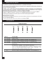
Control panel
T1 T2 T3 T4 L
BUTTON FUNCTIONS
T1 Motor Turns the Motor off.
T2 Speed Turns the Motor on at Speed one. Button lights up continuously.
T3 Speed Turns the Motor on at Speed two. Button lights up continuously.
T4 Speed When pressed briefly, turns the Motor on at Speed three. Button lights up
continuously.
Pressed for 2 Seconds. Button flashes.
Activates Speed four with a timer set to 10 minutes, after which it returns
to the speed that was set previously. Suitable to deal with maximum levels
of cooking fumes.
L Light Turns the Lighting System on and off. Button lights up continuously.

8
6 MAINTENANCE
Before carrying out any maintenance or cleaning isolate the cooker hood from the mains supply.
The cooker hood must be kept clean; a build up of fat or grease may cause a re hazard.
Casing
• Wipe the cooker hood frequently with a clean cloth, which has been immersed in warm water contain-
ing a mild detergent and wrung out.
• Never use excessive amounts of water when cleaning particularly around the control panel.
• Never use scouring pads or abrasive cleaners.
• Always wear protective gloves when cleaning the cooker hood.
Metal Grease Filters : The metal grease lters absorb grease and dust during cooking in order to keep
clean the cooker hood inside. The grease lters should be cleaned once a month or more frequently if
the hood is used for more than 3 hours per day.
To remove and replace the metal grease lters
• Remove the metal grease lters one at a time by releasing the catches on the lters; the lters can
now be removed.
• The metal grease lters should be washed, by hand, in mild soapy water or in a dishwasher.
• Allow to dry before replacing.
Active Charcoal Filter : The charcoal lter cannot be cleaned. The lter should be replaced at least
every three months or more frequently if the hood is used for more than three hours per day.
To remove and replace the lter
• Remove the metal grease lters.
• Press against the two retaining clips, which hold the charcoal lter in place and this will allow the lter
to drop down and be removed.
• Clean the surrounding area and metal grease lters as directed above.
• Insert the replacement lter and ensure the two retaining clips are correctly located.
• Replace the metal grease lters.
Extraction tube : Check every 6 months that the dirty air is being extracted correctly. Comply with local
rules and regulations with regard to the extraction of ventilated air.
Lighting : If the lamp fails to function check to ensure it is tted correctly into the holder. If lamp failure
has occurred then it should be replaced with identical replacement.
Do not replace with any other type of lamp and do not t a lamp with a higher rating.
7 GUARANTEE AND AFTER SALES SERVICE
• In the event of any malfunction or anomaly, notify your tter who will have to check the ap-
pliance and its connection.
• In the event of damage to the mains supply cable, this can only be replaced by at approved repair
centre appointed by the manufacturer who will have the required tools and equipment to carry out any
repairs properly. Repairs carried out by other persons will invalidate the guarantee.
• Use only genuine spare parts. Should these warnings fail to be observed it could affect the safety of
your cooker hood.
• When ordering spare parts quote the model number and serial number written on the rating plate,
which is found on the casing behind the grease lters inside the hood.
• Proof of purchase will be required when requesting service. Therefore, please have your receipt
available when requesting service as this constitutes the date from which your guarantee commenced.
This Guarantee does not cover :
- Damage or calls resulting from transportation, improper use or neglect, the replacement of any light
bulbs or lters or removable parts of glass or plastic.
These items are considered to be consumable under the terms of this guarantee.
GB

9
8 REMARKS
This appliance complies with European regulations on low voltages Directive 2006/95/CE on electrical
safety, and with the following European regulations: Directive 2004/108/CE on electromagnetic compat-
ibility and Directive 93/68 on EC marking.
When this crossed-out wheeled bin symbol
is attached to a product it means the product is cov-
ered by the European directive 2002/96/EC.Your product is designed and manufactured with high quality
materials and components, which can be recycled and reused.Please inform yourself about the local
separate collection system for electrical and electronic product. Please act according to your local rules
and do not dispose of your old products with your normal household waste. The correct disposal of your
old product will help prevent potential negative consequences for the environment and human health.
GB
9 ENERGY SAVING TIPS.
When you start cooking, switch on the range hood at minimum speed, to control moisture and remove
cooking odor.
Use boost speed only when is strictly necessary.
Increase the range speed only when the amount of vapor makes it necessary.
Keep range hood filter(s) clean to optimize grease and odor efficiency.

10
D
Wir danken Ihnen für Ihre Kaufentscheidung und das Vertrauen, welches Sie mit dem Kauf dieses
ROBLIN-Produktes bewiesen haben.
Di e s es Gerät wurd e mit einem hohe n Maß an Kr ea t i vi t ä t entwic k e lt und mit
größter Sorgfalt gefertigt.
Um volle Zufriedenheit mit Leistung und Funktion dieser Dunstesse zu erlangen und zu erhalten, emp-
fehlen wir dringend, sowohl die Montage-anweisung sorgfältig zu beachten und danach zu arbeiten als
auch die “ Gebrauchs- und Wartungshinweise ” aufmerksam zu lesen und anzuwenden.
Diese Gebrauchsanleitung gilt für mehrere Geräte-Ausführungen. Es ist möglich,
dass einzelne Ausstattungsmerkmale beschrieben sind, die nicht auf Ihr Gerät zutreffen.
1 NETZANCHLUSS
• Die Dunstabzugshaube ist mit einer Anschlußleitung der Art HO5VVF 3 x 0,75 mm
2
, die einen
Schutzstecker 10 / 16 A enthält, ausgestattet. Das entspricht Schutzklasse 1.
Nennspannung : 220 - 240 V - Wechselstrom : 50 Hz / 220 V - 60 Hz.
• Es ist sicherzustellen, daß die Netzspannung den Anschlußwerten auf dem Typenschild im Inneren
der Dunstesse entspricht.
• Beim Anschluß der Dunstesse an das Wechselstromnetz ist ein zweipoliger Schalter mit einem
Öffnungsweg von wenigstens 3 mm für jeden Pol zwischenzuschalten.
2 MONTAGEHILFEN
• Der Außendurchmesser am Gebläseabgang des Gerätes ist für die Wahl des Abluft-Rohrsystems zu
berücksichtigen : Die Dunstesse darf keinesfalls an eine Entlüftungsleitung mit Unterdruck angeschlossen
werden. Die Abluft darf nicht in einen Schornstein geleitet werden, der für die Abgase von Koch- oder
Heiz-Geräten, (Kohle-, Öl-, oder Gas-Öfen oder -Herde) benutzt wird.
• Die Kochstelle (und damit auch die Dunstesse) so planen und installieren, daß möglichst kurze
Wege für eventuelle Abluft-Rohrleitungen erreicht werden. (so wenige Umlenkungen [90°-Bögen] wie
möglich! Keine Querschnittsverengungen!
• Die gute Erneuerung der Luft in der Küche ist zu beachten. Denken Sie daran, einen oder mehrere
Lufteintritte durch eine Öffnung, die den gleichen Durchmesser hat wie die Abluftleitung, vorzusehen.
• Sorgen Sie für eine ausreichende Zuluft, wenn ein Koch- oder anderes Gerät die Luft des Raumes,
in dem die Dunstesse eingebaut ist, gleichzeitig verwendet. Ein gefahrloser Betrieb ist möglich, wenn
bei gleichzeitigem Betrieb von Dunstesse und Feuerstätte im Raum ein Unterdruck von höchstens 0.04
mbar erreicht wird und ein Rücksaugen der Feuerstättenabgase vermieden wird.
Das Gerät muß so installiert werden, daß der Geräte-Stecker leicht erreichbar ist.
• Dieses Gerät darf nicht von Personen, auch Kindern, mit verminderte
n psychischen, senso-
rischen und geistigern Fähigkeiten, oder von Personen ohne Erfahrung und Kenntnisse benutzt werden,
sofern sie nicht von für ihre Sicherheit verantwortlichen Personen beaufsichtigt und beim Gebrauch des
Geräts angeleitet werden.
Kinder dürfen sich nicht unbeaufsichtigt in der Nähe des Geräts aufhalten und auf keinen Fall mit dem
Gerät spielen.
3 MONTAGE DES GERÄTES
Montage und Anschluß müssen von einem qualizierten Installateur* durchgeführt werden.
(*) Wenn diese Bedingung nicht eingehalten wird, wird die Garantie des Herstellers, sowie jeder
Anspruch im Falle eines Unfalles aufgehoben.

11
D
Achtung ! Bitte beachten Sie bei der Montage das Gewicht der kompletten Dunstesse. Die Tragfä-
higkeit der Decke oder alternativ der Trägerplatte für diese Zugbelastung muss vor der Montage
geprüft und gegebenenfalls durch die Anbringung von geeigneten Befestigungs-oder Stabilisie-
rungselementen hergestellt werden. Kann eine hinreichende Tragfähigkeit nicht sichergestellt
werden, ist von einer Montage abzusehen.
Das Einbaugerät fügt sich in den Ausschnitt der Dunstabzugshaube ein (Stärke: 12 bis 22 mm).(Fig 1)
Den elektrischen Stecker anschlieBen, die Abluftrohre aufstellen. Das Gerät im Zerschneiden verpichten
und mit den 4 Schrauben befestigen geliefert.
•Umluftbetrieb: Die gelterte Luft wird durch die obere Öffnung in den Raum zurückgeleitet (Fig 2).
Abschließend werden die Aktivkohle-Filter in das Lüfterteil eingesetzt (Fig 3)
4 BETRIEB DES GERATES
Schalttafel
T1 T2 T3 T4 L
TASTE FUNKTIONEN
T1 Motor Stellt den Motor ab.
T2 Betriebsgeschwindigkeit Schaltet den Motor bei der ersten Betriebsgeschwindigkeit
ein. Taste leuchtet bleibend.
T3 Betriebsgeschwindigkeit Schaltet den Motor bei der zweiten Betriebsgeschwindigkeit
ein. Taste leuchtet bleibend.
T4 Betriebsgeschwindigkeit Schaltet den Motor durch kurzes Drücken bei der dritten
Betriebsgeschwindigkeit ein. Taste leuchtet bleibend.
Bei 2 Sekunden langem Drücken: Taste leuchtet blinkend.
Aktiviert die auf 10 Minuten geregelte vierte
Betriebsgeschwindigkeit, nach deren Ablauf zu der zuvor
eingestellten Geschwindigkeit zurückgekehrt wird. Für die
Beseitigung von sehr intensiven Kochdünsten geeignet.
L Licht Schaltet die Beleuchtung ein und aus. Taste leuchtet bleibend.
5 NUTZUNG
• Um ein optimales Absaugen der Kochschwaden zu erzielen, wird empfohlen, das Gerät vor dem

12
D
Kochen einzuschalten und nach dem Kochen noch einige Zeit nachlaufen zu lassen. Für die Speisen,
die wenig Dampf entwickeln, verwenden Sie vorzugsweise die kleine Geschwindigkeit.
• WICHTIG : NIEMALS UNTER DEM GERÄT FLAMBIEREN.
Niemals eine große Flamme bei eingeschalteter Dunstesse unbedeckt lassen.
Wenn der Topf weggenommen wird, ist die Flamme abzuschalten oder für einen kurzen Zeitraum auf
kleinste Stellung zu drehen, trotzdem aber unbedingt im Auge zu behalten.
Frittiergeräte, die unter der Dunstesse betrieben werden, sind während der gesamtem Betriebsdauer zu
beaufsichtigen: überhitztes Öl kann sich entzünden und die Haube in Brand setzen.
6 WARTUNG UND REINIGUNG
Vor jedem Eingriff im Gerät immer den Netzstecker ziehen, oder die Sicherung herausdrehen bzw. die
Stromzufuhr unterbrechen. Bei dem Einbau des Gerätes wurde besonders die Wartungs-Freundlichkeit
berücksichtigt.
• Herausnehmen des Metalllters : Es ist unerläßlich, diese Filter REGELMÄßIG falls notwendig
auch in kurzen Intervallen, mit der Hand (lauwarmes Wasser mit Waschmittel und Spülen) oder in der
Geschirrspülmaschine zu REINIGEN. Diese Maßnahmen vermindern die Brandgefahr (starke Fettrück-
stände sind leicht brennbar).
• Gehäuse. Keine nassen Tücher für die Reinigung der Oberächen der Dunstesse verwenden. Es
sollen nur milde Reinigungsmittel und leicht feuchte Tücher verwendet werden. Keine Gegenstände in
die Luftaustrittsöffnung stecken. Nicht in die Luftaustrittsöffnung greifen.
• Abluftleitung: Kontrollieren Sie von Zeit zu Zeit, daß der Luftkanal nicht verstopft ist. Diese Prüfung
muß halbjährlich durchgeführt werden. Die behördlichen Anforderungen, für die Ableitung der Abluft,
sind zu berücksichtigen.
• Beleuchtung: Bei Leuchtmittel-Wechsel in jedem Fall den Schalter der Beleuchtung ausschalten.
Die Art des Leuchtmittels nicht wechseln. Leistung nicht überschreiten.
7 GARANTIE UND KUNDENDIEST
• Bei Versagen des Gerätes benachrichtigen Sie Ihren Installateur, der das Gerät und seine Instal-
lation überprüfen wird.
• Wenn die Geräte-Zuleitung beschädigt wurde, darf diese nur von einer Reparaturwerkstatt ersetzt
werden, die vom Hersteller anerkannt ist, weil Sonderwerkzeuge nötig sind. Haube komplett abschal-
ten.
• Stets nur Original-Ersatzteile verwenden.
• Sollte diese Vorschrift nicht eingehalten werden, könnte die Sicherheit des Gerätes beeinträchtigt
werden. Außerdem erlischt die Garantie.
• Bei der Bestellung von Ersatzteilen geben Sie bitte die Nummer des Gerätes, die sich auf dem
Typenschild hinter dem Gehäuse bendet, an.
• Für die Anwendung der vertraglicher Garantie wird nur die Einkaufsrechnung des Gerätes ver-
bindlich anerkannt. Von der Garantieleistung ausgenommen sind:
- Die Beleuchtung : Klassik - und Halogenbeleuchtung
- Die Filter (Die Filter sind als Verbrauchsgüter anzusehen).
8 WICHTIGE HINWEISE
Dieses Gerät entspricht den europäischen Niederspannungsrichtlinien 2006/95/EWG zur elektrischen
Sicherheit, den europäischen Richtlinien 2004108/EWG zur elektromagnetischen Verträglichkeit und den

13
Richtlinien 93/68/EWG zur CE Kennzeichnung.
Das Symbol auf dem Produkt oder seiner Verpackung weist darauf hin, dass dieses Produkt nicht
als normaler Haushaltsabfall zu behandeln ist, sondern an einem Sammelpunkt für das Recycling von
elektrischen oder elektronischen Geräten abgegeben werden muss. Durch Ihren Beitrag zum korrekten
Entsorgen dieses Produktes schützen Sie die Umwelt und die Gesundheit Ihrer Mitmenschen. Umwelt
und Gesundheit werden durch falsches Entsorgen gefährdet. Weitere Informationen über das Recycling
dieses Produktes erhalten Sie von Ihrer kommunalen Behörde, den örtlichen Müllentsorgungsunterneh-
men oder von Ihrem Fachhändler.
D
9 TIPS VOOR ENERGIEBESPARING.
Schakel de afzuigkapop de laagste snelheid in wanner u met koken begint om de vochtigheidsgraad
te regelen en kookluchtjes te verwijderen.
Gebruik de hoogste snelheid alleen wanner dit bestist noodzakelijk is.
Verhoog de snelheid van de afzuigkap alleen wanner de hoeveelheid damp dit vereist.
Houd het filter/de filters van de afzuigkap schoon om de vetfilterings-en geurfilteringefficiëntie te
optimaliseren.

14
I
La ringraziamo per la ducia accordataci nell’aver scelto un prodotto della gamma ROBLIN.
Questo apparecchio è stato studiato e realizzato con la massima cura, secondo i più alti criteri di
qualità.
Le raccomandiamo di leggere attentamente questo opuscolo, nel quale troverà le istruzioni per
installare, utilizzare e conservare al meglio il suo apparecchio ed ottenere dal suo acquisto il massimo
dei beneci.
Questo libretto di istruzioni per l’uso è previsto per più versioni dell’ apparec-chio. É possibile che siano
descritti singoli particolari della dotazione, che non riguardano il Vostro apparecchio.
1 COLLEGAMENTO ELETTRICO
• La cappa é dotata di un cavo di alimentazione di tipo HOSVVF 3x 0,75 mm² e comporta una
spina normalizzata 10/16 A, con sistema di terra .
Protezione : classe 1. Tensione di alimentazione : 220 - 240 V mono - 50 Hz / 220 V - 60 Hz.
Vericare che la tensione di rete sia identica ai valori indicati sull’etichetta all’interno della cappa.
• Se la cappa é collegata direttamente all’impianto elettrico senza la sua spina, è necessario istallare
prima della cappa un interruttore omnipolare con un’apertura di contatto di 3 mm. senza interrompere
illo della terra (giallo/verde).
2 CONSIGLI DI INSTALLAZIONE
• Rispettare il diametro di uscita dell’apparecchio : la cappa non deve in alcun caso essere collegata
ad un condotto di ventilazione meccanica controllata (V.M.C.).
• Qualora l’aria viziata fosse scaricata in un condotto d’evacuazione, vericare che quest’ultimo
non sia già utilizzato per evacuare gas o fumi provenienti da apparecchi alimentati da un’energia
diversa da quella elettrica.
• Posizionare il piano di cottura in corrispondenza della zona di evacuazione della cappa ed evitare
la posa di gomiti che ne potrebbero ridurre la potenza.
• In tutti i casi di istallazione, fare attenzione al ricambio d’aria della cucina. Istallare una o più griglie
d’aerazione di misura uguale o superiore al diametro del tubo di evacuazione per evitare di mettere il
locale in depressione.
• Prevedere un’aerazione sufficiente qualora un apparecchio di cottura o altro utilizzi
simultaneamente l’aria dell’ambiente in cui é situata la cappa. La depressione massima creata nel locale
deve essere inferiore a 0,04 mbar per evitare un ritorno di gas di combustione.
• L’apparecchio deve essere posizionato in modo che la spina sia accessibile.
• Questo apparecchio non deve essere utilizzato da persone (bambini inclusi) con ridotte capacità
psichiche, sensoriali o mentali, oppure da persone senza esperienza e conoscenza, a meno che non
siano controllati o istruiti all’uso dell’apparecchio da persone responsabili della loro sicurezza.
• I bambini devono essere supervisionati per assicurarsi che non giochino con l’apparecchio.
3 POSA DELL’ APPARECCHIO
Il montaggio ed il collegamento devono esere realizzati da un istallatore qualicato *.
(*) Il non rispetto di questa condizione provocherà l’annullamento della garanzia del costruttore e tutti i
ricorsi in caso di incidente.
Attenzione: usare dei tasselli adatti al supporto, informarsi presso i fabbricanti, effettuare una
sigillatura se necessario. La società declina ogni responsabilità in caso di agganciatura difettosa
dovuta alla perforazione ed al ssaggio.

15
I
Il gruppo di aspirazione si incastra nel fondo della cappa (spessore da 12 a 22 mm).(Fig 1)
Inserire la spina e provvedere all’istallazione dei tubi di evacuazione. Impegnare l'apparecchio nel taglio
e ssare con le 4 viti forniti.
• Sistema ltrante (riciclaggio)
L’aria ltrata viene riciclata nell’ambiente attraverso l’apertura posta nella parte superiore del pensile o
della cappa (Fig. 2).
Aggiungere gli eventuali ltri al carbone attivo all ’interno del corpo cappa (Fig. 3).
4 FUNZIONAMENTO
5 CONSIGLI DI UTILIZZO
• Per ottenere il massimo dell’efcacia per quanto riguarda l’assorbimento dei fumi o del vapore,
mettere in funzione l’apparecchio prima e dopo la cottura degli alimenti ; per le preparazioni che producono
poco vapore, utilizzare di preferenza le velocità più basse.
• IMPORTANTE : NON CUCINARE MAI PIATTI ALLA FIAMMA SOTTO LA CAPPA.
Non lasciate mai amme libere sotto una cappa funzionante. Spegnere la amma o ridurla al minimo
per un tempo ridotto e sotto sorveglianza.
• Se cucinate delle fritture, abbiate cura di farlo con attenzione costante : l’olio surriscaldato
potrebbe inammarsi.
6 MANUTENZIONE
Staccare il cavo di alimentazione prima di qualsiasi intervento elettrico.
L’apparecchio é stato pensato per facilitare al massimo le operazioni di manutenzione, sinonimo di buon
funzionamento e rendimento nel tempo.
Quadro comandi
TASTO FUNZIONI
T1
T2
Velocità Accende il Motore alla Prima velocità, tasto Acceso.
Motore Spegne il Motore, tasto Acceso.
T3 Velocità Accende il Motore alla Seconda velocità, tasto Acceso.
T4
Velocità Premuto brevemente Accende il Motore alla Terza velocità, tasto Acceso.
Lampeggiante Premuto per 2 Secondi .
Attiva la Quarta velocità temporizzata a 10 minuti, al termine
dei quali ritorna alla velocità precedentemente impostata. A-
datta a fronteggiare le massime emissioni di fumi di cottura.
L Luce Accende e spegne l’Impianto di Illuminazione, tasto Acceso.
T1 T2 T3 T4 L

16
I
• Pulizia dei ltri metallici.
E’ necessario procedere ad una PULIZIA PERIODICA dei ltri a mano (con un detergente liquido diluito
in acqua tiepida e risciacquo) oppure in lavastoviglie , con una frequenza che dipenderà dall’utilizzo, per
evitare i rischi di incendio.
• Struttura esterna.
Pulire regolarmente la parte esterna utilizzando dei detergenti non abrasivi ed una spugna leggeremente
umida. Non utilizzare mai spugne o panni bagnati.
Non introdurre alcun oggetto e tanto meno le mani nell’apertura d’evacuazione dell’aria.
• Condotto d’evacuazione.
Vericare ogni 6 mesi la buona evacuazione dell’aria viziata.
Rispettare le norme nazionali vigenti relative all’evacuazione dell’aria viziata.
• Illuminazione.
Prima di effettuare qualsiasi intervento sull’apparecchio, mettere l’interruttore di accensione delle lampade
in posizione spenta.
Non superare la potenza prescritta e non cambiare tipo di lampada.
7 GARANZIA ED ASSISTENZA TECNICA
• In caso di anomalia di funzionamento, avvisare il vostro istallatore il quale dovrà vericare
l’apparecchio ed il suo collegamento. Nel caso in cui il cavo fosse danneggiato, dovrà essere sostituito
esclusivamente da un centro di riparazione consigliato dal fabbricante, poiché la riparazione prevede
l’utilizzo di attrezzature apposite.
• Staccare la spina dell’apparecchio.
• Esigete sempre l’utilizzo di pezzi di ricambio originali in quanto il non rispetto di questa prescrizione
potrebbe compromettere la sicurezza dell’apparecchio e metterebbe ne al contratto di garanzia.
• Per ordinare i pezzi di ricambio, indicare il numero dell’apparecchio che si trova sull’etichetta
segnaletica.
• Solo la fattura d’acquisto farà fede ai ni dell’applicazione della garanzia contrattuale.
Questa garanzia non copre: - L’illuminazione : lampade ad incandescenza, alogene.
- I ltri.
In quanto sono considerati come materiali di consumo.
8 NOTE
Quest’apparecchio é conforme alla norma europea sulla bassa tensione 2006/95/CE relativaalla sicurezza
elettrica e alle norme europee: 2004/108/CE relativa alla compatibilità elettromagnetica e C.E.E. 93/68
relativa alla marcatura CE.
Quando ad un prodotto è attaccato il simbolo
del bidone con le ruote segnato da una croce,
signica che il prodotto è tutelato dalla Directiva Europea 2003/96/EC. Questo prodotto è stato progettato
e fabbricato con materiali e componenti di alta qualità, che posssono esere riciclati e riutilizzati.Si prega di
informarsi in merito al sistema locale di raccolta differenziata per i prodotti elettrici ed elettronici.Rispettare
le norme locali in vigore e non smaltire i prodotti vecchi nei normali riuti domestici. Il correto smaltimento
del prodotto aiuta ad evitare possibili conseguenze negative per la salute dell’ambiente e dell’uomo.
9 CONSIGLI PER IL RISPARMIO ENERGETICO.
Quando si inizia a cucinare, azionare la cappa a velocità minima per controllare l’umidità ed eliminare
gli odori di cucina.
Usare la velocità intensiva solo quando stettamente necessario.
Aumentare la velocità della cappa solo quando richiesto dalla quantità di vapore.
Mantenere pulito il filtro o puliti i filtri della cappa per ottimizzare l’efficienza antigrasso e antiodori.

17
Le agradecemos la conancia que nos participan ustedes elegiendo un aparato de la gama ROBLIN
quien fue el objeto de toda nuestra atención en su concepción y realisación.
Para que les de entera satisfacción, les aconsejamos ustedes leer con atención esta noticia que les
explicara ustedes como instalarle, utilisarle y mantenerle en las mejores condiciones.
Esta noticia de instrucciones esta utilizada para varios aparatos. Puede contener descripciones de
accessorios no utilizados en su proprio aparato.
1 CONEXION ELECTRICA
• La campana esta dotada de un cable de alimentación del tipo HOSVVF 3x 0,75 mm² y permite un
cable de conexión normalizada 10/16 A, con conexión a tierra.
Protección : clase 1. Tensión de alimentación : 220-240 V mono - 50 Hz / 220 v - 60 Hz.
Vericar que la tensión de la red sea idéntica a los valores indicados en la etiqueta que se encuentra
dentro de la campana.
• Si la campana esta conectada directamente a la instalación eléctrica sin su cable de conexión, será
necesario instalar antes que la campana, un interruptor omnipolar con una abertura de contacto de 3
mm. sin interrumpir la toma a tierra (amarillo/verde).
2 CONSEJOS DE INSTALACION
• Respetar el diámetro de salida del aparato : la campana no debe en ningún caso ser instalada a
un conducto de ventilación mecánica controlada (V.M.C.).
• En caso de que el aire viciado fuese conducido por un conducto de evacuación, hay que vericar
que dicho conducto no corresponda a tuberías de evacuación de humos causados por combustión.
• Colocar el plano de cocción teniendo en cuenta la zona de evacuación de la campana, y evitar la
instalación de ángulos que podrían reducir la potencia de la misma.
• En cualquier instalación hay que prestar atención al recambio del aire de la cocina. Instalar
uno O mas rejillas de aireación de medida igual o superior al diámetro del tubo de evacuación para
evitar depresiones en la habitación.
• Si en la cocina se usan tanto la campana como otros aparatos no accionados con energía eléc-
trica (por ejemplo aparatos a gas), se debera proceder a una ventilación suficiente del ambiente. La
depresión máxima creada en la habitación debe ser inferior a 0,04 mbar para evitar un retorno del gas
de combustión.
• El aparato debe estar colocado de tal forma que el cable de conexión sea accesible.
• Este aparato no debe ser utilizado por personas (asi como las niños) cuyas capacitades
psíquicas, sensoriales o mentales estan reducidas, ni por personas que no tienen la experiencia o el
conocimiento de este tipo de aparatos a menos de estar bajo el control y la formación de personas
responsables de
• ella securidad.
Las niños deben ser cuidados para asegurarse que no juegan con el aparato.
E

18
E
3 INSTALACION DEL APARATO
La instalación y conexión debe ser realizada por un instalador autorizado *.
(*) No respetar dicha condición llevara a la anulación de la garantía del fabricante y de todos los
recursos en caso de accidente.
Cuidado : Tener cuida utilizar las clavijas adaptadas al soporte, informarse con los fabricantes,
si es necesario hacer un sellado. La sociedad abandona toda responsabilidad en caso de jación
defectuosa debe a la perforación y unión con espigas de madera.
El grupo de aspiración se encastra en el fondo de la campana (espesor de 12 a 22 mm).(Fig 1)
Insertar el cable de conexión y proveer a la instalación del tubo de evacuación.
Comprometer el aparato en el recorte y jar el con los 4 tornillos proporcionados.
Sistema ltrante (reciclaje)
El aire ltrado se recicla en el ambiente a través de la abertura existente en la partesuperior del arma-
rio o de la campana (Fig. 2).
Colocar el ltro de carbón activo en el interior de la campana (Fig 3)
4 FUNCIONAMIENTO
Tablero de mandos
T1 T2 T3 T4 L
TECLA FUNCIONES
T1 Velocidad Apaga el motor.
T2 Velocidad Enciende el motor a la primera velocidad. Tecla iluminado fijo.
T3 Velocidad Enciende el motor a la segunda velocidad. Tecla iluminado fijo.
T4 Velocidad Presionada brevemente enciende el motor a la tercera velocidad. Tecla i-
luminado fijo.
Presionada por 2 segundos. Tecla iluminado Intermitente.
Activa la cuarta velocidad temporizada a 10 minutos, al final de los cuales
vuelve a la velocidad implementada precedente mente. Adecuada a en-
frentar las máximas emisiones de humos de cocción.
L Luz Enciende y apaga la instalación de iluminación. Tecla iluminado fijo.
La pagina sta caricando ...
La pagina sta caricando ...
La pagina sta caricando ...
La pagina sta caricando ...
La pagina sta caricando ...
La pagina sta caricando ...
La pagina sta caricando ...
La pagina sta caricando ...
La pagina sta caricando ...
La pagina sta caricando ...
La pagina sta caricando ...
La pagina sta caricando ...
La pagina sta caricando ...
La pagina sta caricando ...
La pagina sta caricando ...
La pagina sta caricando ...
La pagina sta caricando ...
La pagina sta caricando ...
La pagina sta caricando ...
La pagina sta caricando ...
-
 1
1
-
 2
2
-
 3
3
-
 4
4
-
 5
5
-
 6
6
-
 7
7
-
 8
8
-
 9
9
-
 10
10
-
 11
11
-
 12
12
-
 13
13
-
 14
14
-
 15
15
-
 16
16
-
 17
17
-
 18
18
-
 19
19
-
 20
20
-
 21
21
-
 22
22
-
 23
23
-
 24
24
-
 25
25
-
 26
26
-
 27
27
-
 28
28
-
 29
29
-
 30
30
-
 31
31
-
 32
32
-
 33
33
-
 34
34
-
 35
35
-
 36
36
-
 37
37
-
 38
38
-
 39
39
-
 40
40


ROBLIN ALTIMA Manuale del proprietario
- Categoria
- Cappe da cucina
- Tipo
- Manuale del proprietario
in altre lingue
- English: ROBLIN ALTIMA Owner's manual
- français: ROBLIN ALTIMA Le manuel du propriétaire
- español: ROBLIN ALTIMA El manual del propietario
- Deutsch: ROBLIN ALTIMA Bedienungsanleitung
- Nederlands: ROBLIN ALTIMA de handleiding
- português: ROBLIN ALTIMA Manual do proprietário
Documenti correlati
-
ROBLIN ACTIS ELECTRO 5741 Manuale del proprietario
-
-
-
ROBLIN INSPIRATION 770 Manuale del proprietario
-
-
-
-
-
ROBLIN INSPIRATION SLIM Manuale del proprietario
-