
A
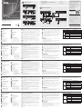
Revisione Hardware
Vista anteriore CE820L
1
Porta RS-232
2
Link LED
3
LED accensione
Vista posteriore CE820L
4
Connettore d'alimentazione
5
Porta HDBaseT Out
6
Porta Ethernet
7
Porta HDMI In
8
Porta USB Tipo B
9
Audio Out
10
Audio In
11
Interruttori DIP Modo Long Reach
e F/W aggiornamento
Vista anteriore CE820R
1
Porta RS-232
2
Pulsante Wake Up PC
3
LED Video Out
4
Link LED
5
LED accensione
Vista posteriore CE820R
6
Connettore d'alimentazione
7
Porta HDBaseT In
8
Porta Ethernet
9
Porta HDMI Out
10
Porte USB Tipo-A
11
Audio Out
12
Audio In
13
Interruttori DIP Modo Long Reach e
F/W aggiornamento
Nota: L’interruttore F/W Upgrade
(Aggiornamento FW) è riservato
per l’assistenza tecnica.
Se si desidera eseguire un
aggiornamento del fi rmware,
contattare il proprio rivenditore.
B
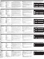
Installazione dell'hardware
Prima di procedere con l'installazione, assicurarsi che tutte le apparecchiature
da collegare siano spente; fare riferimento allo schema di installazione sopra
riportato e procedere come segue:
1
Collegare le spine audio del cavo KVM fornito in dotazione alle porte Audio
In e Audio Out del CE820L. Collegare l'altra estremità del cavo alle porte
Audio In e Audio Out del computer locale.
2
Collegare il connettore USB del cavo KVM in dotazione alla porta USB Tipo
B del CE820L. Collegare l'altra estremità del cavo a una porta USB di tipo A
del computer locale.
3
Collegare il connettore HDMI del cavo KVM in dotazione alla porta HDMI
In del CE820L. Collegare l' altra estremità del cavo alla porta HDMI del
computer locale.
4
Collegare un' estremità di un cavo Ethernet alla porta HDBaseT Out del
CE820L, e l' altra alla porta HDBaseT In del CE820R.
5
Inserire uno degli adattatori di alimentazione in dotazione in una fonte di
alimentazione, quindi collegare il cavo di alimentazione dell' adattatore
nella presa Power Jack del CE820L.
6
Utilizzare un cavo HDMI per collegare la porta HDMI Out sul CE820R al
monitor.
7
Collegare i dispositivi USB (mouse, tastiera, ecc.) alle rispettive porte USB
del CE820R.
8
Collegare il microfono e gli altoparlanti alle rispettive porte audio del
CE820R.
9
Per accedere a LAN o WAN, utilizzare un cavo Ethernet per collegare la
porta Ethernet del CE820L al computer, quindi utilizzare un altro cavo
Ethernet per collegare la porta Ethernet del CE820R a uno switch Ethernet.
10
Inserire il secondo adattatore di alimentazione (in dotazione con questo
pacchetto) in una fonte di alimentazione, quindi collegare il cavo di
alimentazione dell' adattatore alla presa di alimentazione del CE820R.
11
Per utilizzare il pulsante Wake Up PC, collegare la porta RS-232 del CE820L
al computer locale.
12
Per controllare il computer locale con un dispositivo seriale, collegare la
porta RS-232 del CE820L al computer locale, come illustrato nel passaggio
11, e collegare un controllore hardware/software alla porta RS-232 del
CE820R.
13
Se si desidera estendere il video fi no a 150 m con risoluzione 1080p,
posizionare il pulsante LONG REACH su ON.
Funzionamento
Montaggio in rack
Per comodità e fl essibilità, è possibile mostrare il CE820 sui rack del sistema.
Fare come segue per installare l’unità su rack:
1. Avvitare la staffa di montaggio nella parte superiore o inferiore dell' unità
utilizzando le viti fornite nel kit di montaggio.
2. Fissare la staffa nella posizione più comoda del rack.
Nota: Le viti rack non sono fornite in dotazione. Si consiglia di utilizzare viti
Phillips M5 ad incasso.
CE820 USB HDMI HDBaseT 2.0 KVM Extender
www.aten.com
Display LED e stato del sistema
LED Display LED Stato del sistemo
Alimentazione Verde acceso Il sistema sta ricevendo energia.
Link
Arancione acceso
Il collegamento tra CE820L e CE820R è
stabile.
Spento
Il collegamento tra CE820L e CE820R
spento.
Lampeggia
arancione
Il segnale di trasmissione HDBaseT è
instabile.
Video Out
Arancione acceso
Il display video è normale e protetto con
HDCP.
Lampeggia
arancione
Il display video è normale ma non protetto
con HDCP.
Spento Il video non viene visualizzato.
Nota: Il LED Video Out è disponibile solo sul CE820R.
A
Revisión del hardware
Vista frontal del CE820L
1
Puerto RS-232
2
LED de conexión
3
LED de alimentación
Vista posterior del CE820L
4
Conector de alimentación
5
Puerto de salida HDBaseT
6
Puerto Ethernet
7
Puerto de entrada HDMI
8
Puerto USB Tipo B
9
Salida de audio
10
Entrada de audio
11
Conmutadores DIP de actualización
modo largo alcance y F/W
Vista frontal del CE820R
1
Puerto RS-232
2
Pulsador reactivación del PC
3
LED de salida de vídeo
4
LED de conexión
5
LED de alimentación
Vista posterior del CE820R
6
Conector de alimentación
7
Puerto de entrada HDBaseT
8
Puerto Ethernet
9
Puerto de salida HDMI
10
Puerto USB Tipo A
11
Salida de audio
12
Entrada de audio
13
Conmutadores DIP de actualización
modo largo alcance y F/W
Nota: El interruptor de actualización
del F/W está reservado para
el soporte técnico. Si desea
actualizar el fi rmware, póngase
en contacto con su distribuidor.
B
Instalación del hardware
Antes de continuar con la instalación, asegúrese de que todo el equipo que se
va a conectar esté apagado; luego consulte el diagrama de instalación anterior
y haga lo siguiente:
1
Del juego de cables del KVM suministrado, conecte las clavijas de audio a
los puertos de entrada de audio y salida de audio del CE820L. Enchufe el
otro extremo del cable en los puertos de entrada de audio y salida de audio
del equipo local.
2
Del juego de cables del KVM suministrado, enchufe el conector USB al
puerto USB tipo B del CE820L. Enchufe el otro extremo del cable a un
puerto USB de tipo A en el equipo local.
3
Del juego de cables KVM suministrado, enchufe el conector HDMI al puerto
de entrada HDMI en el CE820L. Enchufe el otro extremo del cable en el
puerto HDMI del equipo local.
4
Conecte un extremo de un cable Ethernet en el puerto de salida HDBaseT
del CE820L, y el otro en el puerto de entrada HDBaseT del CE820R.
5
Enchufe uno de los adaptadores de corriente suministrados en una fuente
de alimentación; luego conecte el cable de alimentación del adaptador en
la toma de corriente del CE820L.
6
Utilice un cable HDMI para conectar el puerto de salida HDMI situado en el
CE820R a su monitor.
7
Conecte los dispositivos USB (ratón, teclado, etc.), en sus respectivos
puertos USB en el CE820R.
8
Conecte el micrófono y altavoces, en sus respectivos puertos de audio en el
CE820R.
9
Para obtener acceso a LAN o WAN, utilice un cable Ethernet para conectar
el puerto Ethernet del CE820L al ordenador, y luego use otro cable
Ethernet para conectar el puerto Ethernet del CE820R a un conmutador
Ethernet.
10
Conecte el segundo adaptador de alimentación (suministrado con este
paquete) a una fuente de alimentación; luego, conecte el cable de
alimentación del adaptador a la toma del CE820R.
11
Para usar la función reactivar PC, conecte el puerto RS-232 del CE820L en
el ordenador local.
12
Para controlar el ordenador local con un dispositivo serie, conecte el puerto
RS-232 del CE820L al ordenador local, como se muestra en el paso 11,
y conecte un controlador de hardware/software al puerto RS-232 del
CE820R.
13
Si desea extender el vídeo hasta 150m con una resolución de 1080p,
coloque el interruptor LONG REACH en la posición ON.
Funcionamiento
Montaje en rack
Para comodidad y fl exibilidad, el CE820 se pueden montar en racks del
sistema. Para montar una unidad en un rack, haga lo siguiente:
1. Utilizando los tornillos incluidos en el kit de montaje, atornille el soporte de
montaje en la parte superior o inferior de la unidad.
Extensor CE820 USB HDMI HDBaseT 2.0 KVM
www.aten.com
2. Atornille el soporte en cualquier lugar conveniente en el bastidor.
Nota: Los tornillos del rack no se proporcionan. Es recomendable utilizar
tornillos de estrella (Phillips) M5 de cabeza avellanada.
Pantalla LED y estado del sistema
LED Vista de los LEDs Estado del sistema
Alimentación Luz verde El sistema recibe alimentación.
Conexión
Luz naranja
La conexión entre el CE820L y el CE820R es
estable.
Desactivado
La conexión entre el CE820L y el CE820R
está desactivada.
Parpadea en
naranja
La transmisión de la señal del HDBaseT es
inestable.
Salida de
vídeo
Luz naranja
La pantalla de vídeo es normal y segura con
HDCP.
Parpadea en
naranja
La pantalla de vídeo es normal pero no
segura con HDCP.
Desactivado El vídeo no aparece.
Nota: El LED de salida de vídeo sólo está disponible en el CE820R.
A
Hardware Übersicht
CE820L – Ansicht von vorne
1
RS-232 Anschluss
2
Link LED
3
Netz-LED
CE820L – Ansicht von hinten
4
Netzbuchse
5
HDBaseT Ausgang
6
Ethernet-Port
7
HDMI Eingang
8
USB Typ-B Port
9
Audio-Ausgang
10
Audio-Eingang
11
Langstreckenmodus und F/
W-Aktualisierung DIP-Schalter
CE820R – Ansicht von vorne
1
RS-232 Anschluss
2
Drucktaste zur PC-Reaktivierung
3
Video Ausgang LED
4
Link LED
5
Netz-LED
CE820R – Ansicht von hinten
6
Netzbuchse
7
HDBaseT-Eingang
8
Ethernet-Port
9
HDMI Ausgang
10
USB Typ-A Ports
11
Audio-Ausgang
12
Audio-Eingang
13
Langstreckenmodus und F/
W-Aktualisierung DIP-Schalter
Hinweis: Der Schalter zur F/
W-Aktualisierung ist dem
technischen Support
vorbehalten. Wenden Sie sich
an Ihren Händler, falls Sie
eine Firmware-Aktualisierung
durchführen möchten.
B
Hardwareinstallation
Bevor Sie mit der Einrichtung fortfahren, vergewissern Sie sich, dass alle
anzuschließenden Geräte ausgeschaltet sind. Beachten Sie anschließend die
Installationsdiagramme weiter oben und führen Sie die folgenden Schritte aus:
1
Verbinden Sie die Audiostecker des mitgelieferten KVM-Kabelsets mit
dem Audio-Eingang und Ausgang des CE820L. Verbinden Sie das andere
Kabelende mit dem Audio-Eingang und Ausgang am lokalen Computer.
2
Verbinden Sie die Audiostecker des mitgelieferten KVM-Kabelsets mit dem
USB-Typ-B-Port des CE820L. Verbinden Sie das andere Kabelende mit
einem USB-Typ-A-Port am lokalen Computer.
3
Verbinden Sie die HDMI-Stecker des mitgelieferten KVM-Kabelsets mit dem
HDMI-Eingang des CE820L. Verbinden Sie das andere Kabelende mit dem
HDMI-Port am lokalen Computer.
4
Verbinden Sie ein Ende eines Ethernet-Kabels mit dem HDBaseT-Ausgang
am CE820L und das andere mit dem HDBaseT-Eingang am CE820R.
5
Verbinden Sie eines der mitgelieferten Netzteile mit einer Steckdose.
Schließen Sie dann das Netzkabel des Netzteils am Netzanschluss des
CE820L an.
6
Verbinden Sie den HDMI-Ausgang am CE820R über ein HDMI-Kabel mit
Ihrem Monitor.
7
Schließen Sie die USB-Geräte (Maus, Tastatur usw.) an den entsprechenden
USB-Ports am CE820R an.
8
Schließen Sie das Mikrofon und die Lautsprecher an die entsprechenden
Audioanschlüsse am CE820R an.
9
Um Zugriff auf LAN oder WAN zu erhalten, verbinden Sie den Ethernet-Port
des CE820L über ein Ethernet-Kabel mit dem Computer und verbinden Sie
den Ethernet-Port des CE820R über ein weiteres Ethernet-Kabel mit einem
Ethernet-Switch.
10
Verbinden Sie das zweite Netzteil (mitgeliefert) mit einer Steckdose.
Schließen Sie dann das Netzkabel des Netzteils am Netzanschluss des
CE820R an.
11
Um die Drucktaste zur PC-Reaktivierung zu verwenden, verbinden Sie den
RS-232 Port am CE820L mit dem lokalen Computer.
12
Um den lokalen Computer mit einem seriellen Gerät zu steuern, verbinden
Sie den RS-232 Port am CE820L mit dem lokalen Computer, wie in
Abbildung 11 gezeigt, und verbinden Sie einen Hardware/Software
Controller mit dem RS-232 Port am CE820R.
13
Wenn Sie die Videoreichweite bei einer Aufl ösung von 1080p auf bis zu
150 m erweitern möchten, schalten Sie den LANGSTRECKEN-Schalter EIN.
Bedienung
Rack-Montage
Aus Komfort- und Flexibilitätsgründen kann der CE820 an Systemracks montiert
werden. Gehen Sie zur Montage eines Gerätes in einem Rack wie folgt vor:
1. Befestigen Sie die Montagehalterung mit den im Montageset enthaltenen
Schrauben im oberen oder unteren Bereich des Gerätes.
2. Befestigen Sie die Halterung mittels Schrauben an einer geeigneten Stelle
im Rack.
CE820 USB HDMI HDBaseT 2.0 KVM Extender
www.aten.com
Hinweis: Rackschrauben sind nicht im Lieferumfang enthalten. Wie
empfehlen, vertiefte M5-Phillips-Schrauben zu verwenden.
LED-Display und Systemstatus
LED LED-Display Systemstatus
Betrieb Leuchtet grün Das System erhält Strom.
Verbindung
Leuchtet orange
Die Verbindung zwischen dem CE820L und
CE820R ist stabil.
Aus
Die Verbindung zwischen dem CE820L und
CE820R ist deaktiviert.
Blinkt orange Die HDBaseT Signalübertragung ist instabil.
Video
Ausgang
Leuchtet orange
Die Videoanzeige ist normal und mit HDCP
gesichert.
Blinkt orange
Die Videoanzeige ist normal, aber nicht mit
HDCP gesichert.
Aus Das Video wird nicht angezeigt.
Hinweis: Die LED für den Video-Ausgang ist nur am CE820R verfügbar.
A
Présentation du matériel
Vue de devant du CE820L
1
Port RS-232
2
LED Link (Liaison)
3
LED d'alimentation
Vue de derrière du CE820L
4
Prise d'alimentation
5
Port de sortie HDBaseT
6
Port Ethernet
7
Port d'entrée HDMI
8
Port USB Type B
9
Sortie audio
10
Entrée audio
11
Mode longue portée et commutateurs
DIP de mise à niveau du F/W
Vue de devant du CE820R
1
Port RS-232
2
Bouton poussoir de réveil PC
3
LED de sortie vidéo
4
LED Link (Liaison)
5
LED d'alimentation
Vue de derrière du CE820R
6
Prise d'alimentation
7
Port d’entrée HDBaseT
8
Port Ethernet
9
Port de sortie HDMI
10
Ports USB Type A
11
Sortie audio
12
Entrée audio
13
Mode longue portée et commutateurs
DIP de mise à niveau du F/W
Remarque : Le commutateur de
mise à niveau du F/W
est réservé à l’assistance
technique. Si vous voulez
faire une mise à niveau
du microprogramme,
contactez votre revendeur.
B
Installation matérielle
Avant de procéder à l'installation, assurez-vous que tout l'équipement à
connecter est éteint; puis reportez-vous au schéma d'installation ci-dessus et
procédez comme suit :
1
Connectez les fi ches audio du jeu de câbles KVM fourni aux ports d'entrée
audio et de sortie audio du CE820L. Branchez l'autre extrémité du câble
aux ports d'entrée audio et de sortie audio de l'ordinateur local.
2
Connectez le connecteur USB du jeu de câbles KVM fourni au port USB
Type B du CE820L. Branchez l'autre extrémité du câble à un port USB Type
A de l'ordinateur local.
3
Connectez le connecteur HDMI du jeu de câbles KVM fourni au port
d'entrée HDMI du CE820L. Branchez l'autre extrémité du câble au port
HDMI de l'ordinateur local.
4
Branchez une extrémité d'un câble Ethernet au port de sortie HDBaseT du
CE820L, et l'autre extrémité au port d'entrée HDBaseT du CE820R.
5
Branchez l'un des adaptateurs d'alimentation fournis à une source
d'alimentation ; puis branchez le câble d'alimentation de l'adaptateur à la
prise d'alimentation du CE820L.
6
Utilisez un câble HDMI pour raccorder le port de sortie HDMI du CE820R à
votre moniteur.
7
Branchez les périphériques USB (souris, clavier, etc.), à leurs ports USB
respectifs sur le CE820R.
8
Branchez le microphone et des enceintes à leurs ports audio respectifs sur
le CE820R.
9
Pour accéder au LAN ou au WAN, utilisez un câble Ethernet pour connecter
le port Ethernet du CE820L à l'ordinateur, puis utilisez un autre câble
Ethernet pour connecter le port Ethernet du CE820R à un commutateur
Ethernet.
10
Branchez le second adaptateur d'alimentation (fourni dans l’emballage)
à une source d'alimentation ; puis branchez le câble d'alimentation de
l'adaptateur à la prise d'alimentation du CE820R.
11
Pour utiliser le bouton-poussoir de réveil PC, connectez le port RS-232 du
CE820L à l'ordinateur local.
12
Pour contrôler l'ordinateur local avec un périphérique série, connectez le
port RS-232 du CE820L à l'ordinateur local, comme illustré à l'étape 11, et
connectez un contrôleur matériel/logiciel au port RS-232 du CE820R.
13
Si vous souhaitez prolonger la vidéo jusqu'à 150 m avec une résolution de
1080p, activez le commutateur REACH LONG (Longue portée).
Fonctionnement
Montage en rack
Pour plus de commodité et de fl exibilité, le CE820 peut être monté sur des
racks système. Pour monter une unité en rack, effectuez ce qui suit :
1. À l'aide des vis fournies dans le Kit de montage, vissez le support de
montage en bas et en haut de l’appareil.
2. Vissez le support dans un quelconque emplacement pratique sur le rack.
Remarque : Les vis de rack ne sont pas fournies. Nous vous conseillons
d'utiliser des vis cruciformes M5 à tête fraisée.
Répéteur KVM USB HDMI HDBaseT 2.0 CE820
www.aten.com
Affi chage LED et état du système
LED Affi chage LED État du système
Alimentation S'allume en vert Le est alimenté.
Liaison
S'allume en
orange
La connexion entre le CE820L et le CE820R
est stable.
Éteint
La connexion entre le CE820L et le CE820R
est désactivée.
Clignote en
orange
La transmission du signal HDBaseT est
instable.
Sortie vidéo
S'allume en
orange
L'affi chage vidéo est normal et sécurisé avec
HDCP.
Clignote en
orange
L'affi chage vidéo est normal mais pas sécurisé
avec HDCP.
Éteint La vidéo ne s'affi che pas.
Remarque : La LED de sortie vidéo est uniquement disponible sur le CE820R.
A
Hardware Review
CE820L Front View
1
RS-232 Port
2
Link LED
3
Power LED
CE820L Rear View
4
Power Jack
5
HDBaseT Out Port
6
Ethernet Port
7
HDMI In Port
8
USB Type B Port
9
Audio Out
10
Audio In
11
Long Reach Mode and F/W
Upgrade DIP Switches
CE820R Front View
1
RS-232 Port
2
Wake Up PC Pushbutton
3
Video Out LED
4
Link LED
5
Power LED
CE820R Rear View
6
Power Jack
7
HDBaseT In Port
8
Ethernet Port
9
HDMI Out Port
10
USB Type A Ports
11
Audio Out
12
Audio In
13
Long Reach Mode and F/W
Upgrade DIP Switches
Note: The F/W Upgrade switch is
reserved for technical support. If
you would like to do a fi rmware
upgrade, please contact your
dealer.
B
Hardware Installation
Before you proceed with the setup, make sure that all the equipment to be
connected is powered off; then refer to the installation diagram above, and do
the following:
1
Connect the audio plugs of the supplied KVM cable set to the Audio In and
Audio Out ports on the CE820L. Plug the other end of the cable into the
Audio In and Audio Out ports on the local computer.
2
Connect the USB connector of the supplied KVM cable set to the USB Type
B Port on the CE820L. Plug the other end of the cable into a USB Type A
port on the local computer.
3
Connect the HDMI connector of the supplied KVM cable set to the HDMI In
Port on the CE820L. Plug the other end of the cable into the HDMI port on
the local computer.
4
Plug one end of an Ethernet cable into the HDBaseT Out Port on the
CE820L, and the other into the HDBaseT In Port on the CE820R.
5
Plug one of the supplied power adapters into a power source; then plug
the adapter's power cable into the CE820L's Power Jack.
6
Use an HDMI cable to connect the HDMI Out Port on the CE820R to your
monitor.
7
Plug the USB devices (mouse, keyboard, etc.), into their respective USB
ports on the CE820R.
8
Plug the microphone and speakers, into their respective audio ports on the
CE820R.
9
To gain access to LAN or WAN, use an Ethernet cable to connect the
Ethernet Port of the CE820L to the computer, and then use another
Ethernet cable to connect the Ethernet Port of the CE820R to an Ethernet
switch.
10
Plug the second power adapter (supplied with this package) into a power
source; then plug the adapter's power cable into the CE820R's Power Jack.
11
To use the Wake Up PC Pushbutton, connect the RS-232 Port on the
CE820L to the local computer.
12
To control the local computer with a serial device, connect the RS-232 Port
on the CE820L to the local computer, as illustrated in step 11, and connect
a hardware/software controller to the RS-232 Port on the CE820R.
13
If you want to extend the video up to 150 m with 1080p resolution, put
the LONG REACH switch to ON.
Operation
Rack Mounting
For convenience and fl exibility, the CE820 can be mounted on system racks.
To rack mount a unit, do the following:
1. Using the screws provided in the Mounting Kit, screw the mounting bracket
into the top or bottom of the unit.
2. Screw the bracket into any convenient location on the rack.
Note: Rack screws are not provided. We recommend that you use M5 Phillips
recessed screws.
B
Hardware Installation
© Copyright 2017 ATEN
®
International Co., Ltd.
ATEN and the ATEN logo are trademarks of ATEN International Co., Ltd. All rights reserved. All
other trademarks are the property of their respective owners.
Part No. PAPE-1223-J90G Printing Date: 11/2017
USB HDMI HDBaseT 2.0 KVM Extender
Quick Start Guide
CE820
CE820 USB HDMI HDBaseT 2.0 KVM Extender
www.aten.com
ATEN VanCryst
™
LED Display and System Status
LED LED Display System Status
Power Lights green The system is receiving power.
Link
Lights orange
The connection between the CE820L and
CE820R is stable.
Off
The connection between the CE820L and
CE820R is off.
Flashes orange The HDBaseT signal transmission is unstable.
Video Out
Lights orange
The video display is normal and secured with
HDCP.
Flashes orange
The video display is normal but not secured
with HDCP.
Off The video is not displayed.
Note: The Video Out LED is only available on the CE820R.
Package Contents
1 CE820L USB HDMI HDBaseT 2.0 KVM Extender (Local Unit)
1 CE820R USB HDMI HDBaseT 2.0 KVM Extender (Remote Unit)
1 HDMI KVM Cable Set
2 Power Adapters
2 Mounting Kits
8 Foot Pads
1 User Instructions
Support and Documentation Notice
All information, documentation, fi rmware,
software utilities, and specifi cations
contained in this package are subject to
change without prior notifi cation by
the manufacturer.
To reduce the environmental impact of our
products, ATEN documentation and software
can be found online at
http://www.aten.com/download/
Technical Support
www.aten.com/support
이 기기는 업무용(A급) 전자파적합기기로서 판매자 또는
사용자는 이 점을 주의하시기 바라며, 가정외의 지역에
서 사용하는 것을 목적으로 합니다.
Scan for
more information
EMC Information
FEDERAL COMMUNICATIONS COMMISSION INTERFERENCE
STATEMENT:
This equipment has been tested and found to comply with the limits
for a Class A digital device, pursuant to Part 15 of the FCC Rules.
These limits are designed to provide reasonable protection against
harmful interference when the equipment is operated in a commercial
environment. This equipment generates, uses, and can radiate radio
frequency energy and, if not installed and used in accordance with
the instruction manual, may cause harmful interference to radio
communications. Operation of this equipment in a residential area
is likely to cause harmful interference in which case the user will be
required to correct the interference at his own expense.
FCC Caution: Any changes or modifi cations not expressly approved by
the party responsible for compliance could void the user's authority to
operate this equipment.
Warning: Operation of this equipment in a residential environment
could cause radio interference.
Suggestion: Shielded twisted pair (STP) cables must be used with the
unit to ensure compliance with FCC & CE standards.
This device complies with Part 15 of the FCC Rules. Operation is subject
to the following two conditions: (1) this device may not cause harmful
interference, and (2) this device must accept any interference received,
including interference that may cause undesired operation.
21 3 4 5
1 2 3
4 5 6 8 9
10
1310 11 12
7
11
6 7 8 9
CE820L Front View
CE820L Rear View
CE820R Front View
CE820R Rear View
Local PC
CE820L Rear View
CE820R Rear View
5
10
6
7
8
13
4
Internet/
LAN
9
3 12
9
11
12
A
Hardware Review
La pagina sta caricando ...
-
 1
1
-
 2
2


ATEN CE820 Guida Rapida
- Tipo
- Guida Rapida
- Questo manuale è adatto anche per
in altre lingue
- English: ATEN CE820 Quick start guide
- français: ATEN CE820 Guide de démarrage rapide
- español: ATEN CE820 Guía de inicio rápido
- Deutsch: ATEN CE820 Schnellstartanleitung
- русский: ATEN CE820 Инструкция по началу работы
- português: ATEN CE820 Guia rápido
- 日本語: ATEN CE820 クイックスタートガイド