
Brooks
®
2500 Series Flowmeters
Installation and Operation Manual
X-VA-2500-Series-eng
Part Number: 541B165AAG
November, 2016
Brooks
®
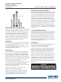
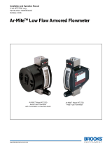
Models 2510, 2520, 2530 & 2540
Acrylic block flowmeters are available in various sizes
and ranges, with direct reading scales in both SAE and
SI units for air and water. For other gases or liquids,
special scales can be provided. If you use this meter
with fluids other than air or water, please consult
chemical compatibility data for possible effects on the
meter. These meters are manufactured of durable
acrylic and if properly installed and maintained, will
provide long-term trouble-free operation.
UNPACKING
Precautions have been taken to prevent any damage
from occurring during shipment. However, if the meter
is received damaged, report it to the carrier
immediately. Before installing, verify that you have the
model and flow range required.
INSTALLATION
The Model 2510, 2520 & 2530 meters are supplied
with 5/8" or 7/8" hex’s on the inlet and outlet fittings.
When installing 1/8-27 MNPT or ¼-18 MNPT fittings
into the meter, place the appropriate size wrench on
the hex to prevent the inlet/ outlet fitting from rotating.
Torque only to 60 in-lbs. Failure to do so will cause the
fitting to rotate, and may damage the meter body,
causing leaks and/or meter failure.
The Model 2540 meters are supplied with round 1-11 ½
FNPT inlet and outlet fittings. When installing the
meter, securely hold the meter’s fittings from rotating
while connecting the flow lines.
Use pipe thread sealant or Teflon
®
tape to ease
installation and provide a better seal.
These meters are supplied with #10-32 threaded
inserts for mounting. When installing, use slotted
screws and torque to a maximum of 35 in-lbs.
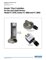
Mounting dimensions are shown in Figures 1 & 2.
ACHIEVING ACCURATE FLOWRATES
To obtain an accurate flowrate, the float must be read
at the position indicated on the meter. If the meter uses
a ball float, the flowrate is determined by reading the
center of the ball. Additionally, the flowmeter should be
installed in a manner, which minimizes both external
vibrations and internal flow variations. Special care
should be taken so that the connections to the meter’s
inlet and outlet fittings do not overly restrict the liquid or
gas flow being metered. This could result in a reduced
flow volume, preventing the meter from reaching its
maximum flowrate. Furthermore, internal pressures
could be affected, which can cause inaccurate flow
readings. On start-up, slowly purge any fluid trapped
in the meter.
CLEANING AND DISASSEMBLY
Occasional cleaning may be required if dirt appears in
the flow tube or if float movement becomes restricted.
To clean, remove the top plug and remove the float.
Wash the tapered hole and top plug with a mild liquid
detergent and soft brush. Rinse all parts with clean
water and dry thoroughly with clean air or nitrogen. Do
not use solvents to clean this meter as they will attack
the acrylic and destroy the meter.
REASSEMBLY
Check to make sure that all parts are clean and dry. To
lubricate the O-rings, apply a small amount of
halocarbon grease prior to reassembly.
If applicable, reinstall the rod guide assembly into the
flowmeter body. Make sure the rod guide is seated
firmly in the body of the meter for a Standard Back
meter or in the inlet fitting of the Inline meter. (For
meters with valves, it will be necessary for the rod
guide to pass through the slot in the valve tip.) To allow
proper use of the valve, do not tighten the valve tip
completely on the valve stem. Reinstall the top plug or
the outlet fitting, making sure that the rod guide is
properly aligned. Tighten top plug until it’s flush with
top of acrylic body. Exceeding this may damage the
meter body.
2500 Series

Brooks
®
2500 Series Flowmeters
Installation and Operation Manual
X-VA-2500-Series-eng
Part Number: 541B165AAG
November, 2016
Model 2540-S or V
E
D
2
/
1
B
C
A
F
8
/
1
Ê */
ÓÊ*>Viî
£äÎÓÊ/Ài>`i`
ÃiÀÌÃÊÓÊ*>Viî
Ê
Ê
Ê
Ê
A
B
£äÎÓÊ/Ài>`i`
ÃiÀÌÃÊÎÊ*>Viî
£¸Ê */ÊÉ"
iVÌÃ
£ä
£
⁄
2
ÓÈÇ®
£
Î
⁄
{
{{°x®
£
£
⁄
n
Ón°È®
{
£
⁄
2
££{®
Î
ÇÈ°Ó®
£Î
£
⁄
2
Î{ή
2
xä°n®
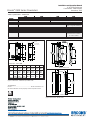
Dimensions - Inches (MM)
Model A B C D E F G
2510 4” 3” 1” 1-5/8” 1-3/16” 1-1/8” 1/8”
(102) (76.2) (25.4) (41.3) (30.2) (28.6) FNPT
2520 6-1/2” 5-1/2” 1-3/8” 3-1/2” 1-1/2” 1-1/8” 1/8”
(165) (140) (34.9) (88.9) (38.10) (28.6) FNPT
2530* 6-5/8” 5-1/2” 1-1/8” 3-1/2” 1-1/2” 1-3/8” 1/4”
(168) (140) (28.6) (88.9) (38.1) 34.9) FNPT
* Does not include 1/8” back plate
Model 2540-I
TRADEMARKS
Brooks........................................................... Brooks Instrument, LLC
All other trademarks are the property of their respective owners.
Table 1 Specifications - 2500 Series
Figure 1 Dimensions - Model 2510, 2520 & 2530
Figure 2 Dimensions - Model 2540
25102510
25102510
2510
25202520
25202520
2520
25302530
25302530
2530
25402540
25402540
2540
AccuracyAccuracy
AccuracyAccuracy
Accuracy ±5% full scale ±3% full scale ±2% full scale
FloatsFloats
FloatsFloats
Floats Black Glass, 316 Stainless Steel Stainless Steel
BodyBody
BodyBody
Body Clear Acrylic
SealsSeals
SealsSeals
Seals Buna-N O-rings with Brass fittings; Viton
®
O-rings with 303 Stainless Steel fittings Buna-N O-rings w/Brass or PVC fittings
Viton O-rings w/Stn Stl fittings
PressurePressure
PressurePressure
Pressure 100 PSIG Max.
TemperatureTemperature
TemperatureTemperature
Temperature 150°F/65°C Max.
FittingsFittings
FittingsFittings
Fittings Brass, 303 Stainless Steel PVC FNPT Pipe Connections (Std.)
ValvesValves
ValvesValves
Valves Brass or Stainless Steel Integral Valve on "V" models
Inline Gate Valve is available
for "S and I" models
CertificationsCertifications
CertificationsCertifications
Certifications International Calibration Certificate (ICC); Pressure Equipment Directive (97/23/EC); RoHS
-
 1
1
-
 2
2


Brooks 2500 Custom Solutions Istruzioni per l'uso
- Tipo
- Istruzioni per l'uso
- Questo manuale è adatto anche per
in altre lingue
Documenti correlati
-
 Brooks 1358 Istruzioni per l'uso
-
 Brooks 1350G/1355G Istruzioni per l'uso
-
 Brooks 3750C Istruzioni per l'uso
-
 Brooks 5700 Istruzioni per l'uso
-
 Brooks QMBC2 / QMBM2 / QMBC3 / QMBM3 / QMBC4 / QMBM4 Istruzioni per l'uso
-
Brooks 4850 / 4860 Istruzioni per l'uso
-
 Brooks 4860 Istruzioni per l'uso
-
 Brooks FC8744 / FC8800 / FC8900 Istruzioni per l'uso


