ProLights LUMIPIX15IP Manuale utente
- Categoria
- Stroboscopi
- Tipo
- Manuale utente

USER MANUAL
MANUALE UTENTE
EN - IT
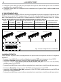
LINEAR LED BATTEN
LUMIPIX15IP

All rights reserved by Music & Lights S.r.l. No part of this instruction manual may be
reproduced in any form or by any means for any commercial use.
In order to improve the quality of products, Music&Lights S.r.l. reserves the right to modify the
characteristics stated in this instruction manual at any time and without prior notice.
All revisions and updates are available in the ‘manuals’ section on site www.musiclights.it
REV.001-09/17

1
LUMIPIX15IP
Packing content
• LUMIPIX15IP
• Mount bracket (2pc.)
• Power cable
• User manual
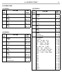
TABLE OF CONTENTS
Safety
General instructions
Warnings and installation precautions
1 Introduction
1. 1 Description
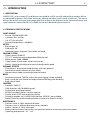
1. 2 Technical specications
1. 3 Operating elements and connections
2 Installation
2. 1 Mounting
3 Functions and settings
3. 1 Operation
3. 2 Basic
3. 3 Menu structure
3. 4 DMX mode
3. 5 DMX conguration
3. 6 Linking
3. 7 DMX Addressing
3. 8 Static mode
3. 9 DMX control
3. 10 Auto Show
3. 11 Dimmer
3. 12 Master/Slave mode
3. 13 White calibration
3. 14 Wireless settings
3. 15 Display settings
3. 16 Information
3. 17 Factory reload
3. 18 Connection of the DMX line
3. 19 Costruction of DMX termination
4 Maintenance
4. 1 Maintenance and cleaning the unit
4. 2 Fuse replacement
4. 3 Trouble shooting
2
2
3
3
5
6
7
7
8
9
9
9
10
10
11
14
14
14
14
14
15
15
15
16
16
17
17
17

LUMIPIX15IP
2
SAFETY
General instruction
• The products referred to in this manual conform to the European Community Directives and are there-
fore marked with .
• The unit is supplied with hazardous network voltage (230V~). Leave servicing to skilled personnel only.
Never make any modications on the unit not described in this instruction manual, otherwise you will
risk an electric shock.
• Connection must be made to a power supply system tted with ecient earthing (Class I appliance ac-
cording to standard EN 60598-1). It is, moreover, recommended to protect the supply lines of the units
from indirect contact and/or shorting to earth by using appropriately sized residual current devices.
• The connection to the main network of electric distribution must be carried out by a qualied electrical
installer. Check that the main frequency and voltage correspond to those for which the unit is designed
as given on the electrical data label.
• This unit is not for home use, only professional applications.
• Never use the xture under the following conditions:
- in places subject to vibrations or bumps;
- in places with a temperature of over 45 °C.
• Make certain that no inammable liquids, water or metal objects enter the xture.
• Do not dismantle or modify the xture.
• All work must always be carried out by qualied technical personnel. Contact the nearest sales point for
an inspection or contact the manufacturer directly.
• If the unit is to be put out of operation denitively, take it to a local recycling
plant for a disposal which is not harmful to the environment.
Warnings and installation precautions
• If this device will be operated in any way dierent to the one described in this manual, it may suer
damage and the guarantee becomes void. Furthermore, any other operation may lead to dangers like
short circuit, burns, electric shock, etc.
• Before starting any maintenance work or cleaning the projector, cut o power from the main supply.
• Always additionally secure the projector with the safety rope. When carrying out any work, always com-
ply scrupulously with all the regulations (particularly regarding safety) currently in force in the country
in which the xture’s being used.
• Install the xture in a well ventilated place.
• Keep any inammable material at a safe distance from the xture.
• Shields, lenses or ultraviolet screens shall be changed if they have become damaged to such an extent
that their eectiveness is impaired.
• The lamp (LED) shall be changed if it has become damaged or thermally deformed.
• Never look directly at the light beam. Please note that fast changes in lighting, e. g. ashing light, may
trigger epileptic seizures in photosensitive persons or persons with epilepsy.
• Do not touch the product’s housing when operating because it may be very hot.
WARNING! Before carrying out any operations with the unit, carefully read this instruction
manual and keep it with cure for future reference. It contains important information about
the installation, usage and maintenance of the unit.

3
LUMIPIX15IP
- 1 - INTRODUCTION
1.1 DESCRIPTION
LUMIPIX15IP is a tour-ready LED pixel batten conceived to be fully versatile and perform outdoor, deliver-
ing advanced brightness and colour mixing by oering individual pixel control of each cell. The robust
die-cast aluminium structure with omega quick locksocket on thebracket and the waterproof power and
signal connector make LUMIPIX15IP suitable for the most demanding environments.
1.2 TECHNICAL SPECIFICATIONS
LIGHT SOURCE
• Source: 15x10W RGBW LEDs
• Luminous ux: 3587lm
• Lux: 4771lux @3m full
• Source life expectancy: >30.000 h
OPTICS
• Beam angle: 16°
• Field angle: 30°
• Additional optics: Magnetic Frost holder on board
COLOUR SYSTEM
• Colour mixing: RGBW/FC
• CTC: CTC control through independent DMX channel
• White presets: 2800-10’000K
• Colour wheel: virtual colour wheel with presets
• Macros: several pre-build pixel macros with adjustable speed
DYNAMIC EFFECTS
• Pixel patterns: pre-programmed dynamic and static patterns
• Static colour mode: selection of static colour
• Manual colour mode: manual adjustment of colour
BODY
• Hardware on-board: OMEGA sockets for quick rigging (clamp included)
• Body: sturdy die-cast aluminium body conceived for long-time durability
• Body colour: black
CONTROL
• Protocols: DMX512
• DMX channels: 4/6/10/60/65channel
• Pixel control: pixel2pixel control
• W-DMX: included, wireless solution receiver
• Display: black OLED high resolution display
• Firmware upgrade: yes, via USB-DMX interface (UPBOX1) not included
• Master/Slave: for synchronized operation of more units linked in a chain
ELECTRONICS
• Dimmer: linear 0~100% electronic dimmer
• Dimmer curves: 4 dierent dimming curves available
• Strobe / shutter: 0~30 Hz, electronic
• Battery backup: battery backup for user operation without connecting to the main power
• Operating temperature: -10° ~ +45°

LUMIPIX15IP
4
ELECTRICAL
• Power supply: 100-240V – 50/60Hz
• Power consumption (at 230V): 161W
• Power consumption (at 120V): 162W
• Output (at 230V): 23 units on a single power line
• Output (at 120V): 12 units on a single power line
PHYSICAL
• Cooling: natural cooling of the peculiar chassis and to absence of fans
• Sospension and xing: double hanging bracket suitable for safe hanging and for oor positioning
• Signal connection: Seetronic XLR 5p IN/OUT connectors
• Data connection: W-DMX OEM TRX
• Power connection: Seetronic powerCON waterproof IN/OUT connectors
• IP rating: 65 for outdoor installations
• Dimensions (WxHxD): 996x205x160mm
• Weight: 8.6kg
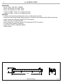
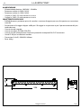
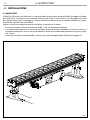
Fig.1Technical drawing
996
160
205

5
LUMIPIX15IP
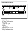
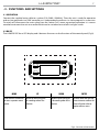
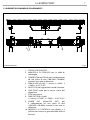
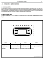
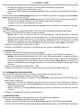
1.3 OPERATING ELEMENTS AND CONNECTIONS
Fig.2Rear panel
10
6
7 7
85
1
3
9
4
1
2 2
1. MOUNTING BRACKET.
2. LOCKING KNOB for the mounting bracket.
3. POWER IN (PowerCON IN): for connection to a
socket (100-240V~/50-60Hz) via the supplied
mains cable.
4. DMX IN (5-pole XLR):
1 = ground, 2 = DMX -, 3 = DMX +.
5. SAFETY RING to attach safety cable.
6. GND POINT grounding the xture to the earth.
7. HOLE for hook.
8. DMX OUT (5-pole XLR): 1 = ground, 2 = DMX-,
3 = DMX+, 4 N/C, 5 N/C.
9. POWER OUT (PowerCON OUT): power output
for connection of multiple units in series.
10. CONTROL PANEL with display and 4 button
used to access the control panel functions
and manage them

LUMIPIX15IP
6
- 2 - INSTALLATION
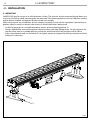
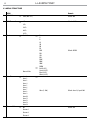
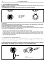
2.1 MOUNTING
LUMIPIX15IP may be set up on a solid and even surface. The unit can also be mounted upside down to a
cross arm. For xing, stable mounting clips are required. The mounting place must be of sucient stability
and be able to support a weight of 10 times of the unit’s weight.
When carrying out any installation, always comply scrupulously with all the regulations (particularly re-
garding safety) currently in force in the country in which the xture’s being used.
• Install the projector at a suitable location by means of the mounting bracket (1).
• Always additionally secure the projector with the safety rope from falling down. For this purpose, fas-
ten the safety rope at a suitable position so that the maximum fall of the projector will be 20 cm.
• Adjust the projector and use the knob (2) to slightly release or tighten the locking mechanism of the
bracket if is necessary.
Fig.3
1
2

7
LUMIPIX15IP
- 3 - FUNCTIONS AND SETTINGS
3.1 OPERATION
Connect the supplied main cable to a socket (110-240V~/50-60Hz). Then the unit is ready for operation
and can be operated via a DMX controller or it independently performs its show program in succession.
To switch o, disconnect the mains plug from the socket. For a more convenient operation it is recom-
mended to connect the unit to a socket which can be switched on and o via a light switch.
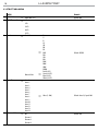
3.2 BASIC
The LUMIPIX15IP has a LED display and 4 buttons for access to the functions of the control panel (Fig.3).
MENU UP DOWN ENTER
Used to access the menu or
to return a previous menu
option
Button to select the values
in ascending order of the
function
Button to select the values
in descending order of the
function
Used to select and store the
current menu or conrm the
current function value or
option within a menu
Fig.4 - Functions of the buttons

LUMIPIX15IP
8
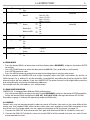
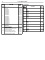
3.3 MENU STRUCTURE
MENU Remark
1 DMX Address
ð
Value (001-512) Default: 001
2 DMX Channel
ð
4 Ch Default: 10 CH
6 Ch
10 Ch
60 Ch
65 Ch
3 Static
ð
Fixed Color
ð
R
G
B
W
GB
RB
RG
RGB
RW
GW
BW
RGW
RBW
GBW
RGBW
Default: RGBW
Manual Color
ð
Red (0-255)
Green (0-255)
Blue (0-255)
White (0-255)
4 Auto Show
ð
Auto 1
Auto 2
Auto 3
Auto 4
Auto 5
Auto 6
Auto 7
Auto 8
Auto 9
Auto 10
Auto 11
Auto 12
Auto 13
Auto 14
ð
Value (1-100) Default: Auto 14; Speed:100
5 Dimmer Mode
ð
O Default: O
Dimmer 1
Dimmer 2
Dimmer 3

9
LUMIPIX15IP
3.4 DMX MODE
• Press the button MENU so many times until the display shows DMX ADDRESS, and press the button ENTER
to conrm.
• Press UP/DOWN button to select the desired value (001-512). Press and hold to scroll quickly.
• Press ENTER button to store.
• Press the MENU button to go back or to meet the waiting time to exit the setup menu.
To able to operate the LUMIPIX15IP with a light controller, adjust the DMX start address for the rst a
DMX channel. If e. g. address 33 on the controller is provided for controlling the function of the rst DMX
channel, adjust the start address 33 on the LUMIPIX15IP. The other functions of the light eect panel are
then automatically assigned to the following addresses.
An example with the start address 33 is shown below:
3.5 DMX CONFIGURATION
LUMIPIX15IP is equipped with dierent DMX conguration.
• Press the button MENU so many times until shows DMX CHANNEL, and press the button ENTER to conrm.
• Select the desired DMX conguration (4CH - 6CH - 10 CH - 60 CH - 65 CH ) through the buttons UP/DOWN.
The tables on page 14 indicate the operating mode and DMX value.
3.6 LINKING
Several units may be interconnected in order to control all further slave units to the same eect of the
master unit. Use standard DMX cables to daisy chain your units together via the DMX connector on the
rear of the units. For longer cable runs we suggest a terminator at the last xture (see page 12).
1. Connect the DMX OUT of the master unit via 3-pole XLR cable to the DMX IN of the rst slave unit.
2. Connect the DMX OUT of the rst slave unit to the DMX IN of the second slave unit, etc. until all units
are connected in a chain.
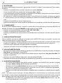
6 Master/Slave
ð
Master
Slave
Default: Slave
7 White Balance
ð
O
Default: O
Manual
ð
Red <125-255>
Green <125-255>
Blue <125-255>
White <125-255>
8 Wireless Setting
ð
Receive
ð
On
O
Default: O
Receive Reset
ð
No
Yes
Wireless To DMX
ð
No
Yes
9 Key Lock
ð
On
O
Default: On
10 Back Light
ð
On
10 s
20s
30 s
11 Information
ð
Fixture Hours < 9999H >
Version < V1.0 >
12 Resect Factory
ð
No
Yes

LUMIPIX15IP
10
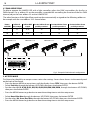
DMX Address: 60DMX Address: 42DMX Address: 33 DMX Address: 51
Fig.5 - Example 9 DMX channels conguration
. . . . . . . . . . . .
DMX512 Controller
3.7 DMX ADDRESSING
To able to operate the LUMIPIX15IP with a light controller, adjust the DMX start address for the rst a
DMX channel. If e. g. address 33 on the controller is provided for controlling the function of the rst DMX
channel, adjust the start address 33 on the LUMIPIX15IP.
The other functions of the light eect panel are then automatically assigned to the following addresses.
An example with the start address 33 is shown below:
3. 8 STATIC MODE
This xture has the ability to accept custom static color settings. Access these chases via the control panel
on the back of the xture.
• Press the button MENU so many times until the display shows STATIC, then press the button ENTER.
• Select Fixed Color through the buttons UP/DOWN, then press the button ENTER.
• Set the colors R, G, B, W, GB, RB, RG, RGB, RW, GW, BW, RGW, RBW, GBW, RGBW, through the buttons UP/DOWN,
then press the button ENTER.
• Press the MENU button to go back or to meet the waiting time to exit the setup menu.
• Select Manual Color Mixer through the buttons UP/DOWN, then press the button ENTER.
• Set the colors Red, Green, Blue, White, through the buttons UP/DOWN, then press the button ENTER.
• Press the MENU button to go back or to meet the waiting time to exit the setup menu.
Numero
canali DMX
Indirizzo di
start (esempio)
Indirizzo DMX
occupati
Prossimo indirizzo di start
possibile per unità n°1
Prossimo indirizzo di start
possibile per unità n°2
Prossimo indirizzo di start
possibile per unità n°3
6 33 33-38 39 45 51
10 33 33-42 43 53 63

11
LUMIPIX15IP
3. 9 DMX CONTROL
4 CANALI
MODE
FUNCTION DMX
Value
4 Ch
1
RED
0~100% 000 - 255
2
GREEN
0~100% 000 - 255
3
BLUE
0~100% 000 - 255
4
WHITE
0~100% 000 - 255
6 CANALI
MODE
FUNCTION DMX
Value
6 Ch
1
DIMMER
0~100% 000 - 255
2
RED
0~100% 000 - 255
3
GREEN
0~100% 000 - 255
4
BLUE
0~100%
000 - 255
5
WHITE
0~100%
000 - 015
016 - 255
6
STROBE
No Function
Strobe slow to fast
000 - 010
011 - 255
10 CANALI
MODE
FUNCTION DMX
Value
10 Ch
1
DIMMER
0~100% 000 - 255
2
RED
0~100% 000 - 255
3
GREEN
0~100% 000 - 255
4
BLUE
0~100% 000 - 255
5
WHITE
0~100% 000 - 255
6
STROBE
No Function
Strobe slow to fast
000 - 010
011 - 255
7
COLOR MACROS
No Function
R 100%, G 0~100%, B 0%
R 100%~0%, G 100%, B 0%
R 0%, G 100%, B 0~100%
R 0% G 100%~0% B 100%
R 0%~100% G 0% B 100%
R 100% G 0% B 100%~0%
R 100% G 0%~100% B 0%~100%
R 100%~0% G 100%~0% B 100%
R 100% G 100% B 100% W100%
Color1
Color2
Color3
Color4
Color5
Color6
Color7
Color8
Color9
Color10
Color11
000 - 010
011 - 030
031 - 050
051 - 070
071 - 090
091 - 110
111 - 130
131 - 150
151 - 170
171 - 200
201 - 205
206 - 210
211 - 215
216 - 220
221 - 225
226 - 230
231 - 235
236 - 240
241 - 245
246 - 250
251 - 255

LUMIPIX15IP
12
60 CANALI
MODE
FUNCTION DMX
Value
60 Ch
1
RED 1
0~100% 000 - 255
2
GREEN 1
0~100% 000 - 255
3
BLUE 1
0~100% 000 - 255
4
WHITE 1
0~100% 000 - 255
.............
57
RED 15
0~100% 000 - 255
58
GREEN 15
0~100% 000 - 255
59
BLUE 15
0~100% 000 - 255
60
WHITE 15
0~100% 000 - 255
MODE
FUNCTION DMX
Value
10 Ch
8
AUTO PROGRAM
No Function
Auto program 1
Auto program 2
Auto program 3
Auto program 4
Auto program 5
Auto program 6
Auto program 7
Auto program 8
Auto program 9
Auto program 10
Auto program 11
Auto program 12
Auto program 13
Auto program 14
000 - 010
011 - 027
028 - 044
045 - 061
062 - 078
079 - 095
096 - 112
113 - 129
130 - 146
147 - 163
164 - 180
181 - 197
198 - 214
215 - 231
232 - 255
9
AUTO SPEED
Auto Speed Slow to Fast 000 - 255
10
DIMMER SPEED MODE
Preset dimmer speed from display menu
Dimmer speed mode o
Dimmer speed mode1 (fast speed)
Dimmer speed mode2 (middle speed)
Dimmer speed mode3 (slow speed)
000 - 051
052 - 101
102 - 152
153 - 203
204 - 255

13
LUMIPIX15IP
65 CANALI
MODE
FUNCTION DMX
Value
65 Ch
1
RED 1
0~100% 000 - 255
2
GREEN 1
0~100% 000 - 255
3
BLUE 1
0~100% 000 - 255
4
WHITE 1
0~100% 000 - 255
.........
57
RED 15
0~100% 000 - 255
58
GREEN 15
0~100% 000 - 255
59
BLUE 15
0~100% 000 - 255
60
WHITE 15
0~100% 000 - 255
61
AUTO PROGRAM
No Function
Auto program 1
Auto program 2
Auto program 3
Auto program 4
Auto program 5
Auto program 6
Auto program 7
Auto program 8
Auto program 9
Auto program 10
Auto program 11
Auto program 12
Auto program 13
Auto program 14
000 - 010
011 - 027
028 - 044
045 - 061
062 - 078
079 - 095
096 - 112
113 - 129
130 - 146
147 - 163
164 - 180
181 - 197
198 - 214
215 - 231
232 - 255
62
AUTO SPEED
Auto Speed Slow to Fast 000 - 255
63
DIMMER
0~100% 000 - 255
65 CANALI
MODE
FUNCTION DMX
Value
65 Ch
64
STROBE
No Function
Strobe slow to fast
000 - 010
011 - 255
65
DIMMER SPEED MODE
Preset dimmer speed from display menu
Dimmer speed mode o
Dimmer speed mode1 (fast speed)
Dimmer speed mode2 (middle speed)
Dimmer speed mode3 (slow speed)
000 - 051
052 - 101
102 - 152
153 - 203
204 - 255

LUMIPIX15IP
14
3. 10 AUTO SHOW
This xture has a built-in automatic program. To access this, please see the below instructions:
• Press the button MENU so many times until shows P--, then press the button ENTER.
• Using UP/DOWN button, select one of the programs P1 - P14.
• Press the button ENTER to conrm.
• Press the button MENU until S-- appears on the display.
• Use the button UP/DOWN to select the auto programs speed S1 - S100 (slow-fast).
• Press the button ENTER save the setting.
3. 11 DIMMER
It is possible to change the parameter value in the following way:
• Enter in Dimmer mode to select specic dimming curve, press the button MENU so many times until
shows DIM MODE, and press the button ENTER to conrm.
• Press the button UP/DOWN to select OFF - DIM1 - DIM2 - DIM3.
• Press ENTER button to store.
• Press the MENU button to go back or to meet the waiting time to exit the setup menu.
3. 12 MASTER/SLAVE MODE
This mode will allow you to link up the units together without a controller. Choose a unit to function as the
Master. The unit must be the rst unit in line; other units will work as slave.
• Use standard DMX cables to daisy chain your units together via the DMX connector on the rear of the
units. For longer cable runs we suggest a terminator at the last xture (see page 13).
• Use any one of the standalone modes for the master unit.
• Set the slaves to the same DMX modes.
3. 13 WHITE CALIBRATION
• Press the button MENU then press the button UP/DOWN so many times until show WHITE CALIBRATION.
Press the button ENTER to conrm.
• Select the color Red, Green, Blue, White through the buttons UP/DOWN. Press the button ENTER to con-
rm.
• Set the value (125 - 255), using the buttons UP/DOWN.
• Continue until the desired setting is obtained.
• Press the MENU button to go back or to meet the waiting time to exit the setup menu.
3. 14 WIRELESS CONTROL SETTINGS
To change the settings of wireless control, proceed as follows:
• Press the ENTER button to access the main menu.
• Press the UP/DOWN button to scroll through the menu, select Wireless Setting, and press the ENTER but-
ton to enter the next menu.
• Press the UP/DOWN button to select the option proposed and press the ENTER button to conrm your
choice.
- Receive - Disable/enable the DMX signal cable. Select OFF to deactivate or ON to activate the func-
tion.
- Receive Reset - Reset the wireless connection of the unit. Select NO to deactivate or Yes to activate
the function.
• Press the ENTER button to conrm your choice.
• Press the LEFT button repeatedly to exit the menu and save changes.
To activate the Wireless to DMX function, use the UP/DOWN buttons to press the ENTER button until the
display shows Wireless Setting, then press the ENTER button.
• Select the Wireless to DMX function using the UP/DOWN buttons, then press the ENTER button.

15
LUMIPIX15IP
• To activate the mode use the UP/DOWN buttons and select the Yes option.
• Press the ENTER button to conrm the selection.
• Press the LEFT button to go back or wait a few seconds to exit the setup menu.
3.15 DISPLAY SETTINGS
You can change the following parameters related to the display, following the same procedure:
• Press the ENTER button to access the main menu.
• Press the UP / DOWN keys to scroll the menu, select the Setup icon, then press the ENTER button to
enter the next menu.
• Press UP / DOWN to scroll through the menu, then select UI Set, and press the ENTER button to enter
the next menu.
• Press UP / DOWN to scroll through the menu, and then select one of the following settings for the dis-
play and press the ENTER key to display it.
- Back Light - Backlight display Auto O. This feature allows you to automatically turn o the backlight
after a specied time that you can set using the arrow buttons. To have the display always on select
Always On or set a value of 01-99 min to turn o the display after the amount of time you choose.
- Key Lock - Lock keys. With this function, you can lock the buttons on the control panel. If this function
is activated, the keys are automatically locked. To disable or temporarily disable the key lock func-
tion, press the buttons in the following order to regain access to menu commands: UP, DOWN, LEFT,
RIGHT, ENTER. Select ON to activate or OFF to disable.
• Press the ENTER button to conrm your choice.
• Press the LEFT button repeatedly to exit the menu and save changes.
3.16 INFORMATION
To view all the information on the device, proceed as follows:
• Press the ENTER button to access the main menu.
• Press the UP/DOWN button to scroll the menu, select the icon Information, then press the ENTER button
to enter the next menu.
• Press the UP/DOWN button to scroll through the menu, then select one of the following information
and press the ENTER button to display it.
- Time Information - Through the Time Information function you can display the operating time of the
projector.
- Software Version - Through Software Version function you can display the currently installed software
version.
• Press the LEFT button repeatedly to exit the menu.
3. 17 FACTORY RELOAD
Select this function to restore the drive to default settings:
• To activate Factory Reload display press the button MENU so many times until shows Reset Factory,
and press the button ENTER to conrm.
• Press ENTER button to conrm the selection.
• Press the MENU button to go back or to meet the waiting time to exit from the setup menu automati-
cally.

LUMIPIX15IP
16
Fig.7
3.18 CONNECTION OF THE DMX LINE
DMX connection employs standard XLR connectors. Use shielded pair-twisted cables with 120Ω imped-
ance and low capacity.
The following diagram shows the connection mode:
ATTENTION
The screened parts of the cable (sleeve) must never be connected to the system’s earth, as this would
cause faulty xture and controller operation.
Over long runs can be necessary to insert a DMX level matching amplier.
For those connections the use of balanced microphone cable is not recommended because it cannot
transmit control DMX data reliably.
• Connect the controller DMX input to the DMX output of the rst unit.
• Connect the DMX output to the DMX input of the following unit. Connect again the output to the input
of the following unit until all the units are connected in chain.
• When the signal cable has to run longer distance is recommended to insert a DMX termination on the
last unit.
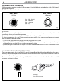
3.19 CONSTRUCTION OF THE DMX TERMINATION
The termination avoids the risk of DMX 512 signals being reected back along the cable when they reach-
es the end of the line: under certain conditions and with certain cable lengths, this could cause them to
cancel the original signals.
The termination is prepared by soldering a 120Ω 1/4 W resistor between pins 2 and 3 of the 5-pin male XLR
connector, as shown in gure.
Example:
5 pin XLR connector
Fig.6
DMX - OUTPUT
XLR socket
DMX - INPUT
XLR plug
Pin1 : GND - Shield
Pin2 : - Negative
Pin3 : + Positive
Pin4 : N/C
Pin5 : N/C

17
LUMIPIX15IP
- 4 - MAINTENANCE
4.1 MAINTENANCE AND CLEANING THE UNIT
• Make sure the area below the installation place is free from unwanted persons during setup.
• Switch o the unit, unplug the main cable and wait until the unit has cooled down.
• All screws used for installing the device and any of its parts should be tightly fastened and should not
be corroded.
• Housings, xations and installation spots (ceiling, trusses, suspensions) should be totally free from any
deformation.
• The main cables must be in impeccable condition and should be replaced immediately even when a
small problem is detected.
• It is recommended to clean the front at regular intervals, from impurities caused by dust, smoke, or
other particles to ensure that the light is radiated at maximum brightness. For cleaning, disconnect the
main plug from the socket. Use a soft, clean cloth moistened with a mild detergent. Then carefully wipe
the part dry. For cleaning other housing parts use only a soft, clean cloth. Never use a liquid, it might
penetrate the unit and cause damage to it.
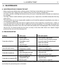
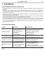
4.3 TROUBLESHOOTING
Problems Possible causes Checks and remedies
Fixture does not light up
• No mains supply
• Dimmer fader set to 0
• All color faders set to 0
• Faulty LED
• Faulty LED board
• Check the power supply voltage
• Increase the value of the dimmer channels
• Increase the value of the color channels
• Replace the LED board
• Replace the LED board
General low light intensity
• Dirty lens assembly
• Misaligned lens assembly
• Clean the xture regularly
• Install lens assembly properly
Fixture does not power up
• No power
• Loose or damaged power cord
• Faulty internal power supply
• Check for power on power outlet
• Check power cord
• Replace internal power supply
Fixture does not respond to DMX
• Wrong DMX addressing
• Damaged DMX cables
• Bouncing signals
• Check control panel and unit addressing
• Check DMX cables
• Install terminator as suggested
Contact an authorized service center in case of technical problems or not reported in the table can not be
resolved by the procedure given in the table.

REV.001-09/17
Music & Lights S.r.l. si riserva ogni diritto di elaborazione in qualsiasi forma delle presenti istruzioni per l’uso.
La riproduzione - anche parziale - per propri scopi commerciali è vietata.
Al ne di migliorare la qualità dei prodotti, la Music&Lights S.r.l. si riserva la facoltà di modicare, in
qualunque momento e senza preavviso, le speciche menzionate nel presente manuale di istruzioni.
Tutte le revisioni e gli aggiornamenti sono disponibili nella sezione 'Manuali' sul sito www.musiclights.it
La pagina si sta caricando...
La pagina si sta caricando...
La pagina si sta caricando...
La pagina si sta caricando...
La pagina si sta caricando...
La pagina si sta caricando...
La pagina si sta caricando...
La pagina si sta caricando...
La pagina si sta caricando...
La pagina si sta caricando...
La pagina si sta caricando...
La pagina si sta caricando...
La pagina si sta caricando...
La pagina si sta caricando...
La pagina si sta caricando...
La pagina si sta caricando...
La pagina si sta caricando...
La pagina si sta caricando...
La pagina si sta caricando...
La pagina si sta caricando...
-
 1
1
-
 2
2
-
 3
3
-
 4
4
-
 5
5
-
 6
6
-
 7
7
-
 8
8
-
 9
9
-
 10
10
-
 11
11
-
 12
12
-
 13
13
-
 14
14
-
 15
15
-
 16
16
-
 17
17
-
 18
18
-
 19
19
-
 20
20
-
 21
21
-
 22
22
-
 23
23
-
 24
24
-
 25
25
-
 26
26
-
 27
27
-
 28
28
-
 29
29
-
 30
30
-
 31
31
-
 32
32
-
 33
33
-
 34
34
-
 35
35
-
 36
36
-
 37
37
-
 38
38
-
 39
39
-
 40
40


ProLights LUMIPIX15IP Manuale utente
- Categoria
- Stroboscopi
- Tipo
- Manuale utente
in altre lingue
- English: ProLights LUMIPIX15IP User manual
Documenti correlati
-
ProLights 96x3W high power and portable outdoor wireless battery wash light Manuale utente
-
-
-
-
-
-
-
-
-