Blaupunkt HELSINKI RTM 127 Manuale del proprietario
- Tipo
- Manuale del proprietario

- 1 -
Sicherheitshinweise
Vor Einbau Ihres Autoradios die Einbau- und An-
schlußvorschriften lesen.
Für die Dauer der Montage und des Anschlusses
ist der Minuspol der Batterie abzuklemmen.
Hierbei sind die Sicherheitshinweise des Kfz-Her-
stellers (Airbag, Alarmanlagen, Bordcomputer,
Wegfahrsperren) zu beachten.
Beim Bohren von Löchern darauf achten, daß kei-
ne Fahrzeugteile (Batterie, Kabel, Sicherungska-
sten) beschädigt werden.
Der Querschnitt des Plus und Minuskabels darf
1,5 mm
2
nicht unterschreiten. Das Gerät ist mit ei-
ner Sicherung, 10 A flink, abgesichert.
Das Seitenteil des Autoradios wird im Betrieb sehr
heiß. Es ist darauf zu achten, daß keine Kabel am
Gehäuse anliegen.
In einigen Fahrzeugen liegt ein 20 poliger Stecker
im Einbauschacht. Dieser Stecker darf nicht am
Autoradio angeschlossen werden.
In allen Fahrzeugen darf der fahrzeugseitige 8 polige
+/- ISO-Stecker nicht direkt an Ihren Helsinki ange-
schlossen werden.
Immer Adapterkabel benutzen!
Achtung! Bei Falschanschluß erlöscht der Garantie-
anspruch!
Das Radiophone sollte nur vom Fachpersonal in Ihrem Kraftfahrzeug installiert und gewartet werden. Fehlerhafte
Installation oder Wartung kann gefährlich sein und zum Erlöschen der Garantie führen.
Wird das Fahrzeug nicht ausreichend gegen Hochfrequenz-Signale geschützt, können bei elektronischen Kraftstoffein-
spritz-Systemen, elektronischen ABS- Systemen, elektronischen Fahrgeschwindigkeitsreglern oder anderen elektroni-
schen Systemen Fehlfunktionen auftreten.
8 622 401 055/03.98St.
Helsinki RTM 127
7 647 982 010
Einbauanleitung (D) Seite 1
Fitting instructions (GB) page 8
Instructions de montage (F) page 11
Istruzioni di montaggio (I) pagina 14
Inbouwinstrukties (NL) pagina 17
Monteringsanvisninsida (S) sida 20
Instrucciones de montaje (E) página 23
Instruções de montagem (P) página 26

- 2 -
Anschlußvorbereitung
Der folgende Abschnitt gibt Ihnen eine kleine
Einbauübersicht.
Welche Autoradiokomponenten befinden sich in Ihrem
Fahrzeug?
Autoradio, Lautsprecher mit Verstärker (aktiv), oder ohne Ver-
stärker (passiv), Antenne mit oder ohne Verstärker, Motoranten-
ne, Scheibenantenne.
Mit welchen Steckverbindungen ist ein vorhandenes Ra-
dio adaptiert?
Sind es ISO-Norm Anschlüsse (würden mechanisch an Ihren
Helsinki passen) oder Kfz.-spezifische?
Wie groß ist der Querschnitt von eventuell vorhandenen Kabeln?
Fahrzeuge ohne Autoradios
Liegen bereits Lautsprecher und Stromkabel im Fahrzeug? Sind
es ISO-Norm Anschlüsse oder Kfz.-spezifische?
Wie groß ist der Querschnitt von eventuell vorhandenen Kabeln?
Wie sieht ein ISO-Norm Stecker aus?
Schauen Sie sich bitte die mitgelieferten Anschlußkabel an.
Beide sind mit ISO-Norm Steckern versehen. Am Plus/Minus-
Anschlußkabel sind die beiden roten Drähte und der braune
Draht mit 1,5 mm
2
Querschnitt versehen. Der orange und der-
gelb/grüne Draht haben einen Querschnitt von 1mm
2
.
ISO-Norm Stecker können je nach Kfz.-Hersteller
unterschiedliche Anschlußbelegungen haben!
Für die Dauer der Montage und des Anschlusses
ist der Minuspol der Batterie abzuklemmen.
Hierbei sind die Sicherheitshinweise des Kfz-Her-
stellers (Airbag, Alarmanlagen, Bordcomputer,
Wegfahrsperren) zu beachten.
• Strom-Anschluß
Anschluß an Fahrzeugseitige ISO-Norm Stek-
ker.
In allen Fahrzeugen darf der fahrzeugseitige 8 polige
+/- ISO-Stecker nicht direkt an Ihren Helsinki ange-
schlossen werden. Immer Adapterkabel benutzen.
Bei Falschanschluß erlöscht der Garantieanspruch!
Zur Vermeidung von elektrischen Fehlanschlüssen bei fahr-
zeug-seitigen ISO-Steckern ist das
Universal-ISO-Adapterka-
bel
(Best.- Nr. 7 607 621 126) für den Dauerplus, Minus, Plus
über Zündung, Beleuchtungsanschluß und Plus 12V Schaltaus-
gang für externe Komponenten z.B.: Motorantenne zu verwen-
den.
Zur Zeit können folgende Fahrzeuge mit ISO-Norm An-
schlüssen mit dem
Universal-ISO-Adapterkabel
adaptiert
werden
:
Alfa Romeo, Citroen, Fiat, Honda, Lancia, Merce-
des, Peugeot, Porsche, Renault, Skoda.
Achtung! Für andere Fahrzeuge mit ISO-Norm Anschlüssen ist
das Kfz.- spezifische Adapterkabel zu verwenden.
Es muß sichergestellt sein, daß der Radioanschluß im Auto
bereits werkseitig mit einer 10 A Sicherung abgesichert ist .
Strom-Anschluß an Kfz.-spezifische Stecker.
Ist Ihr Radioanschluß im Auto bereits werkseitig mit einer 10A
Sicherung abgesichert (siehe Bedienungsanleitung oder Si-
cherungskasten Ihres Kfz.), so benötigen Sie noch das Kfz.-
spezifische Adapterkabel und das Universal-Spannungs-
versorgungskabel welche im Fachhandel erhältlich sind (sie-
he Fig. 6, Seite 5).
Bei weniger als 10A Absicherung, muß wie unter "Anschluß in
Fahrzeugen ohne jegliche Vorrüstung" beschrieben eingebaut
werden.
Anschluß in Fahrzeugen ohne jegliche
Vorrüstung.
Bei Fahrzeugen ohne Autoradio- Vorrüstung oder zu geringen
Plus-Minus Kabelquerschnitten (< 1,5 mm
2
) ist das
beiliegende
ISO +/- Anschlußkabel
(zu erkennen am braunen, orangen,
gelb/grünen und zwei roten Kabeln) mit dem
Universal-Span-
nungsversorgungskabe
l (im Fachhandel erhältlich; Best.-
Nr. 7 607 884 093) zu verbauen (siehe Fig. 4, Seite 4).
• Lautsprecheranschluß
Lautsprecheranschluß an Fahrzeugseitige
ISO-Norm Stecker.
Bei dieser Anschlußart muß geklärt werden ob sie eine passive
oder aktive Lautsprechervorrüstung haben. Passiv entspricht;
Lautsprecher ohne eigenen Verstärker. Aktiv mit Verstärker.
Diese Info können Sie über Ihren Kfz.- oder Fachhändler bezie-
hen.
Bei einer passiven Vorrüstung (mit 4 Ohm Lautsprecher)
können Sie den im Kfz. befindlichen ISO- Stecker adaptieren.Bei
Bedarf mit ISO-Kabel (7 607 647 093) verlängern.
Für eine aktiv Vorrüstung können Sie über Ihren Fachhändler
für bestimmte Fahrzeuge entsprechende Adapterkabel bezie-
hen.
Lautsprecheranschluß in Fahrzeugen ohne
jegliche Vorrüstung.
Bei nachträglich eingebauten Lautsprechern verwenden Sie das
beigelegte
ISO-Lautsprecherkabel
. DieVerbindung zwischen
dem ISO-Lautsprecherkabel und den Lautsprechern können Sie
mit Lüsterklemmen (nicht im Lieferumfang enthalten) herstellen
(siehe Fig. 7, Seite 5).
• Antenneneinbau
Hier gibt es eine große Auswahl von Antennentypen. Inter-
essant wären z.B. Kombiantennen. Ihr Bosch-Händler wird
Sie gern beraten.
Radioantenne
Bei neueren vorgerüsteten Fahrzeugen z.B.: VW, Seat, Audi
wird die Versorgungsspannung für die Antenne über das Anten-
nenkabel zugeführt.(Siehe Bedienungsanleitung vom Kfz.) Soll
das Erstausrüstungsradio gegen ein handelsübliches Radio
ausgetauscht werden, so ist eine Antenneneinspeiseweiche
(Best.-Nr. 7 691 290 202) von Ihrem Fachhändler zu beziehen.
Antenneneinbau und Anschluß siehe Antenneneinbauanleitung.
Je nach vorhandenen Antennentyp muß evt. beiliegender An-
tennenadapter mit Halter verwendet werden (siehe Fig. 3a,
Seite 3).
Telefonantenne
Nach Einbau der Antenne den Anschluß am Radio handfest
anziehen, und noch eine
1
/4 Umdrehung mit einer Zange nach-
ziehen.
Hinweis: Die Telefonantenne muß mit mindestens 1m Ab-
stand zur Radioantenne verbaut werden. Die Telefonanten-
nenleitung darf nicht in die Nähe der Lautsprecherleitungen
verlegt werden.
• Autoradioeinbau
Das Autoradio wird in den vom Fahrzeughersteller vorgesehe-
nen Autoradioausschnitt eingebaut. Autoradioausschnitt freile-
gen (Ablagefach oder Blindblende ausclipsen) oder Autoradio-
ausschnitt auf 182 x 53 mm ausarbeiten.
Für Fahrzeuge mit abweichender Einbausituation liefert Blau-
punkt für die gängigsten Fahrzeuge fahrzeugspezifische Ein-
bausätze für 50 mm Geräte. Prüfen Sie daher, welche Einbau-
situation im Fahrzeug vorliegt, und verwenden Sie zum Einbau
gegebenenfalls einen fahrzeugspezifischen Einbausatz.
8 622 401 055

- 3 -
8 622 401 055
Fahrzeugseitiger Halterahmen oder Fernbedie-
nungen
Bei Fahrzeugen, die fahrzeugseitig mit einem Halterahmen
ausgerüstet sind (z. Z. Opel), muß der fahrzeugseitige Halterah-
men ausgebaut werden. Fahrzeugseitige Lenkradfernbedie-
nungen können bei einigen Fahrzeugen mit einem entsprechen-
den Interface adaptiert werden. Bitte beim Fachhänder informie-
ren.
Einbau der Halterung
Die zum Lieferumfang dieses Autoradios gehörende Halterung
ermöglicht den Einbau in Fahrzeugen mit DIN- Autoradioaus-
schnitt von 182 x 53 mm, 165 mm Einbauraum und einer Instru-
mententafeldicke im Bereich der Befestigungslaschen von 1 -
20 mm, siehe Fig. 1.
Halterung in den Ausschnitt schieben und prüfen, welche Befe-
stigungslaschen der Halterung mit einem Schraubendreher
umgebogen werden können (siehe Fig. 1 u. 2).
Hinweis: Möglichst alle Befestigunglaschen umbiegen.
Autoradioeinbau
Alle Stecker so weit in die Kammern einschieben, bis die
seitlichen Rastnasen einrasten.Das Autoradio von vorn in die
Halterung einsetzen. Durch sanften Druck auf beide Rahmenen-
den einschieben, bis die seitlichen Rastfedern rechts und links
arretieren (deutliches Knacken hörbar) (siehe Fig. 3).
Beim Einschub nicht auf Display, Knöpfe oder Schal-
ter drücken!
Autoradioausbau
Bügel links und rechts in die vorhandenen Löcher der Blende
stecken und so weit eindrücken, bis deutliches Knacken zu
hören ist (seitliche Federn entriegelt).
Gerät an den beiden Bügeln vorsichtig herausziehen. Jetzt
können die Anschlußkabel durch seitlichen Druck auf die jewei-
lige Rastnase herausgezogen werden (siehe Fig. 3).
Hinweis: Eingerastete Bügel können nur nach Herausziehen
des Gerätes entfernt werden.
Anschlußzeichnungen
Anschluß in Fahrzeugen ohne jegliche Vorrüstung .......Fig. 4
Strom-Anschluß an Fahrzeugseitige ISO-Norm SteckerFig. 5
Strom-Anschluß an Kfz.-spezifische Stecker. ................Fig. 6
Lautsprecheranschluß 4 AL (4 Ω/35 W)........................Fig. 7
LF = links vorn, RF = rechts vorn,
LR = links hinten, RR = rechts hinten.
Equalizer oder Amplifieranschluß (CINCH)....................Fig. 8
Anschluß mit Freisprechmikrofon..................................Fig. 9
Anschluß mit Telefonhörer (Handset 7 607 570 512) ..Fig. 10
Anschluß CD- Player CDC- A06/072 ............................Fig. 11
Anschluß IR- Fernbedienung RCT 07...........................Fig. 12
Anschluß CD-Player CDC-A05/071 ..............................Fig. 13
Anschluß CD-Player CDC-F05 .....................................Fig. 14
PIN 2
8 601 910 002
2
2
1
1
Fig.3
Fig.3a
Fig.2
Mitgelieferte Montage- und Anschlußteile - Supplied Mounting Hardware - Materiel de montage fourni - Ferretería de
montaje suministrada - Componenti di fissaggio comprese nella fornitura - Meegeleverde montagematerialen -
Medföljande monteringsdetaljer - Elementos de fixação fornecidos.
Radioantenne
15A
Universal-Spannungsversorgungskabel,Universal power
cable,Câble d‘alimentation électrique universel, Cavo di
adattamento universale, Universele voedingskabel, Universal-
spänningskabeln,cable de alimentación universal , comércio
especializado Nr. 7 607 884 093
53
182
165
8 601 310 742
1-20
Fig.1
Der Führungsbolzen wird mit oder ohne Distanzstück auf das
Schraubgewinde der Geräterückwand gesteckt.
Telefonantenne

- 4 -
Steuerkabel (Power Antenna +)
Das Steuerkabel ist der geschaltete Plusausgang für
externe Komponenten z.B.: Motorantenne,
(maximale Belastung < 150 mA).
Das Steuerkabel
nicht an Klemme 15 (Plus geschaltet) oder
Klemme 30 (Dauerplus) anschließen.
Externer Alarm
Anschluß an PIN 2 nur über ein Relais
(maximale Belastung < 100 mA). Dauer = 5 Klingeltöne
+12V
Plusanschluß (über Zündung geschaltet)
Wird das Pluskabel am Sicherungshalter (Kl.15) hinter
der Sicherung angeschlossen, so ist das Ein- und Aus-
schalten des Autoradios über Zündung möglich. Außer-
dem schaltet das Gerät zum Schutz der Batterie automa-
tisch nach einer Stunde aus.
" Zündtimer 00 " .Die Stunden-Logik wird
nicht aktiviert,
wenn Dauerplus (Kl.30) angeschlossen wird.
Masseanschluß (Ground)
Massekabel (min. Querschnitt 1,5 mm
2
) nicht am Minuspol
der Batterie anklemmen.
Massekabel zu einem geeigneten Massepunkt verlegen
(Karosserieschraube, Karosserieblech). Massekabel ab-
isolieren und Krallenkabelschuh anschlagen (ggf. nachlö-
ten). Kontaktfläche des Massepunktes metallisch blank
kratzen und mit Graphitfett einfetten (wichtig für gute Mas-
severbindung). Massekabel anschrauben.
Dauerplusanschluß (Kl.30 Batterie + 12 V)
Pluskabel (rot) mit starkem Querschnitt (min.1,5 mm
2
) zur
Batterie verlegen (Kabel nicht unmittelbar an Kabelbäumen
verlegen). Sicherungshalter zur Absicherung des Plus-
kabels anschließen und am Pluspol der Batterie anklem-
men.
per. +12V
Fig.4
8 604 390 045
Universal-
Spannungsversorgungskabel
7 607 884 093
rot
rot
braun
orange
gelb/grün
Beleuchtungsanschluß (Illumination) Beleuchtungs-
anschluß für Fahrzeuge mit regelbarer Instrumentenbe-
leuchtung (plusgeregelt). Bei nicht vorgerüsteten Fahr-
zeugen den Anschluß beim Kfz.-Händler erfragen.
8 622 401 055
< 1s
1
2
345
nur bei Zündung aus und aktivierten
externen Alarm
+12V
Relais
12V
Kl.15 +12V
10A

- 5 -
8 622 401 055
Fig. 5
gelb/yello/jaune
giallo/geel/gul
7 607 886 093
5 m
7 607 893 093
0,3 m
Fig. 8
7 607 621 126
+12V
+12V
10A
Fig. 7
10A
Fig. 6
Kfz.-spezifisches Adapterkabel, adapterwiring
adaptateur, cavo di adattamento
adapterkabel, adapterkabelkabe
el cable adaptador, cabo de adaptação
Universal-Spannungsversorgungskabel, connection wiring câble de
raccordement, câble de raccordement, aansluitkabel anslutningskabel, cable
de conexión, cabo de ligação
(7 607 884 093)
per.+12V
Kl.15
per.+12V
Fig. 4
!
15A
1
2
V
12V
Antenne
10A
8 604 390 045
RR
RF
LF
LR
+
-
+
-
+
-
+
-
8 604 390 087
10A
LR
RR
RF
LF

- 6 -
Fig. 10
Fig. 9
+12V/ kl15
per.+12V
+12V
rt
15A
12V
br
3A
CDC A06
A072
10
10
Fig. 11
8 619 000 200 5m
1
2
7 607 884 093
8 622 401 055
10A
10
10
3
Einbau in Spiegelnähe,
positionning near the interior miror,
Position près de la miroire intèrieure,
Monteras i närheten av spegeln.
Instalación cerca del espejo.

- 7 -
Fig. 13
Fig. 14
CDC A05
A071
Power/Bus 5m
7 607 889 093
7 607 647 093
7 607 884 093
2
1
3
+12V
per.+12V
+12V
15A
12V
10A
Fig. 12
8 622 401 055Änderungen vorbehalten!
CDC
10A

- 8 -
Safety notes
Before starting to mount your car radio, read the mounting and
connection instructions carefully.
Disconnect the vehicle battery’s negative terminal before making
connections.
Be sure to observe the safety notes of the automobile manufacturer
(airbags, alarm systems, on-board computers, immobilisers).
Before drilling holes, look to see what is on the other side - making
holes into the battery, wiring looms or fuse box is not recommen-
ded!
The positive lead used must have a cross-section of at least 1.5
mm
2
. The set is protected by a quick-acting 10 A fuse.
During operation of the unit, the set’s side wall may heat up
considerably.
Be sure to keep all wires away from hot parts of the housing.
In some vehicles you will find a 20-pin connector pre-fitted in the
dashboard’s installation space. This connector must not be used
for connecting the car radio!
You must not connect your Helsinki car radio to an existing
8-pin +/- ISO connector in your car. Always use the adapter
cable. Our warranty shall be vain if the connection is made
inadequately.
Preparing for the installation
The following section gives you a brief instal-
lation overview.
What car radio components are installed in your car?
Car radio, loudspeakers with amplifier (active) or without amplifier
(passive), antenna with or without amplifier, power antenna, window
antenna.
What adapters are used for the existing car radio?
Are there standard ISO connectors (which are compatible with your
Helsinki car radio) or car specific adapters?
What cross-section do the existing cables have?
Vehicles without car radio
Are loudspeakers and power cables installed in your car? Are standard
ISO connectors or car-specific adapters used?
What cross-section do the existing cables have?
What does an standard ISO connector look like?
Take a look at the cables included in the delivery. Both cables are
equipped with standard ISO connectors. The two red wires and the
brown wire of the positive and negative cable have a cross-section of 1.5
mm
2
. The orange and the yellow/green wire have a cross-section of 1
mm
2
.
The pinning of standard ISO connectors may differ accor-
ding to auto manufacturer.
While installing and mounting this equipment, you must
disconnect the negative terminal of the battery.
You must also comply with all safety instructions given by
the auto manufacturer (airbag, alarm system, board com-
puter, vehicle immobilizer).
• Connecting the power supply
Connection to standard ISO adapter installed in
your car.
You must not connect your Helsinki car radio to an existing
8-pin +/- ISO connector in your car. Always use the adapter
cable. Our warranty shall be vain if the connection is made
inadequately.
To prevent inadequate electrical connection in vehicles equipped with
ISO connectors, use the universal ISO adapter cable (P/N 7 607 621 126)
for constant power connection, negative connection, the positive con-
nection via the ignition, illumination and +12V switching output for
external components such as a power antenna.
At present, the following vehicles with standard ISO connectors
can be adapted using the universal ISO adapter cable: Alfa Romeo,
Citroen, Fiat, Honda, Lancia, Mercedes, Peugeot, Porsche, Renault,
Skoda.
Attention! For all other car models with standard ISO connector use the
car-specific adapter cable. Make sure that the existing car radio terminal
in the your car is protected by a 10 A fuse.
Power supply to vehicle-specific connectors
If the existing car radio terminal in your car is protected by a 10 A fuse (see
operating instructins or fuse box in your car), you only need to have the
car-specific adapter cable which is available at your dealer (see Fig.
6,page 5).
If the fuse value is less than 10 A, follow the steps described under
„Connection in vehicles without car radio wiring“.
Connection in vehicles without car radio wiring
If your car is not equipped with any car radio wiring or if the cross-section
of the existing positive/negative wires is insufficient (< 1.5 mm
2
), install
the enclosed ISO +/- cable (one brown, orange, yellow/green wire and
two red wires) together with the universal power supply cable (available
at your specialist dealer; P/N 7 607 884 093); see Fig. 4 (page 10).
• Connecting the loudspeakers
Loudspeaker connection to the standard ISO adap-
ter in your car
For this type of connection, first check whether you have passive or active
loudspeakers installed in your car. Active loudspeakers have an integra-
ted amplifier, passive loudspeakers do not have an amplifier. For more
information contact your car dealer or audio dealer.
If your car is equipped with passive loudspeakers (4 ohms) you can adapt
the ISO connector installed in your car. Use ISO cable (7 607 647 093)
to prolong your wiring. If active loudspeakers are installed in your car, you
can order the necessary adapter cable for various vehicles from your
specialist dealer.
Loudspeaker connection in vehicles without
loudspeaker wiring
For subsequently installed loudspeakers use the ISO loudspeaker cable
included in the delivery. Use cable connectors to link the ISO loudspea-
ker cable to the loudspeakers (not included in the delivery); see Fig. 7
(page 5).
8 622 401 055
Helsinki RTM 127
Fittings instructions
GB
Have the Radiphone installed in your vehicle and serviced by a trained service technician only. Faulty installation or
servicing can be dangerous and will result in the expiry of your guarantee.
If the vehicle is not adequately shielded against radio frequency signals, electronic injector systems, electronic ABS
systems, electronic cruise control systems or other electronic equipment may experience malfunctions.

- 9 -
• Installing the antenna
A wide range of different antennas is available in the market.
Combination antennas, for example, are an
interesting solution.
For more information please contact your Bosch dealer.
Radio antenna
In new vehicles with antenna prefitting, e.g. VW, Seat, Audi, the power
is supplied to the antenna via the antenna cable (see user manual of your
car). If you wish to replace the original equipment for a conventional car
radio, you need to purchase an antenna duplexer (P/N 7 691 290 202)
from your specialist dealer. Information on how to install and connect
your antenna is provided in the antenna installation instructions. Accor-
ding
to the antenna type you wish to install, it may be necessary to use the
antenna adapter with holder included in the delivery (see Fig. 3a).
Telephone antenna
The Telephone ariel (GSM) shold be installed to 1m- distance from radio
one. After you have installed the antenna, tighten the connection at your
car radio by hand und add another 1/4 rotation using pliers.
Note: Make sure the telephone wires are not routed close to the
loudspeaker wiring.
• Installing the car radio
Install your car radio into the car radio compartment of your car.Uncover
the radio compartment (remove the shelf or the dummy panel) or cut the
car radio slot to a size of 182 x 53 mm. For the most common cars with
deviating installation places Blaupunkt offers specific 50-mm car radio
installation kits. Therefore, please check the car radio installation place
in your car. If required, use one of our car-specific installation kits.
Car radio sleeve or remote control installed in your
car
If your vehicle is equipped with a specific car radio mounting sleeve (e.g.
Opel), it is necessary to remove the original sleeve. Steering wheel
remote controls installed in some vehicles can be adapted by means of
an interface. Contact your specialist dealer for more information.
Installing the mounting sleeve
The mounting sleeve included with this car radio is designed for instal-
lation in vehicles with standard DIN installation compartment measuring
182 x 53 mm, 165 mm installation depth and a dashboard thickness of
1 to 20 mm in the area of the tab fasteners (see Fig. 1).Insert the car radio
into the sleeve and check which tabs on the sleeve can be bent with the
help of a screwdriver (see Fig. 1 and 2).
Note: Bend as many taps as possible.
Installing the car radio
Insert all connectors into the chambers until the side catches engage.
Place the car radio in the front of the sleeve and push it in gently on both
ends of the sleeve until the left and right side springs snap into place (you
will hear an audible click), see Fig. 3.
Advantage! Do not push on the display, keys or switches!
Removing the car radio
Insert the handles into the holes in the panel on the left and right side of
the radio and push them in until you hear an audible click (the side springs
unlock). Gently pull the unit out using both handles (see Fig. 3).
Note: Handles which have snapped into place can only be removed
after you have pulled the radio out of the compartment.
Connecting diagrams
Vehicles without car radio prefitting (page 10) .......................... Fig. 4
Power supply to standard ISO connectors (page 5) ................. Fig. 5
Power supply to car-specific connectors (page 5) .................... Fig. 6
PIN 2
Mounting and connection hardware included in the delivery
Loudspeaker connection 4x 4Ω/35 watts (page 5) ................... Fig. 7
Equaliser or amplifier connection (page 5) ............................... Fig. 8
LF = left front, RF = right front
LR = left rear, RR = right rear
Handsfree microphone connection (page 6) ............................. Fig. 9
Handset connection (7 607 570 512) (page 6) ......................... Fig. 10
CD player connection (CDC A06/072) (page 6)........................ Fig. 11
IR remote control connection (RCT 07) (page 7) ...................... Fig. 12
CD player connection (CDC-A05/071) (page 7) ....................... Fig. 13
CD player connection (CDC-F05) (page 7)............................... Fig. 14
8 622 401 055
Fig.3a
Fig.2
Radio antenna
Telephon antenna
8 601 910 002
2
2
1
1
Fig.3
53
182
165
8 601 310 742
1-20
Fix the guide pin with or without spacer
on the stud at the car radio rear side.

- 10 -
Control cable (power antenna +)
The control cable is the positive switching output for external
components, e.g. power antenna (max. load < 150 mA).
Do not connect the control cable to terminal 15 (positive switching
line) or to terminal 30 (constant power).
Constant power terminal (terminal 30 battery +12V)
Lay the positive cable (red) with large cross-section (min. 1.5
mm
2
) to the battery (do not route any cable close to a wire
harness). Attach the fuse holder to protect the positive cable and
connect it to the positive terminal of the battery.
Ground connection
Do not connect the ground cable (min. cross-section 1.5 mm
2
) to
the negative terminal of the battery.Connect the ground cable to
a suitable ground spot (car body screw, car body sheet). Strip off
the insulation at the end of the ground cable and attach a spade
lug (resolder if necessary).
Scratch the contact point for the ground down to the bare metal
and grease it with anti-seize graphite petroleum (important for
good grounding). Screw down the ground cable.
Illumination connection
Connection for vehicles with adjustable instrument illumination
(pulse controlled).
Positive connection (switched via ignition)
If you connect the positive cable of the fuse holder
(terminal 15) behind the fuse, you can turn the car radio on
and off with the ignition. Also, your car radio will turn off
automatically after one hour to protect the battery.
„Ignition timer 00“. The 1-hour logic will not be activated,
if the constant power wire (terminal 30) is connected.
< 1s
1
2
345
External alarm
only if ignition is off and external alarm activated
Connection to pin 2 only via relay(max. load < 100 mA). Duration
= 5 ringing signals
Universal power cable
(7 607 884 093)
orange
red
brown
red
yellow/green
Fig. 4
8 622 401 055This information is subject to change without notice!
+12V
Relais
12V
Kl.15 +12V
10A

- 11 -
Helsinki RTM 127
Instructions de montage
F
• Préliminaires au branchement
La section suivante vous donne un bref aperçu
des conditions de montage.
Quels éléments d‘autoradio se trouvent dans votre
véhicule?
Autoradio, haut-parleurs avec ampli (actif) ou sans ampli (pas-
sif). Antenne avec ou sans ampli, antenne de moteur, antenne
de vitre.
Au moyen de quels connecteurs votre auto radio
est-il branché?
Est-ce que ce sont des connexions de norme ISO (s‘adapteraient
mécaniquement à votre autoradio Helsinki) ou spécifiques au
véhicule ?
Quelles sont les dimensions de la section des câbles éventuel-
lement utilisés ?
Véhicules sans autoradio
Est-ce qu‘il y a déjà des haut-parleurs et des câbles électriques
dans votre véhicule ? Est-ce que ce sont des connexions de
norme ISO ou spécifiques au véhicule ?
Quelles sont les dimensions de la section des câbles éventuel-
lement utilisés ?
Quelle est l‘apparence d‘une fiche de norme ISO ?
Regardez de près les câbles de branchement fournis ? Ces deux
câbles sont munis de fiches de norme ISO. Les deux fils rouges
et le fil marron du câble de branchement +/- ont une section de
1,5 mm
2
. Le fil orange et le fil jaune/vert a une section de 1 mm
2
.
En fonction du constructeur automobile, les fiches
de norme ISO peuvent avoir différentes affectations
de connexion.
Ne confiez les travaux d’installation et d’entretien du radiophone dans le véhicule qu’au personnel qualifié. Des travaux d’installation
ou d’entretien non effectués correctement risquent d’être dangereux et peuvent avoir pour conséquence l’expiration de la garantie.
Si le véhicule n’est pas protégé suffisamment contre des signaux H.F., des erreurs de fonctionnement risquent de se présenter aux
systèmes électroniques d’injection de carburant, aux systèmes ABS électroniques, aux réglages électroniques de la vitesse de
roulement ou à d’autres systèmes électroniques.
Indications de sécurité
Veuillez lire les instructions de montage et de raccordement
avant de monter votre autoradio.
Débrancher le pôle négatif de la batterie pendant les opéra-
tions de montage et de branchement.
Prendre note des indications de sécurité du fabricant du
véhicule (airbag, alarmes, ordinateur de bord, dispositifs de
blocage des roues).
En perçant des trous, veiller à ce que les éléments du
véhicule (batterie, câble, boîte à fusibles) ne soient pas
endommagés.
La section du câble positif ne doit pas être inférieure à 1,5
mm
2
.
L’appareil est protégé par un coupe-circuit à action instan-
tanée de 10 A.
Dans tous les véhicules, la fiche ISO +/- 8 pôles,
présentes dans le véhicule ne doit pas être branchée
directement sur votre Helsinki. Il faut toujours utili-
ser un câble adaptateur. En cas de mauvais branche-
ment, la garantie s‘annule !
Le pôle (-) de la batterie doit être débranché pour la
durée du montage et du branchement.
Les consignes de sécurité du constructeur automo-
bile (airbag, alarmes, ordinateur de bord, système de
blocage) doivent être ici observées.
• Branchement électrique
Connexion aux fiches de norme ISO présentes dans le
véhicule.
Dans tous les véhicules, la fiche ISO +/- 8 pôles,
présentes dans le véhicule ne doit pas être branchée
directement sur votre Helsinki. Il faut toujours utili-
ser un câble adaptateur. En cas de mauvais branche-
ment, la garantie s‘annule !
Pour éviter toute erreur de branchement électrique pour les
fiches ISO dont le véhicule est équipé, il faut utiliser le
câble
adaptateur ISO universel
(réf. 7 607 621 126) pour le (+)
permanent, (-), (+) via l‘allumage, la connexion d‘éclairage et (+)
12 V de sortie pour les éléments externes tels que l‘antenne de
moteur.
Les véhicules offrant des connexions de norme ISO qui
peuvent être adaptées au câble adaptateur ISO universel
sont les suivants : Alfa Romeo, Citroen, Fiat, Honda, Lancia,
Mercedes, Peugeot, Porsche, Renault et Skoda.
Attention ! Pour les autres véhicules munis de connexions de
norme ISO, l‘utilisation du câble adaptateur spécifique au véhi-
cule est obligatoire.
Il est important de s‘assurer que la connexion l‘autoradio dans le
véhicule ait été protégée au préalable en usine par un fusible de
10 A.
Branchement électrique aux fiches spécifiques au
véhicule.
Si la connexion de l‘autoradio a été déjà protégée en usine par
un fusible de 10 A (cf. notice d‘emploi ou boîte à fusibles de votre
véhicule), vous n‘avez besoin que d‘un câble adaptateur spéci-
fique au véhicule, disponible dans le commerce (cf. Fig. 6,
page 5).
En cas de protection inférieure à 10 A, le montage s‘effectuera
comme décrit sous «Branchement dans les véhicules sans
prédispositif».
Branchement dans les véhicules sans prédispositif
Pour les véhicules ne disposant pas de prédispositif d‘autoradio
ou offrant des sections de câble +/- trop faibles (<1,5 mm
2
), le
câble de branchement +/- de norme ISO
fourni (muni d‘un fil
marron, orange, jaune/vert, et de deux fils rouges) doit être
raccordé au
câble d‘alimentation électrique universel
(dispo-
nible chez les revendeurs spécialisés; réf. 7 607 884 093) (cf.
Fig. 4, page 13).
8 622 401 055

- 12 -
• Branchement des haut-parleurs
Connexion des haut-parleurs aux fiches de norme
ISO du véhicule
Pour ce type de branchement, il est important de savoir si votre
véhicule dispose d‘un prédispositif de haut-parleurs passif ou
actif. Passif correspond aux haut-parleurs équipés d‘un amplifi-
cateur propre. Actif sans amplificateur. Pour cela, renseignez-
vous auprès de votre concessionnaire automobile ou de votre
revendeur.
Si le prédispositif est de type «passif» (haut-parleurs de 4
ohms), vous pouvez adapter la fiche ISO se trouvant dans le
véhicule. Si nécessaire, la prolonger par un câble ISO (réf. 7 607
647 093).
Si le prédispositif est de type «actif», vous pouvez faire
l‘acquisition de câbles adaptateurs correspondants pour cer-
tains véhicules chez votre revendeur.
Branchement de haut-parleurs dans les véhicules
sans prédispositif
Si des haut-parleurs ont été montés ultérieurement, utilisez le
câble de haut-parleur ISO fourni. Vous pouvez raccorder le
câble de haut-parleur ISO aux haut-parleurs au moyen de
dominos (non fournis) (cf. Fig. 7, page 5).
• Montage de l‘antenne
Vous trouvez ici un grand choix de types d‘antenne. Les
antennes telles les antennes combinées sont particulière-
ment intéressantes. Pour tout renseignement, n‘hésitez
pas à consulter votre revendeur agréé Bosch.
Antenne d‘auto radio
Pour les véhicules récents prééquipés, tels que VW, Seat, Audi,
la tension d‘alimentation pour l‘antenne est conduite via le câble
d‘antenne (cf. notice d‘emploi du véhicule). Si vous souhaitez
remplacer l‘autoradio de première monte par un autoradio
courant disponible dans le commerce, il vous faudra vous
procurer un déflecteur d‘alimentation d‘antenne (réf. 7 691 290
202) en vente chez votre revendeur. Pour le montage de
l‘antenne et le branchement, consultez la notice de montage
d‘antenne. En fonction du type d‘antenne utilisé, un adaptateur
d‘antenne avec support sera éventuellement requis
(cf. Fig. 3a,page 3).
Antenne de téléphone
Le montage de l‘antenne effectué, serrer le connecteur de
l‘autoradio à la main et la resserrer encore d‘1/2 tour avec une
pince.
Note : Le câble d‘antenne de téléphone ne doit pas être posé
à proximité des câbles de haut-parleur.
• Encastrement de l‘autoradio
L‘autoradio s‘encastre dans l‘emplacement réservé à l‘autoradio,
prévu par le constructeur.
Dégager l‘emplacement (ouvrir le compartiment ou le blindage)
ou élargir l‘emplacement aux dimensions de 162 x 53 mm.
Pour les véhicules offrant des encastrements divergeants à
celui décrit, Blaupunkt fournit pour les véhicules les plus cou-
rants des sets d‘encastrement spéciaux pour des appareils de
50 mm. Vérifiez par conséquent quel encastrement offre le
véhicule et utilisez pour l‘encastrement un set d‘encastrement
spécial.
Console présente dans le véhicule ou télécomman-
des
Si le véhicule est équipé d‘une console (par exemple Opel),
celle-ci doit être démontée. Les télécommandes au volant
présentes dans les véhicules peuvent être adaptées dans
certains véhicules au moyen d‘une interface correspondante.
Montage du support
Le support fourni avec cet autoradio peut être monté dans des
véhicules présentant un emplacement DIN de 182 x 53 mm
réservé à l‘autoradio, un encastrement de 165 mm et une
profondeur de tableau de bord dans la zone des attaches de 1 à
20 mm, cf. Fig. 18, page 3).
Introduire le support dans l‘emplacement réservé et vérifiez si les
attaches du support peuvent être pliées au moyen d‘un tournevis
(cf. Fig. 1 et 2, page 3).
Note : Plier si possible toutes les attaches.
Montage de l‘autoradio
Introduire toutes les fiches dans les logements correspondants
jusqu‘à ce que les crans latéraux viennent s‘enclencher. Insérer
l‘autoradio dans le support par-devant. Exercer une légère
pression sur les deux extrémités du cadre jusqu‘à ce que les
crans latéraux se bloquent à droite et à gauche (déclic audible)
(cf. Fig. 3, page 3).
En insérant l‘autoradio dans le support, ne pas
appuyer sur l‘écran, les touches ou les boutons !
Démontage de l‘autoradio
Introduire les brides dans les trous prévus du panneau à gauche
et à droite et les enfoncer jusqu‘au déclic audible (les ressorts
latéraux sont déverrouillés).
Sortir l‘autoradio avec précaution par les deux brides. Les câbles
de branchement peuvent être maintenant retirés en exerçant une
légère pression sur les crans correspondants (cf. Fig. 3, page 3).
Note : Les brides enclenchées ne peuvent être retirées qu‘après
avoir sorti l‘autoradio.
Schémas de branchement
Branchement dans les véhicules sans
prédispositif (page 13)....................................................Fig. 4
Branchement électrique aux fiches de norme ISO
présentes dans le véhicule (page 5) ..............................Fig. 5
Branchement électrique aux fiches spécifiques au
véhicule (page 5)............................................................Fig. 6
Connexion des haut-parleurs 4 AL (4 Ω/35 W)
(page 5)..........................................................................Fig. 7
Connexion de l‘égaliseur ou de l‘ampli(page 5) .............Fig. 8
LF = devant à gauche; RF = devant à droite
LR = derrière à gauche; RR = derrière à droite
Connexion du microphone intégré (page 6)...................Fig. 9
Connecteur de l‘écouteur de téléphone
(hand set 7 607 570 512) (page 6) ...............................Fig. 10
Connexion du lecteur CD CDC-A06/072 (page 6) ........Fig. 11
Connexion de la télécommande à infrarouge
RCT 07 (page 7) ............................................................Fig. 12
Connexion du lecteur CD CDC-A05/071 (page 7) .........Fig. 13
Connexion du lecteur CD CDC-F05 (page 7) ................Fig. 14
8 622 401 055

- 13 -
8 622 401 055
Câble de commande (Power Antenna +)
Le câble de commande est la sortie (+) commutée pour les
composants externes, tels que l‘antenne de moteur.
(charge maximale < 150 mA).
Ne pas connecter le câble de commande à la borne 15 ((+)
commuté) ou à la borne 30 ((+) permanent).
Connexion du (+) permanent (borne 30, batterie +12 V)
Poser le câble (+) (rouge) à grande section (min. 1,5 mm
2
) vers
la batterie (ne pas poser le câble à proximité des faisceaux de
câbles). Raccorder le porte-fusible pour protéger le câble (+) et
le brancher sur le pôle (+) de la batterie.
Connexion à la masse (Ground)
Ne pas brancher le câble de mise à la masse (section minimale
de 1,5 mm
2
) au pôle (+) de la batterie.
Poser le câble de mise à la masse vers un point de masse
adéquat (vis de carrosserie, tôle de carrosserie). Isoler le câble
de mise à la masse et fixer la cosse de câble à crampon (souder
éventuellement). Bien frotter la surface de contact de façon à
ce qu‘elle soit brillante métallique et la lubrifier avec de la
graisse graphite (important pour réaliser une bonne connexion
à la masse). Visser le câble de mise à la masse.
Connexion de l‘éclairage (Illumination).
Connexion de l‘éclairage prévue pour les véhicules offrant un
éclairage de tableau de bord réglable (réglage par câble (+)).
Connexion du câble (+) (commuté par l‘allumage)
Si le câble (+) est raccordé au porte-fusible (borne 15) derrière
le fusible, il est possible d‘allumer et d‘éteindre l‘autoradio par
l‘allumage du véhicule. De plus, l‘autoradio s‘éteint automa-
tiquement au bout d‘une heure pour préserver la batterie.
«Timer d‘allumage 00» . La logique horaire
ne s‘active pas si le
(+) permanent (borne 30) est connecté.
Alarme externe
uniquement si allumage désactivé et alarme externe activée
Branchement à PIN 2 seulement via un relais
(charge maximale < 100 mA). Durée = 5 sonneries
< 1s
1
2
345
jaune/vert
rouge
rouge
orange
marron
Câble d‘alimentation
électrique universel
7 607 894 083
Fig. 4
Sous réserve de modifications!
+12V
Relais
12V
Kl.15 +12V
10A

- 14 -
8 622 401 055
Helsinki RTM 127
Istruzioni di montaggio
I
Per il montaggio e la manutenzione del Radiophone rivolgetevi esclusivamente a tecnici specializzati. Montaggio o
manutenzione difettosi possono provocare situazioni pericolose e determinano l’estinzione della garanzia.
Se l’autoveicolo non risulta sufficientemente protetto contro segnali di alta frequenza, si possono avere dei disturbi di
funzionamento nel caso di sistemi elettronici, come sistema di iniezione elettronica del carburante, sistema elettronico di
frenata ABS, regolatore elettronico di velocità di corsa.
Note di sicurezza
Prima di effettuare il montaggio della vostra autoradio
leggete le istruzioni di allacciamento.
Per tutta la durata delle operazioni di montaggio e di allac-
ciamento il polo negativo della batteria deve rimanere di-
staccato.
Quando si effettua questo intervento bisogna attenersi alle
note di sicurezza del fabbricante d’auto (airbag, impianto di
allarme, computer di bordo, bloccaggio di avvio).
Quando si trapano fori bisogna fare attenzione a non dan-
neggiare nessun elemento di veicolo (batteria, cavo, scato-
la dei fusibili). La sezione del cavo positivo non deve essere
inferiore ai 1,5 mm
2
. L’apparecchio è dotato di un fusibile, 10
A rapido.
Lateralmente la radio si riscalda molto durante l’esercizio.
Bisogna fare attenzione a non far passare dei cavi lungo
l’involucro della radio.
In alcuni veicoli è predisposta una spina a 20 poli nel vano
di montaggio. Questa spina non si deve allacciare
all’autoradio.
Preliminari di allacciamento
Qui di seguito troverete una breve vista
d’insieme sulle modalità di montaggio
Quali componenti di autoradio sono montati sulla vostra
vettura?
Autoradio, altoparlanti con amplificatore (attivi) o senza amplifi-
catore (passivi), antenna con o senza amplificatore, antenna a
disco.
Con quale connettore a spina risulta adattata la radio già
montata?
Si tratta di attacchi ISO a norma (sarebbero adattabili meccani-
camente al vostro apparecchio Helsinki) oppure si tratta di
attacchi specifici, tipici per il modello d’auto?
Che sezione hanno i cavi eventualmente presenti?
Autovetture senza autoradio
Sono già montati in vettura altoparlanti e cavi elettrici? Si tratta
di attacchi a norme ISO oppure si tratta di attacchi specifici, tipici
per il modello d’auto?
Che sezione hanno i cavi eventualmente presenti?
Quale è l’aspetto della spina a norme ISO?
Date un’occhiata ai cavi di allacciamento in dotazione.
Entrambi hanno spine a norme ISO. Sui cavi di allacciamento
positivo/negativo ci sono due fili rossi ed un filo marrone, con
sezione di 1,5 mm≤. Il filo arancio e quello giallo/verde hanno
sezioni di 1 mm≤
A seconda del fabbricante d’auto, le spine a norme
ISO possono essere previste per diversi attacchi.
Per tutta la durata di montaggio e di allacciamento
bisogna staccare il polo negativo della batteria.
Nel fare ciò è necessario osservare le norme di
sicurezza del fabbricante d’auto (airbag, impianti di
allarme, computer di bordo, bloccaggio antifurto).
• Allacciamento della corrente
Allacciamento tramite le spine a norme ISO già presenti
sulla vettura.
Nel caso di tutte le autovetture la spina +/- a norme
ISO ad 8 poli non si deve allacciare direttamente
all’apparecchio Helsinki. Adottate sempre il cavo di
adattamento. In caso di allacciamento improprio si
perde il diritto di garanzia!
Al fine di evitare che le spine a norme ISO, di cui è dotata
l’autovettura, possano venire allacciate in modo sbagliato, si
impiega il cavo di adattamento universale a norme ISO (No.
d’ordinazione 7 607 621 126) per il cavo positivo permanente, il
cavo negativo, il positivo collegato con accensione d’auto,
l’allacciamento all’illuminazione di cruscotto ed il positivo 12V di
uscita per componenti esterni, p. es. antenna a motore.
Attualmente per l’adattamento si può impiegare il cavo di
adattamento universale a norme ISO nelle seguenti autovet-
ture dotate di attacchi a norme ISO: Alfa-Romeo, Citroën,
Fiat, Honda, Lancia, Mercedes, Peugeot, Porsche, Renault,
Skoda.
Attenzione! Nel caso delle altre vetture dotate di attacchi a
norme ISO è necessario impiegare i cavi di adattamento specifici
di marca d’auto.
Bisogna accertarsi che in vettura l’attacco per la radio risulti già
dotato di un fusibile da 10 A.
Allacciamento della corrente con spine specifiche
di particolari modelli d’auto.
Nel caso in cui la vostra autovettura risulti già dotata di fusibile da
10 A (vedansi le istruzioni per l’uso oppure le indicazioni sulla
scatola dei fusibili in autovettura), allora per l’allacciamento vi
basta prendere il cavo di adattamento specifico per il vostro
modello d’auto, che potrete trovare in negozi specializzati (veda-
si Fig. 6, pagina 5).
In caso di fusibile di meno di 10 A, il montaggio deve avvenire
come indicato al punto „Allacciamento in autovetture senza
nessuna predisposizione“
Allacciamento in autovetture senza nessuna pre-
disposizione
Nel caso di vetture senza nessuna predisposizione per il mon-
taggio dell’autoradio e nel caso di vetture con sezione di cavo
positivo-negativo troppo esigua (< 1,5 mm≤) è necessario impie-
gare l’allegato cavo +/- di allacciamento a norme ISO (rico-
noscibile dai cavi: uno marrone, uno arancio, uno giallo/verde e
due rossi) con un cavo universale di alimentazione di tensio-
ne (reperibile nei negozi specializzati; No. d’ordinazione 7 607
884 093) (vedasi Fig. 4, pagina 16).
• Allacciamento degli altoparlanti
Allacciamento degli altoparlanti tramite le spi-
ne a norme ISO già presenti sulla vettura.
Nel caso di questo tipo di allacciamenti bisogna chiarire se gli
altoparlanti in dotazione sono del genere passivo o attivo. Un
altoparlante passivo è un altoparlante senza proprio amplificato-

- 15 -
8 622 401 055
re, un altoparlante attivo è invece dotato di proprio amplificatore.
Per informazioni in proposito potete rivolgervi al vostro conces-
sionario d’auto oppure al negozio specializzato.
Nel caso di altoparlanti in dotazione del genere passivo (da 4
Ohm) potete adattare la spina a norme ISO in dotazione di
vettura. Se necessario effettuate un prolungamento con un cavo
ISO (7 607 647 093).
Nel cavo invece di altoparlanti attivi, nei negozi specializzati
potete reperire i cavi di adattamento corrispondenti al vostro
modello di autovettura.
Allacciamento di altoparlanti in autovetture senza
nessuna predisposizione per il montaggio
Quando si installano dei nuovi altoparlanti bisogna impiegare
l’allegato cavo per altoparlanti a norme ISO. L’allacciamento
tra cavo per altoparlanti a norme ISO e altoparlante potete
effettuarlo con morsetti (non in dotazione) (vedasi Fig. 7,
pagina 5).
• Montaggio di antenna
E’ disponibile tutta una vasta gamma di antenne. Sono
interessanti anche p. es. le antenne combinate. Per consul-
tazioni in merito potete sempre rivolgervi al vostro negozian-
te Bosch.
Antenna radio
Nelle nuove autovetture con predisposizione di montaggio, p. es.:
VW, Seat, Audi, la tensione di alimentazione per l’antenna viene
fornita tramite il cavo d’antenna (vedansi le istruzioni per l’uso
dell’autovettura). Nel caso in cui intendiate togliere la radio in
dotazione e sostituirla con un’altra di vostra scelta, sarà necessa-
rio procurarsi presso un negoziante specializzato un deviatore di
alimentazione antenna (No. d’ordinazione 7 691 290 202). Per
quanto riguarda il montaggio e l’allacciamento dell’antenna ved-
ansi le istruzioni di montaggio per l’antenna. A seconda dell’antenna
presente, si dovrà impiegare eventualmente l’allegato adattatore
di antenna con relativo supporto (vedasi Fig. 3a, pagina 3).
Antenna di telefono
Dopo aver montato l’antenna, stringete bene l’attacco alla radio
e date ancora º di giro con la tenaglia.
Nota: Non bisogna posare i cavi telefonici in prossimità dei cavi
di altoparlante.
• Montaggio dell’autoradio
L’autoradio si monta nel ricettacolo previsto all’uopo dal fabbri-
cante d’auto. Levate la copertura di ricettacolo (staccate lo
scomparto di deposito o il coperchio) o intervenite sull’apertura
per portarla alle dimensioni di 182 x 53 mm.
Per casi di predisposizioni di montaggio radio fuori dalla norma la
Blaupunkt offre per i modelli d’auto più correnti dei set di montag-
gio adatti ai singoli modelli per apparecchi da 50 mm. Accertatevi
dunque innanzi tutto, quale è la situazione di partenza nella vostra
autovettura e poi impiegate per il montaggio il set adatta al vostro
modello di auto.
Telai di supporto e telecomandi già predisposti dal
fabbricante d’auto
Nel caso di autovetture, per le quali il fabbricante ha già predis-
posto un telaio di supporto (p. es. Opel), detto telaio deve venir
smontato. Nel caso di alcuni modelli di vettura i telecomandi
montati sul volante si possono adattare impiegando una partico-
lare interfaccia. Informatevi a tale proposito presso il vostro
negoziante specializzato.
Montaggio del supporto
Il supporto che viene fornito assieme all’autoradio permette il
montaggio nelle autovetture con ricettacolo per radio a norme
DIN di dimensioni 182 x 53 mm, 165 mm e con spessore di
cruscotto in zona di biscotto di fissaggio di 1 - 20 mm (vedasi
Fig. 1, pagina 3).
Inserite il supporto nel ricettacolo e controllate quali biscotti di
fissaggio si possono piegare con un cacciavite (vedansi Fig. 1
e 2, pagina 3)
Nota: Piegate, se possibile, tutti i biscotti di fissaggio.
Montaggio di autoradio
Spingete tutte le spine nelle corrispondenti aperture fino
all’inserimento a scatto delle sporgenze laterali. Inserite
l’autoradio spingendola nel supporto partendo dalla parte an-
teriore dello stesso. Inserite la radio con lieve pressione sulle
due estremità di telaio, fino a quando le molle laterali di fissaggio
a destra ed a sinistra si inseriscono a scatto (si sente allora
chiaramente un clic) (vedasi Fig. 3, pagina 3).
Quando spingete l’autoradio nel supporto non fare
pressione sul display, sui tasti o sull’interruttore!
Come smontare l’autoradio
Inserite le staffe a destra ed a sinistra negli appositi fori del
pannello, premendole fino a sentire un chiaro clic (le molle
laterali vengono disinserite dal punto di fissaggio).
Afferrate le staffe ed estraete la radio tirandola fuori con
precauzione. Ora potete staccare i cavi di allacciamento facen-
do pressione sulle sporgenze laterali di fissaggio (vedasi Fig.
3).
Nota: Le staffe inserite nell’apparecchio si possono togliere
soltanto dopo aver estratto l’autoradio.
Allacciamento in autovetture senza nessuna
predisposizione (pagina 16) ........................................ Fig. 4
Allacciamento corrente con spine a norme ISO in
dotazione di autovettura 8 (pagina 5) ......................... Fig. 5
Allacciamento corrente con spine tipiche per
specifici modelli d’auto (pagina 5) ............................... Fig. 6
Attacco per altoparlanti 4 AL (4 Ω / 35 W),(pagina 5) . Fig. 7
LF = davanti a sinistra, RF = davanti a destra,
LR = dietro a sinistra, RR = dietro a destra.
Attacco per equalizzatore o amplificatore (pagina 5) .. Fig. 8
LF = davanti a sinistra, RF = davanti a destra,
LR = dietro a sinistra, RR = dietro a destra.
Attacco con microfono a viva voce (pagina6) ............. Fig. 9
Attacco con cornetta telefono (Hand set
7 607 570 512), (pagina 6).......................................... Fig. 10
Attacco lettore CD CDC-A06/072 (pagina 6) .............. Fig. 11
Attacco di telecomando a raggi infrarossi
RCT 07 (pagina 7)....................................................... Fig. 12
Attacco lettore CD CDC-A05/071 (pagina 7) .............. Fig. 13
Attacco lettore CD CDC-F05 (pagina 7)...................... Fig. 14

- 16 -
Cavo per comandi (Power antenna +)
Il cavo per comandi è l’uscita positiva collegata per componenti
esterni, p. es. antenna a motore (carico massimo < 150 mA).
Non allacciare né al morsetto 15 (positivo collegato) né al morsetto
30 (positivo permanente).
Allacciamento positivo permanente (morsetto
30, batteria + 12V)
Posate il cavo positivo (rosso) con sezione grande (minimo 1,5
mm≤) verso la batteria (non posare mai il cavo in diretta prossimità
del gruppo fili). Collegate il supporto di fusibile per la protezione del
cavo positivo e fissatelo al polo positivo della batteria.
Collegamento a massa (Ground)
Non fissare il cavo di collegamento a massa (sezione minima 1,5
mm≤) al polo negativo della batteria.
Fissate il cavo di collegamento a massa su un adatto punto di
massa (vite di carrozzeria, lamiera di carrozzeria). Isolate il cavo di
collegamento a massa e fissate il capocorda a graffe (eventu-
almente saldare). La superficie di contatto per il collegamento a
massa dovete strofinarla bene, fino a renderla lucida (importante
per realizzare un collegamento a massa efficiente). Avvitate il cavo
di collegamento a massa.
Attacco per l’illuminazione (Illumination)
Attacco per l’illuminazione concepito per autovetture con illumina-
zione di cruscotto regolabile (regolazione con cavo positivo).
Allacciamento del cavo positivo (collegamento
tramite accensione)
Quando il cavo positivo viene allacciato al supporto di
fusibile (morsetto 15) dietro il fusibile, allora l’autoradio si
può accendere e spegnere con l’accensione dell’auto. Inol-
tre, quale misura di protezione per la batteria, l’apparecchio
si spegne automaticamente dopo un’ora di funzionamento.
„ Timer di accensione 00 „ . La logica dell’ora non viene
attivata quando risulta allacciato il cavo positivo per-
manente (morsetto 30).
+12V
Relais
12V
Kl.15 +12V
10A
Cavo di adattamento universale
7 607 884 093
giallo/verde
rosso
rosso
marrone
arancio
Solo con accensione spenta ed attivato altro allarme
Allacciamento a PIN 2 solo tramite relè
(carico massimo < 100 mA). Durata = 5 toni di suoneria
< 1s
1
2
345
Allarme esterno
Fig. 4
8 622 401 055Modifiche riservate

- 17 -
Helsinki RTM 127
Fitting instructions
NL
De radiotelefoon mag alleen door deskundig personeel in uw auto worden geïnstalleerd en onderhouden. Onjuiste installatie of onjuist
onderhoud kan gevaarlijk zijn en het vervallen van de garantie tot gevolg hebben.
Wanneer de auto onvoldoende wordt beschermd tegen hoogfrequente signalen, kunnen storingen optreden bij elektronische
brandstofinspuitsystemen, elektronische ABS-systemen, elektronische snelheidsregelaars of andere elektronische systemen.
Veiligheidsaanwijzingen
Lees voor het inbouwen van de radio de aanwijzingen voor
de inbouw en de aansluiting.
Tijdens de montage en de aansluiting moet de minpool van
de accu worden ontkoppeld.
Hierbij moeten de veiligheidsvoorschriften van de autofa-
brikant (airbag, alarminstallaties, boordcomputer, wegrij-
beveiliging) in acht worden genomen.
Let er bij het boren van gaten op dat geen onderdelen van de
auto (accu, kabels, zekeringskasten) beschadigd worden.
De doorsnee van de pluskabel mag niet minder bedragen
dan 1,5 mm
2
. Het apparaat is gezekerd met een zekering van
10A, snel.
Het zijgedeelte van de autoradio wordt tijdens het gebruik
zeer heet.
Er moet op worden gelet dat er geen kabels tegen de kast
liggen.
Bij enkele autotypes ligt een 20-polige stekker in de inbou-
wopening. Deze stekker mag niet op de autoradio worden
aangesloten.
Bij alle auto’s mag de achtpolige ISO-plus/min-stek-
ker niet direct op uw Helsinki worden aangesloten.
Gebruik altijd een adapterkabel. Bij onjuiste aanslu-
iting vervalt de garantie!
• Voorbereiding voor de aansluiting
De volgende paragraaf geeft u een kort over-
zicht van de inbouw.
Welke autoradiocomponenten bevinden zich in uw auto?
Autoradio, luidsprekers met versterker (actief) of zonder verster-
ker (passief), antenne met of zonder versterker, motorantenne,
ruitantenne.
Met welke stekkeradapters is een aanwezige radio aan-
gesloten?
Zijn het ISO-aansluitingen (passen mechanisch op uw Helsinki)
of zijn ze specifiek voor uw auto?
Hoe groot is de doorsnede van eventueel aanwezige kabels?
Auto’s zonder autoradio’s
Zijn er al luidsprekers en kabels aangelegd in de auto? Zijn het
ISO-aansluitingen of zijn ze specifiek voor uw auto?
Hoe groot is de doorsnede van eventueel aanwezige kabels?
Hoe zie een ISO-stekker er uit?
Kijk naar de meegeleverde aansluitkabels. Deze zijn beide
uitgerust met ISO-stekkers. De beide rode strengen en de bruine
streng van de plus/min-aansluitkabel hebben een doorsnede
van 1,5 mm2. De oranje en de geel/groene streng hebben een
doorsnede van 1 mm
2
.
ISO-stekkers moeten mogelijkerwijze, afhankelijk van
de autofabrikant, op verschillende manieren worden
aangesloten!
Voor de duur van de montage en de aansluiting moet
de minpool van de accu worden losgekoppeld.
Hierbij moeten de aanwijzingen voor de veiligheid
van de autofabrikant (airbag, alarminstallaties, boord-
computer, wegrijblokkering) worden opgevolgd.
• Aansluiting van de voeding
Aansluiting op de ISO-stekker aan de kant van de
auto
Bij alle auto’s mag de achtpolige ISO-plus/min-stek-
ker niet direct op uw Helsinki worden aangesloten.
Gebruik altijd een adapterkabel. Bij onjuiste aanslu-
iting vervalt de garantie!
Om onjuiste elektrische aansluiting te voorkomen, moet de
universele ISO-adapterkabel
(best.nr. 7 607 621 126) worden
gebruikt voor de aansluiting van de continue pluspool, minpool,
pluspool via het contactslot, verlichting en plus 12V-schakeluit-
gang voor externe componenten zoals de motorantenne.
Momenteel kunnen de volgende auto’s met ISO-aansluiting
worden aangesloten via de
universele ISO-adapterkabel
:
Alfa Romeo, Citroën, Fiat, Honda, Lancia, Mercedes, Peu-
geot, Porsche, Renault, Skoda.
Attentie! Voor andere auto’s met ISO-aansluitingen moet de
specifieke adapterkabel voor de desbetreffende auto worden
gebruikt. U dient te controleren dat de radioaansluiting in de auto
door de fabriek al is gezekerd met een zekering van 10A.
Elektrische aansluiting op autospecifieke stekkers
Wanneer de aansluiting voor de autoradio door de fabriek reeds
is gezekerd met een zekering van 10 A (zie de gebruiksaanwij-
zing of de zekeringkast van uw auto), hebt u alleen nog de
autospecifieke adapterkabel nodig, die bij de vakhandel te
verkrijgen is (zie fig. 6, pagina 5).
Wanneer de zekering kleiner is dan 10 A, moet de radio worden
ingebouwd zoals beschreven onder „Aansluiting in auto’s zon-
der enige voorbereidende uitrusting“.
Aansluiting in auto’s zonder enige voorbereidende
uitrusting
Bij auto’s zonder voorbereidende autoradio-uitrusting, of wan-
neer de doorsnede van de plus/min-kabel te gering is (< 1,5
mm2), moet de meegeleverde ISO-plus/min-kabel (te herken-
nen aan de bruine, oranje, geel/groene en twee rode kabels)
worden aangesloten op de
universele voedingskabel
(te verkrij-
gen bij de vakhandel, best.nr. 7 607 884 093) (zie fig. 4, page 19).
• Aansluiting van de luidsprekers
Aansluiting van de luidsprekers op de ISO-stekker
aan de auto
Bij deze wijze van aansluiten moet u nagaan of uw auto vooraf
is uitgerust met passieve of actieve luidsprekers. Passief be-
tekent: luidsprekers zonder eigen versterker; actief betekent:
met versterker. Deze informatie is te verkrijgen bij uw dealer of
vakhandelaar.
8 622 401 055

- 18 -
Bij passieve luidsprekers (4 Ohm) kunt u de ISO-stekkers in de
auto via een adapter aansluiten. Verleng deze desgewenst met
een ISO-kabel (best.nr. 7 607 647 093).
Voor actieve luidsprekers kunt u voor bepaalde autotypes via uw
vakhandel passende adapterkabels aanschaffen.
Luidsprekeraansluiting in auto’s zonder enige voorbereidende
uitrusting
Wanneer de luidsprekers achteraf zijn ingebouwd, gebruikt u de
meegeleverde
ISO-luidsprekerkabels
. U kunt de verbinding tus-
sen de ISO-luidsprekerkabel en de luidsprekers tot stand bren-
gen met kroonsteentjes (niet meegeleverd) (zie fig. 7, pagina 5).
• Inbouw van de antenne
Er bestaat een grote keus van antennetypes. Een combi-
antenne kan bv. interessant zijn. Uw Bosch-dealer adviseert
u graag.
Radioantenne
Bij nieuwere auto’s die vooraf zijn uitgerust, bv. VW, Seat, Audi,
wordt de voedingsspanning voor de antenne aangevoerd via de
antennekabel (zie de gebruiksaanwijzing van de auto). Wanneer
de met de auto meegeleverde radio wordt vervangen door een
in de handel verkrijgbaar exemplaar, dient u bij uw vakhandelaar
een scheidingsfilter voor de toevoer naar de antenne aan te
schaffen (best.nr. 7 691 290 202). Voor inbouw en aansluiting
van de antenne: zie de inbouwhandleiding van de antenne.
Afhankelijk van het type antenne moet evt. de meegeleverde
antenneadapter met houder worden gebruikt (zie fig. 3a,
pagina 3).
Telefoonantenne
Draai na het inbouwen van de antenne de aansluiting op de radio
handvast, en draai deze met een tang nog een kwartslag verder
aan.
Let op:De kabel van de telefoonantenne mag niet in de nabijheid
van de luidsprekerkabels worden gelegd.
• Inbouw van de autoradio
De autoradio wordt ingebouwd in de door de autofabrikant
aangebrachte uitsparing voor de autoradio. Maak de autoradio-
uitsparing vrij (verwijder het aflegvakje of het paneel) of maak de
uitsparing op maat: 182 x 53 mm.
Voor het geval dat inbouwwijze van de auto afwijkt, levert
Blaupunkt op de auto afgestemde inbouwsets voor 50 mm-
apparaten voor de meest gangbare autotypes. Controleer daarom
van welke inbouwwijze er in de auto sprake is en gebruik voor de
inbouw zo mogelijk een op de auto afgestemde inbouwset.
Inbouwframe of afstandsbedieningen in de auto
Bij auto’s die door de fabriek zijn uitgerust met een inbouwframe
(momenteel Opel) moet het inbouwframe aan de zijde van de
auto worden verwijderd. Stuurwielafstandsbedieningen die bij
de uitrusting van de auto horen, kunnen bij bepaalde auto’s via
een overeenkomstige interface worden aangesloten. Informeer
hierover bij uw vakhandel.
Inbouw van de houder
De houder die met deze autoradio wordt meegeleverd, maakt
inbouw mogelijk in auto’s met een autoradio-uitsparing volgens
de DIN-norm van 182 x 53 mm met een inbouwruimte van 165
mm, waarbij het dashboard bij de bevestigingsstrips een dikte
heeft van 1 - 20 mm, zie fig. 1,pagina 3.
Schuif de houder in de uitsparing en controleer welke bevesti-
gingsstrips van de houder met een schroevendraaier kunnen
worden omgebogen (zie fig. 1 en 2, pagina 3).
Let op:
Buig indien mogelijk alle bevestigingsstrips om.
Inbouw van de autoradio
Schuif alle stekkers zo ver in de kamers dat de klemmen aan de
zijkant vastklikken. Zet de autoradio van voren in de houder.
Schuif de radio d.m.v. zachte druk op beide zijden van het frame
in de uitsparing totdat de radio wordt vergrendeld met de beide
veren aan de linker- en rechterzijde (er is een duidelijke klik te
horen) (zie fig. 3, pagina 3).
Druk bij het plaatsen van de radio niet tegen het
display, knoppen of schakelaars!
Verwijderen van de autoradio
Steek de beugels links en rechts in de aanwezige gaten van het
paneel en duw ze zo ver naar binnen dat er een duidelijke klik te
horen is (veren aan de zijkant ontgrendeld).
Trek het apparaat voorzichtig aan de beide beugels naar buiten.
Nu kunnen de aansluitkabels door zijdelingse druk op de klem-
men worden losgemaakt en verwijderd (zie fig. 3, pagina 3).
Let op:
De vergrendelde beugels kunnen alleen worden verwijderd
nadat de radio uit de uitsparing is gehaald.
Aansluittekeningen
Aansluiting bij auto’s zonder enige uitrusting vooraf ...... Fig. 4
Voedingsaansluiting op ISO-stekker van de auto .......... Fig. 5
Voedingsaansluiting op autospecifieke stekker ............. Fig. 6
Luidsprekeraansluiting 4 AL (4 Ω/35 W) (pagina 5) ....... Fig. 7
LF = linksvoor, RF = rechtsvoor
LR = linksachter, RR = rechtsachter
Aansluiting van equalizer of versterker (pagina 5) ......... Fig. 8
Aansluiting met handsfree-microfoon (pagina 6) ........... Fig. 9
Aansluiting met telefoonhoorn (handset 7 607 570 512)
(pagina 6) ....................................................................... Fig. 10
Aansluiting cd-speler CDC-A06 / 072 (pagina 6) ........... Fig. 11
Aansluiting IR-afstandsbediening RCT 07 (pagina 7) .... Fig. 12
Aansluiting cd-speler CDC-A05 / 071 (pagina 7) ........... Fig. 13
Aansluiting cd-speler CDC-F05 (pagina 7) .................... Fig. 14
8 622 401 055

- 19 -
Besturingskabel (power antenna +)
De besturingskabel is de geschakelde plusuitgang voor
externe componenten, zoals een motorantenne (maxima-
le belasting < 150 mA).
Sluit de besturingskabel
niet aan op klem 15 (geschakelde
plus) of klem 30 (continue plus).
Continue plusaansluiting (klem 30, accu +12V)
Leg een pluskabel (rood) met een grote doorsnede (min.
1,5 mm2) naar de accu (leg de kabel niet direct tegen
kabelbundels). Sluit de zekeringhouder ter zekering van
de pluskabel aan en klem deze aan de pluspool van de
accu.
Aansluiting op de massa (ground)
Klem de massakabel (min. doorsnede 1,5 mm
2
) niet aan
de minpool van de accu.
Leg de massakabel naar een geschikt massapunt (carros-
serieschroef, carrosseriestaal). Verwijder de isolatie van
de massakabel en bevestig er een kramkabelschoen aan
(soldeer evt. na). Kras het contactoppervlak van het mas-
sapunt metallisch blank en vet het in met grafietvet (belan-
grijk voor goede massa-aansluiting). Schroef de massaka-
bel vast.
Aansluiting verlichting (illumination)
Aansluiting voor de verlichting voor auto’s met regelbare
dashboardverlichting (geregeld via plus)
Plusaansluiting (geschakeld via contactslot)
Wanneer de pluskabel achter de zekering op de zekering-
houder (klem 15) wordt aangesloten, kan de radio worden
aan- en uitgeschakeld via het contactslot. Bovendien
schakelt het apparaat zichzelf ter bescherming van de
accu na een uur automatisch uit.
„Contacttimer 00“: de logische uurschakeling wordt
niet
geactiveerd wanneer de continue pluspool (klem 30) wordt
aangesloten.
+12V
Relais
12V
Kl.15 +12V
10A
Universele voedingskabel
7 706 884 093
Alleen indien contact uitgeschakeld en extern alarm
geactiveerd.
Aansluiting op PIN 2 alleen via relais, maximale belasting < 100
mA. Duur = vijf beltonen.
< 1s
1
2
345
Extern alarm
8 622 401 055
Wijzigingen voorbehouden!

- 20 -
Helsinki RTM 127
Fitting instructions
S
Radiophone- apparaten får endast monteras av fackmann i er bil. Felaktig installation eller skötsel kan få allvarliga följder
och att garantin ej gäller.
Om bilen ej år tillräckligt skyddad mot högfregvenssignaler kan det uppträda fel på elektroniska insprutningssystem,
elektronika ABS-system,elektroniska farthållare eller andra elektroniska system i bilen.
Säkerhetsföreskrifter
Läs noga monterings- och inkopplingsinformationen innan
du monterar bilstereon.
Under monterings- och inkopplingstiden skall bilbatteriets
minuspol vara lossad.
Beakta biltillverkarens säkerhetsanvisningar (airbag, alarm-
anläggning, färddator, startspärr).
Var noga med att inga delar i bilen (batteri, ledningar,
säkringshållare) skadas vid borrning av hål.
Plusledningens area får ej vara mindre än 1,5 mm
2
. Appara-
ten är avsäkrad med en 10 A snabb säkring.
Bilstereons hölje blir under drift mycket varmt.
Det är därför viktigt att se till att inga kablar ligger emot
höljet.
I vissa bilar finnes en 26-polig kontakt i radiouttaget. Denna
får ej anslutas direkt till bilstereon. Använd adapterkabel
eller se till att stiftanslutningen blir den rätta.
Anslut aldrig bilens 8-poliga +/- kontakt direkt till din
Helsinki. Använd alltid adapterkabel. Vid felinkopp-
ling bortfaller våra garantiåtaganden!
• Inkopplingsförberedelser
Följande avsnitt ger dig en liten mon-
teringsöversikt.
Vilka bilstereokomponenter finns i din bil?
Bilstereo, högtalare med förstärkare (aktiva), eller utan förstär-
kare (passiva), antenn med eller
utan förstärkare, motorantenn, glasruteantenn.
Med vilken typ av kontakt är den befintliga bilstere-
on inkopplad?
Är det ISO-norm (passar mekaniskt till Helsinki) eller en bilspe-
cifika kontakter? Hur grova är de eventuellt befintliga kablarna?
Bilar utan bilstereo
Finns det redan högtalare och strömkablar i bilen?
Är det ISO-norm eller en bilspecifika kontakter?
Hur grova är de eventuellt befintliga kablarna?
Hur ser ISO-normerade kontakter ut?
Du kan jämföra med de ISO-normerade kontakter som medföljer
bilstereon. På plus/minus-anslutningskontakten finns två röda
och en brun kabel med area på 1,5 mm. Den orange och grön/
gula kabeln har en area på 1mm
ISO-normerade kontakter har, beroende på biltillver-
kare, olika stiftbeläggningar !
Under tiden för monteringen skall batteriets minus-
pol tas bort.Följ också bilfabrikantens säkerhetsfö-
reskrifter (airbag, larm, färddator, startspärr).
• Ström-anslutning
Anslutning av ISO-kontakt som finns i bilen.
Anslut aldrig bilens 8-poliga +/- kontakt direkt till din
Helsinki. Använd alltid adapterkabel. Vid felinkopp-
ling bortfaller våra garantiåtaganden!
För att undvika spänningarna kopplas in fel på bilar med ISO-
kontakt skall alltid Universal-ISO-adapterkabel (art nr 7 607 621
126) användas.För närvarande kan bilstereon kopplas in på
följande bilar med hjälp av Universal-ISO-adapterkabel: Alfa
Romeo, Citroën, Fiat, Honda, Lancia, Mercedes, Peugeot, Por-
sche, Renault, Skoda.
Observera! För andra bilar med ISO-kontakter måste bilspeci-
fika adapterkablar användas.
Det är viktigt att kontrollera att den fabriksframdragna strömmat-
ningskabeln är avsäkrad med en 10 A säkring.
Anslutning med bilspecifik adapterkabel.
Om kablaget i bilen är avsäkrat med en 10 A säkring (se i
instruktionsboken eller på säkringshållaren) så behöver endast
en bilspecifik adapterkabel anskaffas hos någon bilradiospecia-
list (se fig 6, sida 5).
Om säkringen är klenare än 10 A så måste apparaten monteras
enligt beskrivningen under ”Anslutning i bilar utan radioförbere-
delse”.
Anslutning i bilar utan radioförberedelse
I bilar som ej är förberedda för radiomontering eller som har för
klena +/-kablar (< 1,5 mm
2
) framdragna skall den medlevererade
ISO +/- kontakten (med brun, orange, gul/grön och två röda
kablar) användas tillsammans med Universal-spänningskabeln
7 607 884 093 (se fig 4, sida 22).
• Högtalaranslutning
Anslutning av högtalar-ISO-kontakt som finns i
bilen
När högtalarna skall anslutas måste man kontrollera om det är
passiva eller aktiva högtalare i bilen. Passiva betyder högtalare
utan egen förstärkare. Aktiva med förstärkare.Mer information
om detta kan du få av din bil- eller bilsterohandlare.Om bilen har
passiva högtalare (4 Ohm) kan du direkt ansluta bilens ISO-
kontakt till bilstereon. Vid behov kan den förlängas med ISO-
kabel (7 607 647 093).
Om bilen har aktiva högtalare finns speciella adapterkablar för
olika bilmodeller hos din bilradiospecialist.
Högtalaranslutning i bilar utan radioförberedelse
Vid eftermontering av högtalare använder du den medföljande
ISO-högtalarkabeln.
Förbindningen mellan ISO-högtalarkabeln och högtalarna görs
med lämpligt skarvdon (ej med i leveransen) (se fig 7, sida 5).
8 622 401 055
La pagina si sta caricando...
La pagina si sta caricando...
La pagina si sta caricando...
La pagina si sta caricando...
La pagina si sta caricando...
La pagina si sta caricando...
La pagina si sta caricando...
La pagina si sta caricando...
-
 1
1
-
 2
2
-
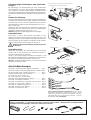 3
3
-
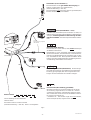 4
4
-
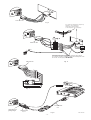 5
5
-
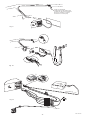 6
6
-
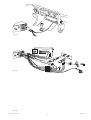 7
7
-
 8
8
-
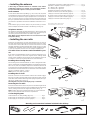 9
9
-
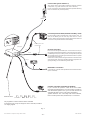 10
10
-
 11
11
-
 12
12
-
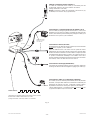 13
13
-
 14
14
-
 15
15
-
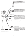 16
16
-
 17
17
-
 18
18
-
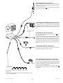 19
19
-
 20
20
-
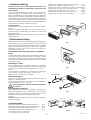 21
21
-
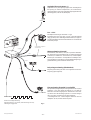 22
22
-
 23
23
-
 24
24
-
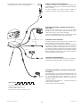 25
25
-
 26
26
-
 27
27
-
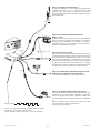 28
28


Blaupunkt HELSINKI RTM 127 Manuale del proprietario
- Tipo
- Manuale del proprietario
in altre lingue
- English: Blaupunkt HELSINKI RTM 127 Owner's manual
- français: Blaupunkt HELSINKI RTM 127 Le manuel du propriétaire
- español: Blaupunkt HELSINKI RTM 127 El manual del propietario
- Deutsch: Blaupunkt HELSINKI RTM 127 Bedienungsanleitung
- Nederlands: Blaupunkt HELSINKI RTM 127 de handleiding
- português: Blaupunkt HELSINKI RTM 127 Manual do proprietário
- svenska: Blaupunkt HELSINKI RTM 127 Bruksanvisning
Documenti correlati
-
Blaupunkt ST. LOUIS DJ Manuale del proprietario
-
Blaupunkt ST. LOUIS DJ AG Manuale del proprietario
-
-
-
-
-
-
-
-