Pioneer PDP-S37 Manuale utente
- Categoria
- Altoparlanti
- Tipo
- Manuale utente
Questo manuale è adatto anche per


English
2
Thank you for buying this Pioneer product.
Please read through these operating instructions before using
your speaker system so you will know how to make the
most of its performance. After you have finished reading the
instructions, put them away in a safe place for future
reference.
WARNING:
Handling the power cord on this product or cords associated
with accessories sold with the product will expose you to
lead, a chemical known to the State of California and other
governmental entities to cause cancer and birth defects or
other reproductive harm.
Wash hands after handling.
CAUTION
This product is designed exclusively for use with the Pioneer
Plasma Display. For more information on compatibility, please
consult with your nearest Pioneer authorized dealer or service
center.
BEFORE USE
÷ The nominal impedance of this speaker system is 8 ohms.
÷ In order to prevent damage to the speaker system
resulting from input overload, please observe the
following precautions:
÷ Do not supply power to the speaker system in
excess of the maximum permissable input. This can
result in damage or a possible fire hazard.
÷ When connecting or disconnecting pin-plugs, be
sure that amplifier power is OFF.
÷ When using a graphic equalizer to emphasize loud
sounds of a high frequency range, do not use
excessive amplifier volume.
÷ Do not force a low-powered amplifier to produce a
loud volume of sound (the amplifier’s harmonic
distortion will be increased, and you may damage
the speaker).
÷ Please handle the speakers with sufficient care, as
the grille net and the cabinet can become damaged
or broken when they are subjected to strong external
impacts.
÷ Placing a CRT computer screen or CRT monitor near to
the speakers may result in interference or color distortion.
If this happens, distance the monitor from the speakers.
Installation
÷ Consult your dealer if you encounter any difficulties
with this installation.
÷ Pioneer is not liable for any damage resulting from
improper installation, improper use, modification, or
natural disasters.
CHECKING THE ACCESSORIES
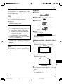
7 Speaker Cable × 2
7
Speakers Mounting Screw (M5 × 10 mm: Black) × 16
7 Speaker Mounting Bracket
For LEFT-TOP
For LEFT-BOTTOM
For RIGHT-TOP
For RIGHT-BOTTOM
7 Padding Strip × 2
(For Flush mounting)
When speakers are mounted Flush, they are affixed to
the side of the speaker as a buffer.
7 Operating Instructions × 1
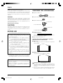
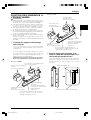
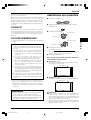
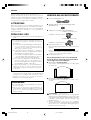
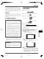
There are two ways to mount these speakers,
either Air mount or Flush mount.
7 Air mount
There is a gap of air of about 15 mm between the speakers
and the display.
Speakers
7 Flush mount
The speakers are direct against the display.
Speakers
CAUTION:
÷
Do not place force on the speakers’ front panel grille net,
or stick your finger or other object into the front of the
speaker, since you may damage the grille net or speaker
unit itself.
÷
Do not use these speakers with anything other than the
Plasma Display. Doing so may result in damage or fire.
SRD1294A_01-07/En 6/16/05, 5:55 PM2

3
English
English
MOUNTING THE SPEAKERS TO
YOUR PLASMA DISPLAY
Warning
÷
Attach the Plasma Display to the stand before installing
the speakers. See the Operating Instructions packed
together with the stand for how to assemble the stand.
÷
When mounting the speakers, only use the screws
enclosed. Using any screws other than those enclosed
may cause the speakers to come loose and fall.
÷
When mounting the speakers, be sure to tighten the
screws securely so they will not come loose.
÷
Do not lift up the display by the speakers. A speaker may
come off, so carry the display by holding it by the bottom
and its handle.
÷
If you wish to change from Flush mounting to Air mounting
or vice versa:
Remove the speaker mounting brackets from the
speakers and the display and remount them from the
beginning.
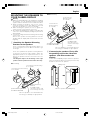
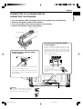
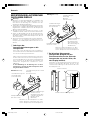
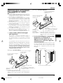
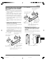
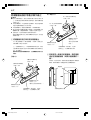
1 Attaching the Speaker Mounting
Brackets to the Speakers
There is a left speaker and a right speaker. When you
are mounting them, check the label on the back to get
them right.
There are top and bottom speaker mounting brackets
for both the left and the right speaker. Attach the
appropriate bracket to the top and the bottom on the
back of the speakers with the enclosed screws. (See
Diagram)
The diagram depicts the mounting of the right
speaker. The left speaker mounts in the same way.
Air mounting
Place the speaker so its terminals (bottom)
are facing you. (Example of right speaker)
Flush mounting
Place the speaker so its terminals (bottom)
are facing you. (Example of right speaker)
2 If mounting the speakers Flush, affix
the padding strip to the side of the
speakers (side that touches the
display).
Use the enclosed padding strips to buffer the speakers
when mounting them Flush. Peel off the protective strip
and affix to the side of the speakers.
(10)
Where to position the padding strip
Speaker Mounting Brackets
(For RIGHT- BOTTOM)
Screw Holes for Air mounting
(2 on outside)
Screw Holes for Air mounting
(2 on outside)
Speaker Mounting
Brackets
(For RIGHT-TOP)
(The skinny slot is used
for mounting to the top.)
Speaker Mounting Brackets
(For RIGHT-BOTTOM)
Screw Holes for
Flush mounting
(2 on inside)
Screw Holes for
Flush mounting
(2 on inside)
Speaker Mounting
Brackets
(For RIGHT-TOP)
(The skinny slot is
used for mounting to
the top.)
Padding Strip
SRD1294A_01-07/En 6/16/05, 5:55 PM3

English
4
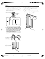
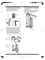
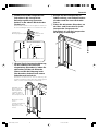
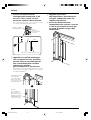
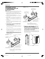
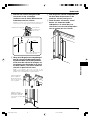
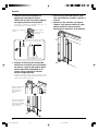
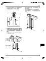
3 Screw an enclosed screw into the
speaker mounting hole (lower of the
two) at the top, back of the display.
Do not tighten it all the way yet. Leave it loose, with
about 5 mm left to tighten.
4 Hang the speaker mounting bracket
on the screw you installed at the top
by passing the wide part over it and
lowering into the slot; screw in the
lower screw temporarily.
After passing the wide part of the hole of the speaker
mounting bracket (top) over the screw, lower the speaker
onto it.
5 Adjust the position of the speaker
and then fix the upper and lower
screws firmly.
6 Tighten the two screws, at the top
and bottom for each speaker (total of
four screws), thus fixing the
speakers to the display.
Speaker Mounting Hole
Top, Back of
Display
Leave a space of about 5 mm
Top of Display
5 mm
Tighten the bottom
speaker mounting
bracket to the display
temporarily (one place
bottom).
After passing the
wide part of the hole
over the screw,
lower the speaker.
SRD1294A_01-07/En 6/16/05, 5:55 PM4

5
English
English
SYSTEM
CABLE
WHITE
BLACK
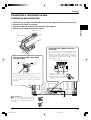
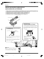
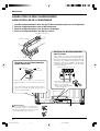
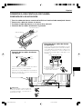
CONNECTION TO A PLASMA DISPLAY
CONNECTING THE SPEAKERS
1 Pass the speaker cables through the hole in the speaker mounting bracket.
2 Connect the speaker cables to the speaker.
3 Press the speaker cables into the groove of the bracket.
4 Connect the speaker cables to the display.
Connecting your Speaker Cables
(to the speaker)
Groove
Speaker Terminal
Speaker Cable
Connecting your Speaker Cables
(to the display)
Connect the cables correctly with respect to the
polarity of the Plasma Display and the speaker
terminals, that is, ª cable to ª terminals and ·
cable to · terminals. To do so, connect the cable
with the gray line to the ª terminals and the white
cable to the · terminals.
÷ Press the lever and insert the
end of the cable.
÷ When you release the lever,
it clamps onto the speaker
cable.
Gray Line
Push the lever, insert the end of the speaker cable
into the hole, and release the lever.
Pay attention to the polarity of the speaker terminals
when making connections. (The gray line represents
the ª terminal)
White
Gray Line White White Gray Line
2
1
3
Warning
If you insert the speaker cable too far so that
the insulation is touching the speaker
terminal, you may not get any sound.
4
(black)
(red)
SRD1294A_01-07/En 6/16/05, 5:55 PM5

English
6
CABINET MAINTENANCE
÷ Use a polishing cloth or dry cloth to wipe off dust and
dirt.
÷ When the cabinet is very dirty, wipe with a soft cloth
moistened with water-diluted cleanser; then wipe again
with a dry cloth. Do not use furniture wax or cleaners.
They may damage the surface of the cabinet.
÷ Never use thinner, benzine, insecticide sprays and other
chemicals on or near the cabinets, since these will corrode
the surfaces.
÷ When a chemical cloth is used, read the cautions for the
chemical cloth carefully.
SPECIFICATIONS
Cabinet: Bass-reflex type
Used speakers (two-way system):
Woofer (for low tones) ................ 4.8 × 13 cm cone type
Tweeter (for high tones) ........... 2.5 cm semidome type
Nominal impedance ..................................................... 8 Ω
Frequency Range ..................................... 64 to 30,000 Hz
Sensitivity (1 w, 1 m) ................................................ 81 dB
Permissible input :
Max. input .............................................................. 13 W
Rated input .............................................................. 4 W
Crossover frequency ................................................ 3 kHz
External Dimensions ...... 76.5 (W) × 717 (H) × 92 (D) mm
Weight ..................................................................... 1.7 kg
Accessory parts (for 2 speakers)
............................................................ Speaker cable × 2
...................................................... Screw (M5 × 10) × 16
............................................................................. Bracket
LEFT-TOP × 1
LEFT-BOTTOM × 1
RIGHT-TOP × 1
RIGHT-BOTTOM × 1
.............................................................. Padding strip × 2
.............................................. Operating Instructions × 1
NOTE:
Specifications and design subject to possible modification
without notice, due to improvements.
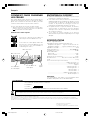
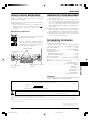
SYSTEM
CABLE
WHITE
BLACK
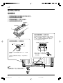
∞ Rear of Display
Speaker Cable
Speed Clamp
Mounting Hole
Speed
Clamp
Speed Clamp
Mounting Hole
Published by Pioneer Corporation.
Copyright © 2005 Pioneer Corporation.
All rights reserved.
If you want to dispose this product, do not mix it with general household waste. There is a separate collection system for used electronic products in
accordance with legislation that requires proper treatment, recovery and recycling.
Private households in the 25 member states of the EU, in Switzerland and Norway may return their used electronic products free of charge to designated collection
facilities or to a retailer (if you purchase a similar new one).
For countries not mentioned above, please contact your local authorities for the correct method of disposal.
By doing so you will ensure that your disposed product undergoes the necessary treatment, recovery and recycling and thus prevent potential negative effects on the
environment and human health.
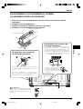
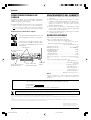
HOW TO ROURE CABLES
Speed clamps are included with the Plasma Display for tidying
your cables and keeping extra cable length out of the way.
Attach speed clamps at the direction of the running cables.
* When the Pioneer stand, sold separately, is not used, use the
two holes that are marked with arrows in the diagram (
) as
the holes for attaching speed clamps.
Using Speed Clamps
Wrap the speed clamp around the bundled
cables and press B into hole A.
To remove a speed clamp, use pliers to twist
it 90° and then pull it out. (This may result in
weakening or damaging the clamp.)
IMPORTANT NOTICE – RECORD THE MODEL NUMBER AND SERIAL NUMBERS OF THIS EQUIPMENT BELOW.
THE NUMBERS ARE ON THE REAR.
MODEL NO.
SERIAL NO.
KEEP THESE NUMBERS FOR FUTURE USE.
D1-4-2-6-2_En
SRD1294A_01-07/En 6/16/05, 5:55 PM6

7
English
English
SRD1294A_01-07/En 6/16/05, 5:55 PM7

Français
8
Merci pour votre achat de cet appareil Pioneer.
Veuillez lire attentivement toutes le mode d’emploi avant
d’utiliser vos enceintes acoustiques de façon à pouvoir en tirer
le meilleur profit. Après lecture complète du livret d’instructions
de fonctionnement, le ranger dans un endroit sûr afin de pouvoir
vous y reporter facilement en cas de besoin lors de l’utilisation
des l’enceintes acoustiques.
ATTENTION
Ce produit est conçu exclusivement pour l’utilisation avec
un écran plasma Pioneer. Pour de plus amples informations
sur la compatibilité, veuillez vous adresser au distributeur ou
au centre de service Pioneer agréé le plus proche.
AVANT USAGE
÷ L’impédance nominale de ces enceintes acoustiques est
de 8 Ω.
÷ Afin d’éviter d’endommager les enceintes
acoustiques, suite à une surcharge à l’entrée, veuillez
observer les précautions suivantes:
÷ Ne pas fournir aux enceintes une alimentation
supérieure à la valeur maximale admise, sinon
l’appareil risque d’être endommagé ou un incendie
pourrait éclater.
÷ En connectant ou en déconnectant les fiches à
plots, s’assurer que l’alimentation de l’amplificateur
est coupée.
÷ En utilisant un égalisateur graphique pour accentuer
les sons forts dans la plage des hautes fréquences,
ne pas régler l’amplificateur à un volume excessif.
÷ Ne pas contraindre un amplificateur de faible
puissance à fonctionner à un volume sonore poussé
(la distorsion harmonique de l’amplificateur sera
accrue, ce qui risquerait d’endommager les
enceintes).
÷ Manipuler les enceintes avec suffisamment de soin,
car autrement, l’enjoliveur frontal et le coffret
risqueraient d’être endommagés ou hors d’usage en
les soumettant à des chocs externes exagérés.
÷ Si un écran d’ordinateur à écran cathodique (CRT) ou un
moniteur à écran cathodique (CRT) est placé à proximité
des enceintes, il risque de présenter des interférences
ou une dénaturation des couleurs. Dans ce cas, éloignez
le moniteur des enceintes.
Installation
÷ En cas de difficultés, veuillez consulter votre revendeur.
÷ Pioneer ne saurait être tenu responsable d’aucun
dommage résultant d’une installation ou d’une
utilisation incorrecte de ce produit, de sa modification
ou encore de catastrophes naturelles.
VÉRIFICATION DES ACCESSOIRES
7 Câbles d’enceinte × 2
7
Vis pour montage des enceintes (M5 ×
10mm :
Noires
) × 16
7 Supports pour montage des enceintes
Pour côté supérieur gauche
Pour côté inférieur gauche
Pour côté supérieur droit
Pour côté inférieur droit
7 Rubans de rembourrage × 2
(Pour montage à ras)
Quand les enceintes sont montées à ras, chacun des ces
rubans doit être collé sur le côté d’une enceinte comme
tampon.
7 Mode d’emploi × 1
Il y a deux façons de monter ces enceintes,
montage à l’écart ou montage à ras.
7 Montage à l’écart
Il y a un espace vide d’environ 15 mm entre les enceintes
et l’écran.
Enceintes
7 Montage à ras
Les enceintes sont contre l’écran.
Enceintes
ATTENTION:
÷
N’appuyez pas sur la grille souple du panneau avant de
l’enceinte et n’enfoncez pas le doigt ou un objet dans
l’avant de l’enceinte, car ceci pourrait endommager la grille
souple, voire le haut-parleur proprement dit.
÷
N’utilisez pas ces enceintes avec un produit autre qu’un
écran plasma. Cela pourrait donner lieu à un
endommagement ou à un incendie.
SRD1294A_08-12/Fr 6/16/05, 5:56 PM8

9
Français
Français
FIXATION DES ENCEINTES À
L’ÉCRAN PLASMA
Avertissement
÷
Avant de procéder à l’installation des enceintes, fixez
l’écran plasma sur son socle. Se référer au mode d’emploi
fourni avec le socle pour la procédure d’assemblage.
÷
Lors du montage des enceintes, utilisez seulement les
vis fournies. Si vous utilisez des vis autres que celles
fournies, les enceintes peuvent se détacher et tomber.
÷
Lors du montage des enceintes, veillez à bien serrer les
vis de manière qu’elles ne se détachent pas.
÷
Ne soulevez pas l’écran en le tenant par les enceintes.
Les enceintes pourraient se détacher; toujours transporter
l’écran en le tenant par la base et sa poignée.
÷
Si vous souhaitez passer du montage à ras au montage à
l’écart ou vice versa:
Enlevez les supports de montage des enceintes et de
l’écran puis remettez-les en place à partir du début de la
procédure.
1 Fixation des supports de montage
aux enceintes
Il y a une enceinte gauche et une enceinte droite. Quand
vous les montez, vérifier l’étiquette située au dos pour
les différencier.
Il y a des supports de montage supérieur et inférieur
pour chacune des enceintes gauche et droite. Avec les
vis fournies, fixez les supports appropriés au dos de
chaque enceinte. (Voir l’illustration)
L’illustration représente le montage de l’enceinte
droite. L’enceinte gauche se monte de la même façon.
Montage à l’écart
Posez l’enceinte de manière que ses bornes
(sutuées en bas) soient face à vous.
(Exemple de l’enceinte droite)
Montage à ras
Posez l’enceinte de manière que ses
bornes (situées en bas) soient face à vous.
(Exemple de l’enceinte droite)
2 Si vous montez les enceintes à ras,
collez le ruban de rembourrage sur le
côté (côté qui touche l’écran).
Utilisez les rubans de rembourrage fournis pour protéger
les enceintes quand vous les montez à ras. Enlevez le
film de protection et collez le ruban sur le côté de
l’enceinte.
(10)
Où positionner le ruban de rembourrage
Support de montage
d’enceinte
(Pour côté inférieur droit)
Trous de vis pour montage
à l’écart
(2 trous sur l’extérieur)
Trous de vis pour montage à l’écart
(2 trous sur l’extérieur)
Support de montage
d’enceinte
(Pour côté supérieur droit)
(Le petit trou s’utilise pour la
fixation à la partie
supérieure.)
Support de montage
d’enceinte
(Pour côté inférieur droit)
Trous de vis pour
montage à ras
(2 trous sur l’intérieur)
Trous de vis pour
montage à ras
(2 trous sur l’intérieur)
Support de montage
d’enceinte
(Pour côté supérieur droit)
(Le petit trou s’utilise pour
la fixation à la partie
supérieure.)
Ruban de rembourrage
SRD1294A_08-12/Fr 6/16/05, 5:56 PM9

Français
10
3 Vissez une des vis fournies dans le
trou de fixation inférieur (il y a deux
trous) se trouvant à la partie
supérieure du dos de l’écran.
Ne serrez pas encore cette vis au maximum. Laissez un
espace d’environ 5 mm.
4 Accrochez le support de montage
d’enceinte à cette vis en faisant
passer la partie large du trou sur la
tête puis en l’abaissant; serrez alors
la vis inférieure provisoirement.
Après avoir fait passer la partie large du trou du support
de montage d’enceinte (supérieur) sur la vis, abaissez
l’enceinte.
5 Ajustez la position de l’enceinte, puis
serrez fermement les vis supérieures
et inférieures.
6 Montez deux autres vis, une en haut
et une en bas (total de quatre vis),
pour fixer l’enceinte à l’écran.
Trou de fixation
d’enceinte
Partie
supérieure du
dos de l’écran
Laissez un espace d’environ 5 mm
Haut de l’écran
5 mm
Fixez provisoirement
(un endroit, inférieur)
le support de
montage d’enceinte
inférieur à l’écran.
Après avoir fait
passer la partie large
du trou sur la vis,
abaissez l’enceinte.
SRD1294A_08-12/Fr 6/16/05, 5:56 PM10

11
Français
Français
SYSTEM
CABLE
WHITE
BLACK
CONNEXION À UN ÉCRAN PLASMA
CONNEXION DES ENCEINTES
1 Faites passer le câble d’enceinte dans le trou du support de montage d’enceinte.
2 Connectez le câble à l’enceinte.
3 Ajustez le câble d’enceinte dans la rainure du support.
4 Connectez le câble d’enceinte à l’écran.
Connexion des câbles d’enceinte
(aux enceintes)
Rainure
Borne d’enceinte
Câble d’enceinte
Connexion des câbles d’enceinte
(à l’écran)
Connectez les câbles correctement par rapport à la
polarité des bornes de l’écran plasma et des
enceintes, c’est-à-dire, câbles ª aux bornes ª et
câbles · aux bornes ·. Pour ce faire, connectez le
câble portant le trait gris aux bornes ª et le câble
blanc aux bornes ·.
÷ Appuyez sur le levier et
insérez l’extrémité du câble.
÷ Quand vous relâchez le levier,
la borne serre sur le câble
d’enceinte.
Trait gris
Appuyez sur le levier, insérez l’extrémité du câble
d’enceinte dans le trou, puis relâchez le levier.
Lors de la connexion, faites attention à la polarité
des bornes d’enceinte. (Le trait gris correspond à la
borne ª )
Blanc
Trait gris Blanc Blanc Trait gris
2
1
3
Avertissement
Si vous insérez le câble d’enceinte trop loin
au point que l’isolant touche la borne
d’enceinte, il est possible qu’aucun son ne
soit obtenu.
4
(Noir)
(Rouge)
SRD1294A_08-12/Fr 6/16/05, 5:56 PM11

Français
12
ENTRETIEN DU COFFRET
÷ Utiliser un chiffon à polir ou un chiffon sec pour essuyer
la poussière et éliminer les salissures.
÷ Si le coffret est très sale, le frotter avec un chiffon doux
imbibé de liquide à nettoyer dilué d’eau. Ensuite, essuyer
à nouveau avec un chiffon sec. Ne pas utiliser de cire à
meuble ou de produits de nettoyage corrosifs. Ils
risqueraient d’endommager la surface du coffret.
÷ Ne jamais utiliser non plus de diluant, de benzine,
d’insecticides en vaporisateur et autres produits
chimiques sur le coffret ou à proximité, car ils risquent
de corroder les surfaces.
÷ Si l’on utilise un chiffon chimique, lire et observer
attentivement les précautions à prendre pour son usage
adéquat.
SPECIFICATIONS
Coffret : Type bass-reflex
Haut-parleurs utilisés (système à double voie) :
Haut-parleur de graves ....... Type à cône de 4,8 × 13 cm
Haut-parleur d’aigus ......... Type à semi-dôme de 2,5 cm
Impédance nominale ................................................... 8 Ω
Plage de fréquences ................................. 64 à 30.000 Hz
Sensibilité (1 w, 1 m) ............................................... 81 dB
Entrée admissible :
Entrée max. ............................................................ 13 W
Entrée nominale ...................................................... 4 W
Fréquence de recouvrement ................................... 3 kHz
Encombrement ................. 76,5 (L) × 717 (H) × 92 (P) mm
Poids ........................................................................ 1,7 kg
Pièces accessoires (pour 2 enceintes)
...................................................... Câbles d’enceinte × 2
............................................................ Vis (M5 x 10) × 16
............................................................................ Support
Supérieur gauche × 1
Inférieur gauche × 1
Supérieur droit × 1
Inférieur droit × 1
.............................................. Ruban de rembourrage × 2
.......................................................... Mode d'emploi × 1
REMARQUE:
Les spécifications et la finition sont susceptibles d’être
modifiées sans préavis en vue de l’amélioration.
SYSTEM
CABLE
WHITE
BLACK
∞ Dos de l’écran
Câble d’enceinte
Trou de fixation
de collier rapide
Collier
rapide
Trou de fixation de
collier rapide
Publication de Pioneer Corporation.
© 2005 Pioneer Corporation.
Tous droits de reproduction et de traduction réservés.
Si vous souhaitez vous débarrasser de cet appareil, ne le mettez pas à la poubelle avec vos ordures ménagères. Il existe un système de collecte séparé
pour les appareils électroniques usagés, qui doivent être récupérés, traités et recyclés conformément à la législation.
Les habitants des 25 états membres de l’UE, de Suisse et de Norvège peuvent retourner gratuitement leurs appareils électroniques usagés aux centres de collecte
agréés ou à un détaillant (si vous rachetez un appareil similaire neuf).
Dans les pays qui ne sont pas mentionnés ci-dessus, veuillez contacter les autorités locales pour savoir comment vous pouvez vous débarrasser de vos appareils.
Vous garantirez ainsi que les appareils dont vous vous débarrassez sont correctement récupérés, traités et recyclés et préviendrez de cette façon les impacts néfastes
possibles sur l’environnement et la santé humaine.
COMMENT FAIRE CHEMINER
LES CÂBLES
Des colliers rapides et des colliers à oeil sont fournis avec le
système pour permettre la mise en faisceau des câbles.
Après avoir constitué les faisceaux de câbles, procédez
comme il est dit ci-dessous pour les faire cheminer.
Fixez les colliers rapides sur le passage des câbles installés.
* Quand le support Pioneer, vendu séparément, n’est pas utilisé,
utilisez les deux trous indiqués par des flèches sur l’illustration
(
) pour la fixation des colliers rapides.
Utilisation de colliers rapides
Enroulez le collier autour des câbles en
faisceau puis enfoncez B dans le trou A.
Pour enlever un collier rapide, utilisez des
pinces pour le tourner de 90° puis le tirer
vers l’extérieur. (Ceci peut affaiblir ou
endommager le collier.)
– VEUILLEZ REPORTER CI-DESSOUS LES NUMEROS DE MODELE ET DE SERIE DE L’EQUIPEMENT.
CES NUMEROS APPARAISSENT A L’ARRIERE.
Nº MODELE :
Nº SERIE :
VEUILLEZ CONSERVER CES NUMEROS EN VUE DE FUTURES UTILISATIONS.
AVIS IMPORTANT
SRD1294A_08-12/Fr 6/16/05, 5:56 PM12

13
Deutsch
Deutsch
Wir danken Ihnen dafür, dass Sie sich für ein Produkt von
Pioneer entschieden haben.
Bitte lesen Sie vor der Verwendung Ihrer Lautsprecheranlage
diese Anleitung aufmerksam durch, um die Vorzüge des
Systems optimal ausnützen zu können. Nachdem Sie die
Bedienungsanleitung durchgelesen haben, bewahren Sie sie
sorgfältig auf, um sich im Bedarfsfall jederzeit darauf beziehen
zu können.
VORSICHT
Dieses Produkt ist für ausschließlichen Gebrauch mit dem
Pioneer Plasma Display vorgesehen. Weitere Informationen
zur Kompatibilität bringen Sie bitte bei Ihrem autorisierten
Pioneer-Händler oder einer Pioneer-Kundendienststelle in
Erfahrung.
VOR DER VERWENDUNG
÷ Die Nennimpedanz dieses Lautsprechersystems beträgt
8 Ohm.
÷ Um eine Beschädigung des Lautsprechersystems
durch ein zu starkes Eingangssignal zu vermeiden,
müssen die folgenden Hinweise unbedingt beachtet
werden:
÷ Keinesfalls die max. zulässige Belastbarkeit
(Eingangspegel) der Lautsprecher überschreiten.
Anderenfalls können Schäden oder Brandgefahr
resultieren.
÷ Vor dem Anschließen und Abziehen von
Stiftsteckern muss die Stromversorgung zum
Verstärker unbedingt auf OFF gestellt werden.
÷ Wenn ein Graphik-Equalizer verwendet wird, um
die Töne im Hochfrequenzbereich zu verstärken,
darf die Lautstärke des Verstärkers nicht zu hoch
eingestellt werden.
÷ Versuchen Sie nicht, hohe Lautstärken über einen
Lautsprecher mit nicht ausreichender Kapazität
wiederzugeben (dies führt zu einer Verstärkung des
Klirrfaktors; außerdem kann eine Beschädigung der
Lautsprecher die Folge sein).
÷ Die Lautsprecher sind vorsichtig zu behandeln, da
Ziergitter und Gehäuse durch starke Stöße und
Erschütterungen verkratzt bzw. beschädigt werden
können.
÷ Bei unzureichender Entfernung von CRT-Computer-
Monitoren oder CRT-Monitoren können die Lautsprecher
Bildrauschen oder Farbstörungen verursachen. In diesem
Fall die Entfernung zwischen Lautsprecher und Display
vergrößern.
Installation
÷ Wenn es bei dieser Installation zu Problemen kommen
sollte, wenden Sie sich bitte an Ihren Händler.
÷ Pioneer haftet für keinerlei Schäden, die sich auf falsche
Installation, unsachgemäßen Gebrauch, Modifikationen
oder Naturkatastrophen zurückführen lassen.
ÜBERPRÜFEN DES ZUBEHÖRS
7 Lautsprecherkabel × 2
7
Lautsprecher-Befestigungsschraube (M5 x 10 mm:
Schwartz) × 16
7 Lautsprecherhalterung
Für oben links
Für unten links
Für oben rechts
Für unten rechts
7 Zwischenstreifen × 2
(Für bündige Montage)
Bei bündiger Montage werden die Streifen zur Polsterung
an der Seite der Lautsprecher angebracht.
7 Bedienungsanleitung × 1
Diese Lautsprecher können entweder distanziert
oder bündig montiert werden.
7 Versetzt Montage
Zwischen den Lautsprechern und dem Display entsteht
ein Luftspalt von etwa 15 mm.
7 Bündige Montage
Die Lautsprecher werden direkt an das Display angesetzt.
VORSICHT:
÷
Üben Sie keinen Druck auf die Frontverkleidung der
Lautsprecher aus, und stecken Sie weder Finger noch
andere spitze Gegenstände in die Frontverkleidung, da
dies eine Beschädigung der Frontverkleidung oder des
Lautsprechers selbst verursachen kann.
÷
Diese Lautsprecher dürfen nur mit dem Plasma Display
betrieben werden. Anderenfalls kann ein Schaden oder
Brand verursacht werden.
Lautsprecher
Lautsprecher
SRD1294A_13-17/Gr 6/16/05, 5:57 PM13

Deutsch
14
BEFESTIGEN DER LAUTSPRECHER
AM PLASMA DISPLAY
Warnung
÷
Montieren Sie das Plasma-Display vor Installation der
Lautsprecher auf dem Ständer. Beziehen Sie sich
hinsichtlich der Montage des Ständers auf die
mitgelieferte Bedienungsanleitung.
÷
Verwenden Sie zur Befestigung der Lautsprecher nur die
mitgelieferten Schrauben. Bei Gebrauch anderer als der
mitgelieferten Schrauben können sich die Lautsprecher
ablösen und herunterfallen.
÷
Beim Befestigen der Lautsprecher ziehen Sie die
Schrauben sicher an, sodass sie sich nicht lockern können.
÷
Heben Sie das Display nicht an den Lautsprechern an.
Zum Tragen ist das Display stets an der Unterseite und
am Griff zu halten, nicht an den Lautsprechern, da sich
diese lösen können.
÷
Wechseln zwischen bündiger und versetzter Montage:
Nehmen Sie die Lautsprecherhalterungen von
Lautsprechern und Display ab, und montieren Sie sie von
Neuem.
1 Anbringen der
Lautsprecherhalterungen an die
Lautsprecher
Linker und rechter Lautsprecher sind voneinander zu
unterscheiden. Prüfen Sie an der Rückseite die Aufschrift,
um eine Verwechslung auszuschließen.
Obere und untere Lautsprecherhalterungen sind sowohl
für den linken als auch den rechten Lautsprecher zu
unterscheiden. Bringen Sie die entsprechende Halterung
oben und unten an der Rückseite der Lautsprecher
mithilfe der mitgelieferten Schauben an. (Siehe
Abbildung)
In der Abbildung ist die Montage des rechten
Lautsprechers gezeigt. Der linke Lautsprecher wird
auf gleiche Weise montiert.
Versetzt Montage
Platzieren Sie den Lautsprecher so, dass
dessen Klemmen (Unterseite) nach vorne
weisen. (Beispiel für rechten Lautsprecher)
Bündige Montage
Platzieren Sie den Lautsprecher so, dass
dessen Klemmen (Unterseite) nach vorne
weisen. (Beispiel für rechten Lautsprecher)
2 Bei bündiger Montage der
Lautsprecher bringen Sie den
Zwischenstreifen an der Seite der
Lautsprecher an (an der Seite, die
das Display berührt).
Verwenden Sie die mitgelieferten Zwischenstreifen zur
Polsterung bei bündiger Montage. Ziehen Sie die
Schutzfolie ab, und bringen Sie die Streifen an der Seite
der Lautsprecher an.
(10)
Zwischenstreifen-Anbringposition
Lautsprecherhalterungen
(Für unten rechts)
Schraubenöffnungen für
versetzt Montage
(2 an Außenseite)
Schraubenöffnungen für versetzt
Montage
(2 an Außenseite)
Lautsprecherhalterungen
(Für oben rechts)
(Die Halterung mit dem
schmalen Teil dient zur
Montage an der
Oberseite.)
Lautsprecherhalterungen
(Für unten rechts)
Schraubenöffnungen
für bündige Montage
(2 an Innenseite)
Schraubenöffnungen
für bündige
Montage
(2 an Innenseite)
Lautsprecherhalterungen
(Für oben rechts)
(Die Halterung mit
dem schmalen Teil
dient zur Montage an
der Oberseite.)
Zwischenstreifen
SRD1294A_13-17/Gr 6/16/05, 5:57 PM14

15
Deutsch
Deutsch
3 Drehen Sie eine der mitgelieferten
Schrauben in die Lautsprecher-
Befestigungsöffnung (untere der
beiden) an der oberen Rückseite des
Displays ein.
Ziehen Sie die Schraube noch nicht ganz fest. Lassen Sie
bis zum vollständigen Anziehen noch etwa 5 mm Spiel.
4 Hängen Sie die Lautsprecherhalterung
an der soeben an der Oberseite
eingedrehten Schraube ein, indem Sie
den breiten Teil über die Schraube
führen und Sie die Halterung in der
Nut absenken; drehen Sie die untere
Schraube provisorisch ein.
Nachdem Sie den breiten Teil der Öffnung der
Lautsprecherhalterung (oben) über die Schraube geführt
haben, senken Sie den Lautsprecher darauf ab.
5 Bringen Sie den Lautsprecher in
Arbeitsstellung, und ziehen Sie dann
die obere und die untere Schraube
fest an.
6 Ziehen Sie die beiden Schrauben, an
der Ober- und Unterseite für jeden
Lautsprecher (insgesamt vier
Schrauben) an, um die Lautsprecher
am Display zu befestigen.
Lautsprecher-
Befestigungsöffnung
Obere
Rückseite des
Displays
Lassen Sie ein Spiel von etwa 5 mm
Oberseite des Displays
5 mm
Befestigen Sie die
untere
Lautsprecherhalterung
provisorisch am
Display (eine Stelle,
untere).
Nachdem Sie den
breiten Teil der
Öffnung über die
Schraube geführt
haben, senken Sie
den Lautsprecher ab.
SRD1294A_13-17/Gr 6/16/05, 5:57 PM15

Deutsch
16
SYSTEM
CABLE
WHITE
BLACK
ANSCHLUSS AN EIN PLASMA DISPLAY
ANSCHLIEßEN DER LAUTSPRECHER
1 Führen Sie die Lautsprecherkabel durch die Öffnung in der Lautsprecher-Montagehalterung.
2 Schließen Sie Ihre Lautsprecherkabel an den Lautsprecher an.
3 Drücken Sie das Lautsprecherkabel in die Nut der Halterung.
4 Schließen Sie Ihre Lautsprecherkabel an das Display an.
Anschließen der Lautsprecherkabel
(an Lautsprecher)
Nut
Lautsprecherklemme
Lautsprecherkabel
Anschließen der
Lautsprecherkabel (an Display)
Schließen Sie die Kabel richtig bezüglich der Polarität
des Plasma Displays und der Lautsprecherklemmen
an, d.h. Pluskabel ª an positive Klemmen ª und
Minuskabel · an negative Klemmen · . Es gilt:
Kabel mit grauem Faden an Plus ª , weißes Kabel
an Minus · .
÷ Drücken Sie den Hebel und
führen Sie das Ende des
Kabels ein.
÷ Durch Loslassen des Hebels
wird das Lautsprecherkabel
festgeklemmt.
Grauer Faden
Drücken Sie den Hebel, führen Sie das Ende des
Lautsprecherkabels in die Öffnung ein, und lassen
Sie den Hebel dann los.
Achten Sie beim Anschluss auf die Polarität der
Lautsprecherklemmen. (Das Kabel mit dem grauen
Faden ist das Pluskabel ª )
Weiß
Grauer Faden Weiß Weiß Grauer Faden
2
1
3
Warnung
Wenn Sie das Lautsprecherkabel zu weit
einführen, sodass die Isolierung die
Lautsprecherklemme berührt, erhalten Sie
unter Umständen keine Klangwiedergabe.
4
· (Schwarz)
ª (Rot)
SRD1294A_13-17/Gr 6/16/05, 5:57 PM16

17
Deutsch
Deutsch
PFLEGE DES GEHÄUSES
÷ Zum Abwischen von Staub und Verschmutzung kann ein
Poliertuch oder ein trockener Lappen verwendet werden.
÷ Wenn das Gehäuse stark verschmutzt ist, kann es mit
einem weichen, mit verdünntem Haushaltsreiniger
angefeuchteten Lappen gesäubert und dann mit einem
trockenen Lappen abgewischt werden. Keine
Möbelpolitur oder Reinigungsmittel verwenden, da diese
Mittel die Oberfläche des Gehäuses beschädigen können.
÷ Niemals Verdünner, Benzol, Insektensprays oder andere
Chemikalien am oder in der Nähe des Gehäuses
verwenden, da hierdurch die Oberfläche beschädigt wird.
÷ Vor der Verwendung eines chemischen Reinigungstuchs
unbedingt die Vorsichtshinweise sorgfältig durchlesen.
TECHNISCHE DATEN
Gehäuse: Bassreflextyp
Verwendete Lautsprecher (Zweiweg-System):
Woofer (für tiefe Frequenzen)
...................................... 4,8 × 13-cm-Konuslautsprecher
Hochtöner (für hohe Frequenzen)
............................................................... 2,5 cm Semikalotte
Nennimpedanz ............................................................. 8 Ω
Frequenzgang ........................................ 64 bis 30.000 Hz
Empfindlichkeit (1w, 1m) .........................................81 dB
Zulässige Eingangswerte:
Maximaler Eingangswert ....................................... 13 W
Nenn-Eingangswert ................................................. 4 W
Übergangsfrequenz ................................................. 3 kHz
Äußere Abmessungen ..... 76,5 (B) x 717 (H) x 92 (T) mm
Gewicht: .................................................................. 1,7 kg
Zubehörteile (für 2 Lautsprecher)
..................................................... Lautsprecherkabel × 2
................................................. Schraube (M5 x 10) × 16
......................................................................... Halterung
Oben links × 1
Unten links × 1
Oben rechts × 1
Unten rechts × 1
....................................................... Zwischenstreifen × 2
................................................. Bedienungsanleitung × 1
HINWEIS:
Die technischen Daten und das Design können aus Gründen
der Weiterentwicklung jederzeit ohne vorherige Ankündigung
geändert werden.
SYSTEM
CABLE
WHITE
BLACK
∞ Rückseite des
Displays
Befestigungsöffnung
für Schnellklemme
Schnellklemme
Befestigungsöffnung
für Schnellklemme
Lautsprecherkabel
Veröffentlicht von Pioneer Corporation.
Urheberrechtlich geschützt © 2005 Pioneer Corporation.
Alle Rechte vorbehalten.
Mischen Sie dieses Produkt, wenn Sie es entsorgen wollen, nicht mit gewöhnlichen Haushaltsabfällen. Es gibt ein getrenntes Sammelsystem für
gebrauchte elektronische Produkte, über das die richtige Behandlung, Rückgewinnung und Wiederverwertung gemäß der bestehenden Gesetzgebung
gewährleistet wird.
Privathaushalte in den 25 Mitgliedsstaaten der EU, in der Schweiz und in Norwegen können ihre gebrauchten elektronischen Produkte an vorgesehenen
Sammeleinrichtungen kostenfrei zurückgeben oder aber an einen Händler zurückgeben (wenn sie ein ähnliches neues Produkt kaufen).
Bitte wenden Sie sich in den Ländern, die oben nicht aufgeführt sind, hinsichtlich der korrekten Verfahrensweise der Entsorgung an die örtliche Kommunalverwaltung.
Auf diese Weise stellen Sie sicher, dass das zu entsorgende Produkt der notwendigen Behandlung, Rückgewinnung und Wiederverwertung unterzogen wird, und so
mögliche negative Einflüsse auf die Umwelt und die menschliche Gesundheit vermieden werden.
VERLEGUNG DER KABEL
Das Plasma-Display wird mit Schnellklemmen geliefert, um die
Kabel zu bündeln und zu verhindern, dass zu lange Kabel stören.
Bringen Sie Schnellklemmen in Kabellaufrichtung an.
* Bei Nichtgebrauch des als Sonderzubehör erhältlichen Pioneer-
Gestells verwenden Sie zum Anbringen der Schnellklemmen die
beiden in der Abbildung mit Pfeilen (
) markierten Öffnungen.
Gebrauch von Schnellklemmen
Winden Sie die Schnellklemme um das
Kabelbündel und drücken Sie B in die
Öffnung A.
Zum Abnehmen einer Schnellklemme
drehen Sie sie mit einer Zange um 90°, und
ziehen Sie sie dann ab. (Dies kann zu einer
Schwächung oder Beschädigung der
Klemme führen.)
– Notieren Sie unten die Modellnummer sowie die Seriennummer der Einheit. Sie finden
diese Nummern auf deren Rückseite.
Modellnummer:
Seriennummer:
Verwahren Sie diese Nummern für den Fall, dass Sie sie künftig brauchen.
Wichtiger Hinweis!
SRD1294A_13-17/Gr 6/16/05, 5:57 PM17

Italiano
18
Grazie per avere acquistato questo prodotto Pioneer.
Leggere attentamente queste istruzioni per l’uso prima di
utilizzare il sistema di altoparlanti per avvalersi al massimo
delle sue prestazioni. Conservare poi il manuale in un luogo
sicuro per ogni eventuale futura necessità.
ATTENZIONE
Questi accessori devono essere utilizzati esclusivamente con
gli schermi al plasma di Pioneer. Per maggiori informazioni
sulla loro compatibilità al proprio schermo si raccomanda di
rivolgersi al più vicino rivenditore o centro di riparazioni
Pioneer autorizzato.
PRIMA DELL’USO
÷ L’impedenza nominale di questo sistema di altoparlanti è
8 ohm.
÷ Per evitare danni al sistema di altoparlanti dovuti a un
sovraccarico d’ingresso, osservare le seguenti
precauzioni:
÷ Fornire al circuito degli altoparlanti un'alimentazione
che non superi il livello massimo d'ingresso
consentito. In caso contrario, sussiste il pericolo di
danni e di un eventuale incendio.
÷ Prima di procedere al collegamento o al distacco
degli spinotti, verificare che l’alimentazione elettrica
dell’amplificatore sia spenta (OFF).
÷ Se si utilizza un equalizzatore grafico per enfatizzare
i suoni alti della gamma di frequenze alte, non
aumentare troppo il volume dell’amplificatore.
÷ Non forzare un amplificatore dotato di bassi a
produrre volumi di suono alti (la distorsione
armonica dell’amplificatore potrebbe aumentare, e
gli altoparlanti potrebbero subire danni).
÷ Si prega di maneggiare con cura gli altoparlanti; la
griglia di schermo e la cassa esterna possono
danneggiarsi o rompersi se sottoposte a colpi esterni
molto forti.
÷ Sistemando il video di un computer a tubo catodico (CRT)
o un monitor a tubo catodico (CRT) vicino agli altoparlanti
è possibile che si verifichino delle interferenze o delle
alterazioni di colore. Se ciò si dovesse verificare,
distanziare il monitor dagli altoparlanti.
Installazione
÷ In caso di difficoltà con questa installazione rivolgetevi
al vostro rivenditore.
÷ Pioneer non accetta alcuna responsabilità per gli
eventuali danni causati da un’installazione non corretta,
da un uso non corretto, da modifiche apportate o da
distrastri naturali.
VERIFICA DELLE PARTI FORNITE
7 Cavo dell’altoparlante × 2
7
Viti (M5 × 10mm : Nero) per il montaggio degli
altoparlanti × 16
7 Staffa per il montaggio degli altoparlanti
Installazione a sinistra in alto
Installazione a sinistra in basso
Installazione a destra in alto
Installazione a destra in basso
7 Striscetta isolante × 2
(per il montaggio degli altoparlanti a contatto (in posizione
allineata)
Quando s’installano gli altoparlanti a contatto con lo
schermo, essi risultano fissati direttamente ai lati dello
schermo con le striscette isolanti frapposte.
7 Istruzioni per l’uso × 1
Questi altoparlanti possono essere installati in
due modi diversi: montaggio in posizione libera
e montaggio in posizione allineata.
7 Montaggio in posizione libera
Tra lo schermo e gli altoparlanti permane uno spazio d’aria
di circa 15 mm.
7 Montaggio in posizione allineata
Gli altoparlanti vanno direttamente a contatto con lo
schermo.
ATTENZIONE:
÷
Non esercitare forti pressioni sulla rete a griglia del
pannello anteriore degli altoparlanti, e non inserire le dita
o altri oggetti nel lato anteriore degli altoparlanti. Tali azioni
potrebbero causare danni alla rete a griglia o agli
altoparlanti stessi.
÷
Questi altoparlanti possono essere installati
esclusivamente sullo schermo al plasma. Installandoli in
modo diverso essi si potrebbero danneggiare oppure
potrebbero dar luogo a incendi.
Altoparlanti
Altoparlanti
SRD1294A_18-22/Ita 6/16/05, 5:58 PM18

19
Italiano
Italiano
MONTAGGIO DEGLI ALTOPARLANTI
SULLO SCHERMO AL PLASMA
Avvertimento
÷
Prima di installare gli altoparlanti provvedere a fissare lo
schermo al plasma sul proprio supporto. Per istruzioni sul
montaggio dello schermo sul supporto vedere i Istruzioni
per l’uso fornito con il supporto stesso.
÷
Per il montaggio degli altoparlanti vanno utilizzate
esclusivamente le viti fornite in dotazione. L’utilizzo di viti
diverse da quelle fornite in dotazione potrebbe infatti
determinare l’allentamento e quindi il distacco degli
altoparlanti dallo schermo.
÷
Gli altoparlanti devono essere montati serrandone bene
le viti in modo da evitare che si allentino e quindi si
distacchino dallo schermo.
÷
Lo schermo non deve mai essere sollevato afferrandolo
per gli altoparlanti. Poiché infatti questi potrebbero
distaccarsi, lo schermo deve essere afferrato per il fondo
e per le apposite maniglie.
÷
Per cambiare il tipo di montaggio da quello in posizione
libera a quello in posizione allineata o viceversa:
Rimuovere le staffe di montaggio dagli altoparlanti e dallo
schermo e quindi ripetere l’installazione dall’inizio.
1 Attacco delle staffe di montaggio
agli altoparlanti
Allo schermo si applicano l’altoparlante destro e
l’altoparlante sinistro. Durante la fase di montaggio si
raccomanda pertanto di controllarne l’etichetta
posteriore, in modo da collocarli sullo schermo in modo
corretto.
Sia l’altoparlante di destra sia quello di sinistra sono
provvisti di staffe di montaggio superiore e inferiore.
Utilizzando le viti fornite in dotazione, fissare al lato
posteriore degli altoparlanti,.sia superiormente sia
inferiormente, la staffa più appropriata. (Vedere il disegno)
Il disegno illustra il montaggio dell’altoparlante
destro. Il montaggio dell’altoparlante sinistro avviene
esattamente allo stesso modo.
Montaggio in posizione libera
Applicare l’altoparlante mantenendone i terminali (in posizione
inferiore) rivolti in avanti. (Esempio relativo all’altoparlante
destro)
Montaggio in posizione allineata
2 In caso di montaggio a contatto degli
altoparlanti si raccomanda di
applicarvi di lato (quello che va a
contatto con lo schermo) l’apposita
striscetta isolante.
Le striscette isolanti fornite in dotazione hanno lo scopo
di isolare gli altoparlanti dallo schermo quando si sceglie
il montaggio a contatto. Rimuovere la pellicola protettiva
dalle striscette ed applicarle quindi al lato degli
altoparlanti.
(10)
Dove fissare la striscetta isolante
Staffe per il montaggio degli
altoparlanti
(Per l’installazione a destra in basso)
Fori per le viti di montaggio in
posizione libera
(2 dall’esterno)
Fori per le viti di montaggio in
posizione libera
(2 dall’esterno)
Staffe per il montaggio degli
altoparlanti
(Per l’installazione a destra in alto)
(Il solco superficiale va impiegato per
l’installazione in alto.)
Staffe per il
montaggio degli
altoparlanti
(Per l’installazione a
destra in basso)
Fori per le viti di montaggio
in posizione allineata
(2 dall’interno)
Fori per le viti di montaggio
in posizione allineata
(2 dall’interno)
Staffe per il montaggio degli
altoparlanti
(Per l’installazione a destra in alto)
(Il solco superficiale va impiegato
per l’installazione in alto.)
Striscetta isolante
Applicare l’altoparlante mantenendone i
terminali (in posizione inferiore) rivolti in
avanti. (Esempio relativo all’altoparlante
destro)
SRD1294A_18-22/Ita 6/16/05, 5:58 PM19

Italiano
20
3 Inserire una vite nel foro di
montaggio dell’altoparlante (il più
basso tra i due) situato sul lato
posteriore-superiore dello schermo.
Non serrare ancora la vite. Per il momento è infatti
necessario lasciarla allentata di circa 5 mm.
4 Appendere la staffa di montaggio
alla vite appena inserita, facendovi
passare sopra la parte allargata del
foro e facendola quindi scendere
nella fessura; avvitare
provvisoriamente la vite inferiore.
Fare passare sulla vite la parte allargata del foro ricavato
nella staffa di montaggio (superiore) e farvi quindi
scendere l’altoparlante.
5 Regolare la posizione
dell’altoparlante e procedere poi a
stringere saldamente le due viti,
superiore ed inferiore.
6 Per fissare definitivamente
l’altoparlante allo schermo, serrarne
la vite in alto e quella in basso (per
un totale di quattro viti per i due
altoparlanti).
Foro di montaggio
dell’altoparlante
Lato
posteriore-
superiore dello
schermo
Lasciare uno spazio di circa 5 mm
Lato superiore dello schermo
5 mm
Avvitare
provvisoriamente
allo schermo la
parte inferiore della
staffa di montaggio
dell’altoparlante (in
un punto, inferiore).
L’altoparlante deve
essere lasciato
scendere sulla vite
dopo averne fatto
scorrere il foro sulla
testa della stessa.
SRD1294A_18-22/Ita 6/16/05, 5:58 PM20
La pagina si sta caricando...
La pagina si sta caricando...
La pagina si sta caricando...
La pagina si sta caricando...
La pagina si sta caricando...
La pagina si sta caricando...
La pagina si sta caricando...
La pagina si sta caricando...
La pagina si sta caricando...
La pagina si sta caricando...
La pagina si sta caricando...
La pagina si sta caricando...
La pagina si sta caricando...
La pagina si sta caricando...
La pagina si sta caricando...
La pagina si sta caricando...
La pagina si sta caricando...
La pagina si sta caricando...
-
 1
1
-
 2
2
-
 3
3
-
 4
4
-
 5
5
-
 6
6
-
 7
7
-
 8
8
-
 9
9
-
 10
10
-
 11
11
-
 12
12
-
 13
13
-
 14
14
-
 15
15
-
 16
16
-
 17
17
-
 18
18
-
 19
19
-
 20
20
-
 21
21
-
 22
22
-
 23
23
-
 24
24
-
 25
25
-
 26
26
-
 27
27
-
 28
28
-
 29
29
-
 30
30
-
 31
31
-
 32
32
-
 33
33
-
 34
34
-
 35
35
-
 36
36
-
 37
37
-
 38
38


Pioneer PDP-S37 Manuale utente
- Categoria
- Altoparlanti
- Tipo
- Manuale utente
- Questo manuale è adatto anche per
in altre lingue
- français: Pioneer PDP-S37 Manuel utilisateur
- español: Pioneer PDP-S37 Manual de usuario
- Deutsch: Pioneer PDP-S37 Benutzerhandbuch
- Nederlands: Pioneer PDP-S37 Handleiding
Documenti correlati
-
Pioneer PDP-S58 Istruzioni per l'uso
-
Pioneer PDP-S60 Istruzioni per l'uso
-
Pioneer PDP-S61 Istruzioni per l'uso
-
Pioneer KURO KRP-S04 Operating Instructions Manual
-
-
Pioneer PDP-S59 Istruzioni per l'uso
-
-
Pioneer PDP-S64 Istruzioni per l'uso
-
-