
O P E R A T I N G I N S T R U C T I O N
ZLD18 / ZLE18
Cylindrical photoelectric sensors


Described product
Z18 SimpleSense
ZLD18 / ZLE18
Manufacturer
SICK AG
Erwin-Sick-Str. 1
79183 Waldkirch
Germany
Legal information
This work is protected by copyright. Any rights derived from the copyright shall be
reserved for SICK AG. Reproduction of this document or parts of this document is only
permissible within the limits of the legal determination of Copyright Law. Any modifica‐
tion, abridgment or translation of this document is prohibited without the express writ‐
ten permission of SICK AG.
The trademarks stated in this document are the property of their respective owner.
© SICK AG. All rights reserved.
Original document
This document is an original document of SICK AG.
8021946 | SICK
Subject to change without notice
3

Contents
1 General safety notes......................................................................... 5
2 Notes on UL approval........................................................................ 5
3 Intended use...................................................................................... 5
4 Operating and status indicators...................................................... 5
5 Mounting............................................................................................. 5
6 Electrical installation........................................................................ 6
7 Commissioning.................................................................................. 9
8 Troubleshooting................................................................................. 10
9 Disassembly and disposal............................................................... 11
10 Maintenance...................................................................................... 11
11 Technical data.................................................................................... 12
11.1 Dimensional drawings.............................................................................. 12
CONTENTS
4
8021946 | SICK
Subject to change without notice

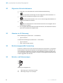
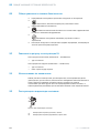
1 General safety notes
■
Read the operating instructions before commissioning.
■
Connection, mounting, and configuration may only be performed by trained
specialists.
■
2006/42/EG
NO
SAFETY
Not a safety component in accordance with the EU Machinery Directive.
■
When commissioning, protect the device from moisture and contamination.
■
These operating instructions contain information required during the life cycle of
the sensor.
2 Notes on UL approval
Blue housing types (Zxx18-1xxxxx ... Zxx18-9xxxxx):
•
Type 1 enclosure
Clear housing types (Zxx18-Axxxxx ... Zxx18-Jxxxxx):
•
Type 1 enclosure
•
Class 2 power supply required
3 Intended use
The ZLD18 / ZLE18 is an opto-electronic photoelectric retro-reflective sensor (referred
to as “sensor” in the following) for the optical, non-contact detection of objects, ani‐
mals, and persons. A reflector is required for this product to function. If the product is
used for any other purpose or modified in any way, any warranty claim against SICK AG
shall become void.
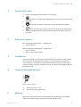
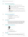
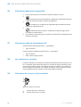
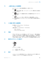
4 Operating and status indicators
1
2
Figure 1: Status indicators
1
LED indicator (green): power
2
LED indicator (orange): light received
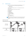
5 Mounting
Mount the sensor and the reflector using suitable mounting brackets (see the SICK
range of accessories). Align the sensor and reflector with each other.
GENERAL SAFETY NOTES 1
8021946 | SICK
Subject to change without notice
5

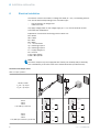
6 Electrical installation
The sensors must be connected in a voltage-free state (U
V
= 0 V). The following informa‐
tion must be observed depending on the connection type:
– Plug connection: pin assignment
– Cable: wire color
Only apply voltage/switch on the voltage supply (U
V
> 0 V) once all electrical connec‐
tions have been established.
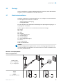
Explanation of connection terminology used in Tables 1-3:
BN = Brown
WH = White
BU = Blue
BK = Black
n. c. = no connection
Q1 = switching output 1
Q2 = switching output 2
L+ = supply voltage (Uv)
M = common
L.ON = light operate
D.ON = dark operate
NOTE
The sensor outputs may come equipped with a factory set ON delay and/or OFF delay.
This is indicated by a Txx suffix at the end of the Model Number (Zxx18-xxxxxxTxx).
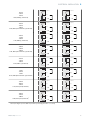
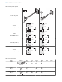
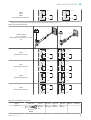
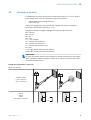
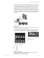
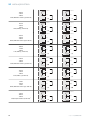
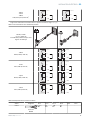
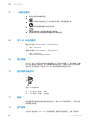
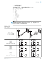
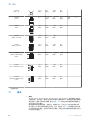
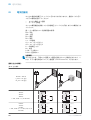
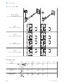
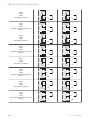
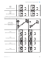
Connection and Output detail:
Table 1: Output Operation
ZLD18 / ZLE18
-x_xxxx = Q1 output
-xx_xxx = Q2 output
-xPxxxx
-x8xxxx
-xxPxxx
L.ON, PNP: Q (≤ 100 mA)
+ (L+)
Q
‒ (M)
Load
+ (L+)
Q
‒ (M)
Load
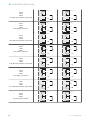
-xHxxxx
-x4xxxx
-xxHxxx
L.ON, PNP Open Collector Q (≤ 100 mA)
+ (L+)
Q
‒ (M)
Load
+ (L+)
Q
‒ (M)
Load
6 ELECTRICAL INSTALLATION
6
8021946 | SICK
Subject to change without notice

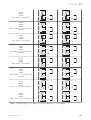
-xFxxxx
-x2xxxx
-xxFxxx
D.ON, PNP: Q (≤ 100 mA)
+ (L+)
Q
‒ (M)
Load
+ (L+)
Q
‒ (M)
Load
-xKxxxx
-x6xxxx
-xxKxxx
D.ON, PNP Open Collector Q (≤ 100 mA)
+ (L+)
Q
‒ (M)
Load
+ (L+)
Q
‒ (M)
Load
-xNxxxx
-x7xxxx
-xxNxxx
L.ON, NPN: Q (≤ 100 mA)
+ (L+)
Q
‒ (M)
Load
+ (L+)
Q
‒ (M)
Load
-xGxxxx
-x3xxxx
-xxGxxx
L.ON, NPN Open Collector Q (≤ 100 mA)
+ (L+)
Q
‒ (M)
+ (L+)
Q
‒ (M)
Load
+ (L+)
Q
‒ (M)
Load
-xExxxx
-x1xxxx
-xxExxx
D.ON, NPN: Q (≤ 100 mA)
+ (L+)
Q
‒ (M)
Load
+ (L+)
Q
‒ (M)
Load
-xJxxxx
-x5xxxx
-xxJxxx
D.ON, NPN Open Collector Q (≤ 100 mA)
+ (L+)
Q
‒ (M)
Load
+ (L+)
Q
‒ (M)
+ (L+)
Q
‒ (M)
Load
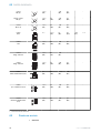
-xAxxxx
-XRxxxx
-xxAxxx
L.ON, Push-pull (≤ 100 mA)
1
+ (L+)
Q
‒ (M)
Load
+ (L+)
Q
‒ (M)
Load
-xBxxxx
-xSxxxx
-xxBxxx
D.ON, Push-pull (≤ 100 mA)
1
+ (L+)
Q
‒ (M)
Load
+ (L+)
Q
‒ (M)
Load
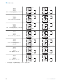
1
PNP output diagram pictured; NPN also possible by connecting the Load to + (L+) and Q
ELECTRICAL INSTALLATION 6
8021946 | SICK
Subject to change without notice
7

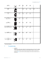
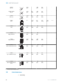
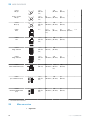
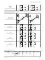
Table 2: Alarm/Health Operation
ZLD18 / ZLE18
-xx_xxx = Q2 output
Health/Alarm is always the Q2 output
-xxRxxx
Health, PNP (≤ 100 mA)
+ (L+)
Q
‒ (M)
Load
+ (L+)
Q
‒ (M)
Load
-xxTxxx
Alarm, PNP (≤ 100 mA)
+ (L+)
Q
‒ (M)
Load
+ (L+)
Q
‒ (M)
Load
-xxQxxx
Health, NPN (≤ 100 mA)
+ (L+)
Q
‒ (M)
Load
+ (L+)
Q
‒ (M)
Load
-xxSxxx
Alarm, NPN (≤ 100 mA)
+ (L+)
Q
‒ (M)
Load
+ (L+)
Q
‒ (M)
Load
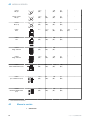
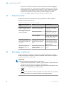
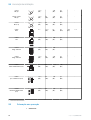
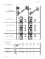
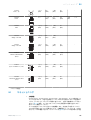
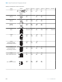
Table 3: Connection Pinout
Zxx18 Diagram Pin 1 Pin 2 Pin 3 Pin 4 Pin 5 Pin 6
-xxx1xx
0.14 mm
2
AWG26
+ (L+)
BN
Q2
WH
- (M)
BU
Q1
BK
- -
-xxx2xx
M8, 3p
3
4
1
+ (L+)
(BN)
- - (M)
(BU)
Q1
(BK)
- -
-xxx3xx / -xxx5xx
M8, 4p
3
4
2
1
+ (L+)
(BN)
Q2
(WH)
- (M)
(BU)
Q1
(BK)
- -
6 ELECTRICAL INSTALLATION
8
8021946 | SICK
Subject to change without notice

-xxx4xx
M12, 4p
3
4 1
2
+ (L+)
(BN)
Q2
(WH)
- (M)
(BU)
Q1
(BK)
- -
-xxxAxx
RJ12
2 5
n. c. + (L+)
(BN)
Q1
(BK)
Q2
(WH)
- (M)
(BU)
n. c.
-xxxBxx
RJ9
1 2
3 4
+ (L+)
(BN)
Q2
(WH)
- (M)
(BU)
Q1
(BK)
- -
-xxxCxx
Wago 733-103
3
2 1
+ (L+)
(BN)
Q1
(BK)
- (M)
(BU)
- - -
-xxxDxx
Wago 733-104
34 2 1
+ (L+)
(BN)
Q1
(BK)
- (M)
(BU)
Q2
(WH)
- -
-xxxExx
Molex 23025-0400 (2x2)
34
12
Q1
(BK)
Q2
(WH)
+ (L+)
(BN)
- (M)
(BU)
- -
-xxxFxx
Tyco 1445022-4 (1x4)
1
2
3
4
+ (L+)
(BN)
Q2
(WH)
- (M)
(BU)
Q1
(BK)
- -
-xxxGxx
Wuerth 61900411621
(1x4)
1
2
3
4
+ (L+)
(BN)
Q2
(WH)
- (M)
(BU)
Q1
(BK)
- -
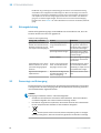
1)
Front view of connectors
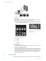
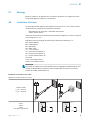
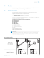
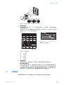
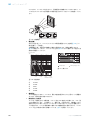
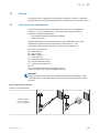
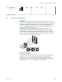
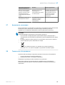
7 Commissioning
1 Alignment
ZLD18-xxxxx2, ZLD18-xxxxx8, ZLE18-xxxxx2, ZLE18-xxxxx8: align the sensor with a suitable
reflector. Select the position so that the red emitted light beam hits the center of the reflec‐
tor. The sensor must have a clear view of the reflector, with no object in the path of the
beam [see figure 2]. Ensure that the optical openings of the sensor and reflector are com‐
pletely clear.
COMMISSIONING 7
8021946 | SICK
Subject to change without notice
9

Figure 2: Alignment
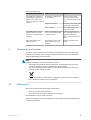
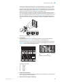
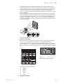
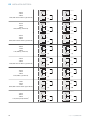
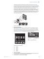
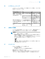
2 Sensing range
Adjust the distance between the sensor and the reflector according to the corresponding
diagram [see figure 3] (x = sensing range, y = operating reserve).
After alignment is complete, move a non-transparent object into the path of the beam. Use
table 1 to check the function. If the switching output fails to behave in accordance with
table 1, check the application conditions.
0
100
10
1
2
(6.56)
4
(13.12)
8
(26.24)
6
(19.68)
Function reserve
Distance in m (feet)
4
2
1
3
5
Sensing range
Figure 3: Characteristic curve
1
PL23FT
2
PL20A
3
P250
4
PL40A
5
PL80A
Sensing range Sensing range typ. max.
1
2
3
4
5
0
1.5
0
2.1 2.9
0
4.0 5.0
5.0
0
0
5.4 6.2
0
Distance in m (feet)
2
(6.56)
4
(13.12)
8
(26.24)
6
(19.68)
4.0
1.7
Figure 4: Bar graph
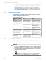
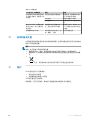
3 Sensitivity setting
Sensor not possible to be set: The sensor has been adjusted by the factory to provide maxi‐
mum sensitivity and is ready for operation.
4 Operation with marginal light reception
The sensor will provide a pre-failure notification by flashing the orange LED indicator when
operating with marginal light reception. This may be the result of incorrect alignment, cont‐
aminated optical surface(s), and/or insufficient light remission from the target. The sensor
may be equipped with a Health or Alarm output, which provide a discrete signal when the
sensor is operating in the marginal condition. Refer to table 2 for additional detail on
Health/Alarm output operation.
8 Troubleshooting
The Troubleshooting table indicates measures to be taken if the sensor stops working.
8 TROUBLESHOOTING
10
8021946 | SICK
Subject to change without notice

Table 4: Troubleshooting
LED indicator/fault pattern Cause Measures
Yellow LED does not light up
even though the light beam is
aligned to the reflector and
there is no object in the path of
the beam
No voltage or voltage below
the limit values
Check the power supply,
check all electrical connec‐
tions (cables and plug connec‐
tions)
Voltage interruptions Ensure there is a stable power
supply without interruptions
Sensor is faulty If the power supply is OK,
replace the sensor
Yellow LED flashes; if Alarm /
Health is present then take
note of the corresponding out‐
put signal
Sensor is still ready for opera‐
tion, but the operating condi‐
tions are not ideal
Check the operating condi‐
tions: Fully align the beam of
light (light spot) with the
object / Clean the optical sur‐
faces
Signal interruptions when
object is detected
Depolarizing property of the
object surface (e.g., tape),
reflection
Change the position of the
sensor
9 Disassembly and disposal
The sensor must be disposed of according to the applicable country-specific regula‐
tions. Efforts should be made during the disposal process to recycle the constituent
materials (particularly precious metals).
NOTE
Disposal of batteries, electric and electronic devices
•
According to international directives, batteries, accumulators and electrical or
electronic devices must not be disposed of in general waste.
•
The owner is obliged by law to return this devices at the end of their life to the
respective public collection points.
•
This symbol on the product, its package or in this document, indicates
that a product is subject to these regulations.
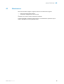
10 Maintenance
SICK recommends the following regular maintenance:
•
Clean the external optical surfaces
•
Check the screw connections and plug-in connections
No modifications may be made to devices.
Subject to change without notice. Specified product properties and technical data are
not written guarantees.
8021946 | SICK
Subject to change without notice
11

11 Technical data
ZLD18-xxxxx2 ZLD18-xxxxx8 ZLE18-xxxxx2 ZLE18-xxxxx8
Polarization
✓ ✓
- -
Sensing range (with reflector
PL80A)
6.8 m 4.2 m 7.9 m 5.0 m
Sensing range max. (with
reflector PL80A)
7.8 m 5.0 m 9.0 m 6.2 m
Light spot diameter/distance 11 mm / 500 mm 63 x 55 mm / 500
mm
11 mm / 500 mm 63 x 55 mm / 500
mm
Supply voltage V
S
DC 10 ... 30 V
1)
DC 10 ... 30 V
1)
DC 10 ... 30 V
1)
DC 10 ... 30 V
1)
Output current I
max.
≤ 100 mA ≤ 100 mA ≤ 100 mA ≤ 100 mA
Max. switching frequency 500 Hz
2)
500 Hz
2)
500 Hz
2)
500 Hz
2)
Max. response time 1 ms
3)
1 ms
3)
1 ms
3)
1 ms
3)
Enclosure rating IP67 IP67 IP67 IP67
Protection class III III III III
Circuit protection A, B, D
4)
A, B, D
4)
A, B, D
4)
A, B, D
4)
Ambient operating temperature –40 °C ... +55 °C –40 °C ... +55 °C –40 °C ... +55 °C –40 °C ... +55 °C
1)
Limit value; operation in short-circuit protection mains max. 8 A; residual ripple max. 5 V
ss
2)
With light / dark ratio 1:1
3)
Signal transit time with resistive load
4)
A = U
V
-connections reverse polarity protected
B = inputs and output reverse-polarity protected
D = outputs overcurrent and short-circuit protected
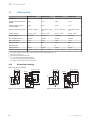
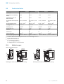
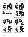
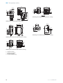
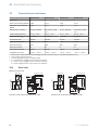
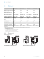
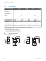
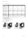
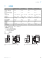
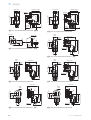
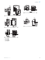
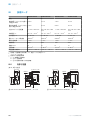
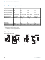
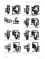
11.1 Dimensional drawings
Table 5: Dimensional drawings
13.6 (0.54)
34.8 (1.37)
M18x1
24 (0.94)
13.9
(0.55)
20.9 (0.82)
25.4 (1.0)
2 x Ø 3.5 (0.14)
4
3
2
1
14.1
(0.56)
23 (0.91)
Figure 5: ZLx18-1xxxxx / ZLx18-Axxxxx, cable
4
3
34.8 (1.37)
24 (0.94)
13.9
(0.55)
20.9 (0.82)
25.4 (1.0)
1
2
14.1
(0.56)
21.9 (0.86)
2 x Ø 3.5 (0.14)
M18x1
13.6 (0.54)
Figure 6: ZLx18-2xxxxx / ZLx18-Bxxxxx, cable
11 TECHNICAL DATA
12
8021946 | SICK
Subject to change without notice

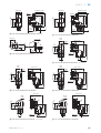
3
4
1
2
34.8 (1.37)
41.7 (1.64)
24 (0.94)
13.9
(0.55)
20.9 (0.82)
25.4 (1.0)
M18x1
2 x Ø 3.5 (0.14)
14.1
(0.56)
31.7 (1.25)
13.6 (0.54)
Figure 7: ZLx18-2xx5Ax / ZLx18-Bxx5Ax connector
4
1
2
3
13.9
(0.55)
20.9 (0.82)
34.8 (1.37)
45.1 (1.78)
24 (0.94)
25.4 (1.0)
13.6 (0.54)
2 x Ø 3.5 (0.14)
14.1
(0.56)
31.7 (1.25)
M18x1
Figure 8: ZLx18-2xx4Ax / ZLx18-Bxx4Ax
4
3
1
2
13 (0.51)
18 (0.71)
8.5
(0.33)
15.5
(0.61)
8
(0.31)
Ø 24 (0.94)
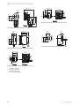
Figure 9: ZLx18-3xxxxx / ZLx18-Cxxxxx, cable
13.6
(0.54)
Ø 20.5
(0.81)
20.9 (0.82)
13.9
(0.55)
33.9 (1.33)
33.3 (1.31)
M18 x 1
12 (0.47)
42.9 (1.69)
4
1
2
3
Figure 10: ZLx18-4xxxxx / ZLx18-Dxxxxx, cable
33.9 (1.33)
40.8 (1.61)
4
3
15.1 (0.59)
9.1
(0.36)
1
2
13.6
(0.54)
Ø 20.5
(0.81)
33.3 (1.31)
12 (0.47)
Figure 11: ZLx18-4xx5Ax / ZLx18-Dxx5Ax
M18 x 1
4
3
33.9 (1.33)
44.2 (1.74)
13.6
(0.54)
Ø 20.5
(0.81)
33.3 (1.31)
12 (0.47)
15.1 (0.59)
9.1
(0.36)
1
2
Figure 12: ZLx18-4xx4Ax / ZLx18-Dxx4Ax
M18 x 1
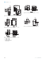
23.6 (0.93)
32.7 (1.29)
16.1 (0.63)
9.1
(0.36)
1
2
3
4
Ø 24
(0.94)
33.3 (1.31)
11.3
(0.44)
Figure 13: ZLx18-5xxxxx / ZLx18-Exxxxx, cable
M18 x 1
23.6 (0.93)
30.6 (1.2)
3
4
Ø 24
(0.94)
33.3 (1.31)
11.3
(0.44)
15.1 (0.59)
9.1
(0.36)
1
2
Figure 14: ZLx18-5xx5Ax / ZLx18-Exx5Ax
TECHNICAL DATA 11
8021946 | SICK
Subject to change without notice
13

M18 x 1
23.6 (0.93)
34 (1.34)
3
4
Ø 24
(0.94)
33.3 (1.31)
11.3
(0.44)
15.1 (0.59)
9.1
(0.36)
1
2
Figure 15: ZLx18-5xx4Ax / ZLx18-Exx4Ax
4
3
23 (0.91)
14.4 (0.57)
18 (0.71)
13.6
(0.54)
2
1
M18 x 1
3.5 (0.14)
3.5 (0.14)
Figure 16: ZLx18-6xxxxx / ZLx18-Fxxxxx, cable
4
3
1
2
22.4 (0.88)
18 (0.71)
13.6
(0.54)
31 (1.22)
12 (0.47)
19 (0.75)
25.4 (1.0)
Ø 3.5
(0.14)
Figure 17: ZLx18-7xxxxx / ZLx18-Gxxxxx, cable
4
3
1
2
Ø 24
(0.94)
18 (0.71)
26 (1.02)
11.3
(0.44)
8.5
(0.33)
15.5 (0.61)
Figure 18: ZLx18-8xxxxx / ZLx18-Hxxxxx, cable
Ø 20.5
(0.81)
4
3
23 (0.91)
18 (0.71)
12
M18 x 1
14.4 (0.57)
13.6
(0.54)
3.5 (0.14)
3.5
(0.14)
Figure 19: ZLx18-9xxxxx / ZLx18-Jxxxxx, cable
1
optical axis, sender
2
optical axis, receiver
3
LED status indicators
4
connection / strain relief
11 TECHNICAL DATA
14
8021946 | SICK
Subject to change without notice


Beschriebenes Produkt
Z18 SimpleSense
ZLD18 / ZLE18
Hersteller
SICK AG
Erwin-Sick-Str. 1
79183 Waldkirch
Deutschland
Rechtliche Hinweise
Dieses Werk ist urheberrechtlich geschützt. Die dadurch begründeten Rechte bleiben
bei der Firma SICK AG. Die Vervielfältigung des Werks oder von Teilen dieses Werks ist
nur in den Grenzen der gesetzlichen Bestimmungen des Urheberrechtsgesetzes zuläs‐
sig. Jede Änderung, Kürzung oder Übersetzung des Werks ohne ausdrückliche schriftli‐
che Zustimmung der Firma SICK AG ist untersagt.
Die in diesem Dokument genannten Marken sind Eigentum ihrer jeweiligen Inhaber.
© SICK AG. Alle Rechte vorbehalten.
Originaldokument
Dieses Dokument ist ein Originaldokument der SICK AG.
16
8021946 | SICK
Subject to change without notice

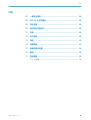
Inhalt
12 Allgemeine Sicherheitshinweise..................................................... 18
13 Hinweise zur UL Zulassung.............................................................. 18
14 Bestimmungsgemäße Verwendung............................................... 18
15 Betriebs- und Statusanzeigen.......................................................... 18
16 Montage.............................................................................................. 19
17 Elektrische Installation..................................................................... 19
18 Inbetriebnahme................................................................................. 22
19 Störungsbehebung............................................................................ 24
20 Demontage und Entsorgung............................................................ 24
21 Wartung.............................................................................................. 25
22 Technische Daten.............................................................................. 26
22.1 Maßzeichnungen...................................................................................... 26
INHALT
8021946 | SICK
Subject to change without notice
17

12 Allgemeine Sicherheitshinweise
■
Lesen Sie vor der Inbetriebnahme des Geräts die Betriebsanleitung.
■
Der Anschluss, die Montage und die Konfiguration des Geräts dürfen nur
von geschultem Fachpersonal vorgenommen werden.
■
2006/42/EG
NO
SAFETY
Bei diesem Gerät handelt es sich um kein sicherheitsgerichtetes Bauteil im
Sinne der EU-Maschinenrichtlinie.
■
Bei der Inbetriebnahme ist das Gerät ausreichend vor Feuchtigkeit und Ver‐
schmutzung zu schützen.
■
Die vorliegende Betriebsanleitung enthält Informationen, die während des Lebens‐
zyklus der Lichtschranke benötigt werden.
13 Hinweise zur UL Zulassung
Blaue Gehäusetypen (Zxx18-1xxxxx ... Zxx18-9xxxxx):
•
Type 1 enclosure
Transparente Gehäusetypen (Zxx18-Axxxxx ... Zxx18-Jxxxxx):
•
Type 1 enclosure
•
Class 2 power supply required
14 Bestimmungsgemäße Verwendung
Die ZLD18 / ZLE18 ist eine opto-elektronische Reflexions-Lichtschranke (im Folgenden
Sensor genannt) und wird zum optischen, berührungslosen Erfassen von Sachen, Tie‐
ren und Personen eingesetzt. Zur Funktion wird ein Reflektor benötigt. Bei jeder ande‐
ren Verwendung und bei Veränderungen am Produkt verfällt jeglicher Gewährleistungs‐
anspruch gegenüber der SICK AG.
15 Betriebs- und Statusanzeigen
1
2
Abbildung 20: Anzeigeelemente
1
LED-Anzeige (grün): Spannungsversorgung
2
LED-Anzeige (orange): Licht empfangen
12 ALLGEMEINE SICHERHEITSHINWEISE
18
8021946 | SICK
Subject to change without notice

16 Montage
Sensor und Reflektor an geeignete Befestigungswinkel montieren (siehe SICK-Zubehör-
Programm). Sensor und Reflektor zueinander ausrichten.
17 Elektrische Installation
Anschluss der Sensoren muss spannungsfrei (U
V
= 0 V) erfolgen. Je nach Anschlussart
sind die folgenden Informationen zu beachten:
– Steckeranschluss: Pinbelegung
– Leitung: Adernfarbe
Erst nach Anschluss aller elektrischen Verbindungen die Spannungsversorgung (U
V
> 0
V) anlegen bzw. einschalten.
Erläuterung der in Tabelle 1 bis 3 verwendeten Anschlussterminologie:
BN = braun
WH = weiß
BU = blau
BK = schwarz
n. c. = nicht angeschlossen
Q1 = Schaltausgang 1
Q2 = Schaltausgang 2
L+ = Versorgungsspannung (U
V
)
M = Masse
L.ON = hellschaltend
D.ON = dunkelschaltend
HINWEIS
Die Sensorausgänge sind möglicherweise mit einer werkseitig eingestellten EIN- und/
oder AUS-Verzögerung ausgestattet. Dies ist am Suffix Txx am Ende der Modellnummer
erkennbar (Zxx18-xxxxxxTxx).
Anschluss- und Ausgangsdetails:
Tabelle 6: Ausgangsfunktion
ZLD18 / ZLE18
-x_xxxx = Ausgang Q1
-xx_xxx = Ausgang Q2
-xPxxxx
-x8xxxx
-xxPxxx
L.ON, PNP: Q (≤ 100 mA)
+ (L+)
Q
‒ (M)
Load
+ (L+)
Q
‒ (M)
Load
MONTAGE 16
8021946 | SICK
Subject to change without notice
19

-xHxxxx
-x4xxxx
-xxHxxx
L.ON, PNP Open Collector Q (≤ 100 mA)
+ (L+)
Q
‒ (M)
Load
+ (L+)
Q
‒ (M)
Load
-xFxxxx
-x2xxxx
-xxFxxx
D.ON, PNP: Q (≤ 100 mA)
+ (L+)
Q
‒ (M)
Load
+ (L+)
Q
‒ (M)
Load
-xKxxxx
-x6xxxx
-xxKxxx
D.ON, PNP Open Collector Q (≤ 100 mA)
+ (L+)
Q
‒ (M)
Load
+ (L+)
Q
‒ (M)
Load
-xNxxxx
-x7xxxx
-xxNxxx
L.ON, NPN: Q (≤ 100 mA)
+ (L+)
Q
‒ (M)
Load
+ (L+)
Q
‒ (M)
Load
-xGxxxx
-x3xxxx
-xxGxxx
L.ON, NPN Open Collector Q (≤ 100 mA)
+ (L+)
Q
‒ (M)
+ (L+)
Q
‒ (M)
Load
+ (L+)
Q
‒ (M)
Load
-xExxxx
-x1xxxx
-xxExxx
D.ON, NPN: Q (≤ 100 mA)
+ (L+)
Q
‒ (M)
Load
+ (L+)
Q
‒ (M)
Load
-xJxxxx
-x5xxxx
-xxJxxx
D.ON, NPN Open Collector Q (≤ 100 mA)
+ (L+)
Q
‒ (M)
Load
+ (L+)
Q
‒ (M)
+ (L+)
Q
‒ (M)
Load
-xAxxxx
-XRxxxx
-xxAxxx
L.ON, Push-pull (≤ 100 mA)
1
+ (L+)
Q
‒ (M)
Load
+ (L+)
Q
‒ (M)
Load
17 ELEKTRISCHE INSTALLATION
20
8021946 | SICK
Subject to change without notice
La pagina si sta caricando...
La pagina si sta caricando...
La pagina si sta caricando...
La pagina si sta caricando...
La pagina si sta caricando...
La pagina si sta caricando...
La pagina si sta caricando...
La pagina si sta caricando...
La pagina si sta caricando...
La pagina si sta caricando...
La pagina si sta caricando...
La pagina si sta caricando...
La pagina si sta caricando...
La pagina si sta caricando...
La pagina si sta caricando...
La pagina si sta caricando...
La pagina si sta caricando...
La pagina si sta caricando...
La pagina si sta caricando...
La pagina si sta caricando...
La pagina si sta caricando...
La pagina si sta caricando...
La pagina si sta caricando...
La pagina si sta caricando...
La pagina si sta caricando...
La pagina si sta caricando...
La pagina si sta caricando...
La pagina si sta caricando...
La pagina si sta caricando...
La pagina si sta caricando...
La pagina si sta caricando...
La pagina si sta caricando...
La pagina si sta caricando...
La pagina si sta caricando...
La pagina si sta caricando...
La pagina si sta caricando...
La pagina si sta caricando...
La pagina si sta caricando...
La pagina si sta caricando...
La pagina si sta caricando...
La pagina si sta caricando...
La pagina si sta caricando...
La pagina si sta caricando...
La pagina si sta caricando...
La pagina si sta caricando...
La pagina si sta caricando...
La pagina si sta caricando...
La pagina si sta caricando...
La pagina si sta caricando...
La pagina si sta caricando...
La pagina si sta caricando...
La pagina si sta caricando...
La pagina si sta caricando...
La pagina si sta caricando...
La pagina si sta caricando...
La pagina si sta caricando...
La pagina si sta caricando...
La pagina si sta caricando...
La pagina si sta caricando...
La pagina si sta caricando...
La pagina si sta caricando...
La pagina si sta caricando...
La pagina si sta caricando...
La pagina si sta caricando...
La pagina si sta caricando...
La pagina si sta caricando...
La pagina si sta caricando...
La pagina si sta caricando...
La pagina si sta caricando...
La pagina si sta caricando...
La pagina si sta caricando...
La pagina si sta caricando...
La pagina si sta caricando...
La pagina si sta caricando...
La pagina si sta caricando...
La pagina si sta caricando...
La pagina si sta caricando...
La pagina si sta caricando...
La pagina si sta caricando...
La pagina si sta caricando...
La pagina si sta caricando...
La pagina si sta caricando...
La pagina si sta caricando...
La pagina si sta caricando...
La pagina si sta caricando...
La pagina si sta caricando...
La pagina si sta caricando...
La pagina si sta caricando...
La pagina si sta caricando...
La pagina si sta caricando...
La pagina si sta caricando...
La pagina si sta caricando...
La pagina si sta caricando...
La pagina si sta caricando...
La pagina si sta caricando...
La pagina si sta caricando...
La pagina si sta caricando...
La pagina si sta caricando...
La pagina si sta caricando...
La pagina si sta caricando...
La pagina si sta caricando...
La pagina si sta caricando...
La pagina si sta caricando...
La pagina si sta caricando...
La pagina si sta caricando...
-
 1
1
-
 2
2
-
 3
3
-
 4
4
-
 5
5
-
 6
6
-
 7
7
-
 8
8
-
 9
9
-
 10
10
-
 11
11
-
 12
12
-
 13
13
-
 14
14
-
 15
15
-
 16
16
-
 17
17
-
 18
18
-
 19
19
-
 20
20
-
 21
21
-
 22
22
-
 23
23
-
 24
24
-
 25
25
-
 26
26
-
 27
27
-
 28
28
-
 29
29
-
 30
30
-
 31
31
-
 32
32
-
 33
33
-
 34
34
-
 35
35
-
 36
36
-
 37
37
-
 38
38
-
 39
39
-
 40
40
-
 41
41
-
 42
42
-
 43
43
-
 44
44
-
 45
45
-
 46
46
-
 47
47
-
 48
48
-
 49
49
-
 50
50
-
 51
51
-
 52
52
-
 53
53
-
 54
54
-
 55
55
-
 56
56
-
 57
57
-
 58
58
-
 59
59
-
 60
60
-
 61
61
-
 62
62
-
 63
63
-
 64
64
-
 65
65
-
 66
66
-
 67
67
-
 68
68
-
 69
69
-
 70
70
-
 71
71
-
 72
72
-
 73
73
-
 74
74
-
 75
75
-
 76
76
-
 77
77
-
 78
78
-
 79
79
-
 80
80
-
 81
81
-
 82
82
-
 83
83
-
 84
84
-
 85
85
-
 86
86
-
 87
87
-
 88
88
-
 89
89
-
 90
90
-
 91
91
-
 92
92
-
 93
93
-
 94
94
-
 95
95
-
 96
96
-
 97
97
-
 98
98
-
 99
99
-
 100
100
-
 101
101
-
 102
102
-
 103
103
-
 104
104
-
 105
105
-
 106
106
-
 107
107
-
 108
108
-
 109
109
-
 110
110
-
 111
111
-
 112
112
-
 113
113
-
 114
114
-
 115
115
-
 116
116
-
 117
117
-
 118
118
-
 119
119
-
 120
120
-
 121
121
-
 122
122
-
 123
123
-
 124
124
-
 125
125


in altre lingue
Documenti correlati
-
SICK ZTE18 Istruzioni per l'uso
-
-
-
-
-
-
-
-
-