Shindaiwa ECHO MTA-TB Manuale utente
- Categoria
- Tagliaerba
- Tipo
- Manuale utente
Questo manuale è adatto anche per

1????
OPERATOR'S MANUAL
MANUEL D'UTILISATION
BEDIENUNGSANLEITUNG
MANUALE PER L'OPERATORE
MANUAL DE INSTRUCCIONES
ENGLISH
FRANÇAIS
DEUTSCH
ITALIANO
ESPAÑOL
MTA-TB
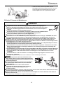
WARNING
READ THE INSTRUCTIONS CAREFULLY AND FOLLOW THE RULES FOR
SAFE OPERATION. FAILURE TO DO SO COULD RESULT IN SERIOUS
INJURY.
AVERTISSEMENT
LIRE ATTENTIVEMENT LES INSTRUCTIONS ET SUIVRE LESRÈGLES DE
SECURITÉ.LE NON-RESPECT DES RÈGLES DE SÉCURITÉ ENTRAÎNE UN
ISQUE DE BLESSURE GRAVE.
WARNUNG
LESEN SIE DIE BEDIENUNGSANLEITUNG SORGFÄLTIG DURCH, UND BE
FOLGEN SIE DIE SICHERHEITSREGELN. ANDERNFALLS BESTEHT DAS
RISIKO SCHWERER VERLETZUNGEN.
AVVERTENZA
LEGGERE E SEGUIRE ATTENTAMENTE LE ISTRUZIONI PER LAVORARE
IN CONDIZIONI DI MASSIMA SICUREZZA. LA MANCATA OSSERVANZA
DELLE ISTRUZIONI POTREBBE PROVOCARE LESIONI GRAVI.
ADVERTENCIA
LEA ATENTAMENTE LAS INSTRUCCIONES Y SIGA LAS INDICACIONES
PARA UN FUNCIONAMIENTO SEGURO. DE NO HACERLO, PODRÍA
SUFRIR LESIONES GRAVES.


1Cover
ENGLISH
(Original instructions)
OPERATOR'S MANUAL
Trimmer/Brushcutter Attachment
MTA-TB
WARNING
READ THE INSTRUCTIONS CAREFULLY AND FOLLOW THE
RULES FOR SAFE OPERATION.
FAILURE TO DO SO COULD RESULT IN SERIOUS INJURY.

2
Contents
For safe use of your product............................................................................................... 3
Description.......................................................................................................................... 7
Before you start .................................................................................................................. 8
Packing list ....................................................................................................................8
Assembly ....................................................................................................................... 8
Installation of shield ....................................................................................................... 9
Installing nylon line cutting head.................................................................................... 9
Adjusting the balance .................................................................................................. 10
Trimming operation........................................................................................................... 11
Using shoulder harness............................................................................................... 12
Basic trimming operation with nylon line cutting head ................................................. 12
Basic trimming operation with metal blade .................................................................. 14
Maintenance and care ...................................................................................................... 15
Servicing guidelines..................................................................................................... 15
Maintenance and care ................................................................................................. 15
Storage ........................................................................................................................ 18
Specifications.................................................................................................................... 19
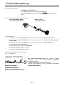
Declaration of conformity .................................................................................................. 20
UK Declaration of conformity ............................................................................................ 21

3
For safe use of your product
For safe use of yo ur product
Important information
WARNING
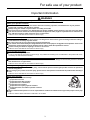
Please ensure that you read the operator's manual before using your product.
About your operator's manual
This manual contains necessary information about the assembly, operation, and maintenance of your product.
Please read it carefully and absorb its contents.
Always keep your manual in a place where it is readily accessible.
If you have lost your manual or it is damaged and no longer readable, please purchase a new one from your dealer.
The units used in this manual are SI units (International System of Units). Figures in parentheses are reference val-
ues, and there may be a slight conversion error in some cases.
Failure to do so could lead to an accident or serious injury.
Intended use of this product
This product is lightweight, high-performance unit designed for weed control, grass trimming and brush cutting in
areas difficult to control by any other means.
Do not use this unit for any purpose other than aforementioned.
The content of this manual may be changed without notice for the purpose of upgrades to the product. Some of the
illustrations used may differ from the product itself in order to make the explanations clearer.
Please consult your dealer if anything is unclear or of concern.
Failure to do so could lead to an accident or serious injury.
Do not modify the product
You must not modify the product.
To do so could lead to an accident or serious injury. Any malfunction resulting from a modification to the product will not be
covered by the manufacturer's warranty.
Do not use the product unless it has been checked and maintained
You must not use the product unless it has been checked and maintained. Always ensure that the product is checked
and maintained on a regular basis.
Failure to do so could lead to an accident or serious injury.
Loaning or assigning your product
When loaning your product to another party, ensure that the person borrowing the product receives the operator's
manual along with it.
If you assign your product to another party, please enclose the operator's manual with the product when handing it
over.
Failure to do so could lead to an accident or serious injury.
Users of the product
The product should not be used by:
people who are tired
people who have taken alcohol
people who are on medication
people who are pregnant
people who are in poor physical condition
people who have not read the operator's manual
children
Keep in mind that the operator or user is responsible for accidents or hazards occurring to other people or their prop-
erty.
Failure to observe these instructions could lead to an accident.

4
For safe use of your product
Vibration and cold
It is believed that a condition called Raynaud's Phenomenon which affects the fingers of certain individuals may be
brought about by exposure to vibration and cold. Exposure to vibration and cold may cause tingling and burning,
followed by loss of colour and numbness in the fingers. The following precautions are strongly recommended be-
cause the minimum exposure which might trigger the ailment is unknown.
Keep your body warm, especially the head and neck, feet and ankles, and hands and wrists.
Maintain good blood circulation by performing vigorous arm exercises during frequent work breaks, and also by
not smoking.
Limit the number of hours of operation. Try to fill each day with jobs where operating the trimmer or other hand-
held power equipment is not required.
If you experience discomfort redness and swelling of the fingers, followed by whitening and loss of feeling, con-
sult your physician before exposing yourself further to cold and vibration.
Failure to observe these instructions could result in damage to your health.
Repetitive stress injuries
It is believed that over-using the muscles and tendons of the fingers, hands, arms and shoulders may cause sore-
ness, swelling, numbness, weakness and extreme pain to the areas just mentioned. Certain repetitive hand activities
may put you at a high risk for developing a repetitive stress injury (RSI). To reduce the risk of RSI, do the following:
Avoid using your wrist in a bent, extended or twisted position.
Take periodic breaks to minimize repetition and rest your hands. Reduce the speed and force in which you do the
repetitive movement.
Do exercises to strengthen hand and arm muscles.
See a doctor if you feel tingling, numbness or pain in your fingers, hands, wrists or arms. The sooner RSI is diag-
nosed, the more likely permanent nerve and muscle damage can be prevented.
Failure to observe these instructions could result in damage to your health.
Proper training
Do not permit operation without proper training and protective equipment.
Be thoroughly familiar with the controls and proper use of unit.
Know how to stop the unit and shut off the engine.
Know how to unhook a harnessed unit quickly.
Never allow anyone to use the unit without proper instruction.
Failure to observe these instructions could result in damage to your health.
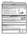
Wear proper clothing.
Secure hair so it is above shoulder length.
Do not wear ties, jewellery, or loose, dangling clothing which could be caught in the
unit.
Do not wear open toed footwear, or go bare-foot or barelegged.
Failure to observe these precautions could result in damage to your sight or hearing, or lead
to a serious injury.
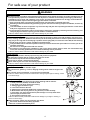
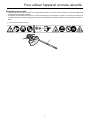
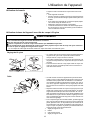
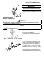
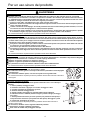
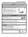
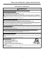
Wear protective gear
Always wear the following protective gear when working with the trimmer.
1. Head protection (helmet): Protects the head
2. Ear muffs or ear plugs: Protect the hearing
3. Safety goggles: Protect the eyes
4. Face shield: Protects the face
5. Safety gloves: Protect the hands from cold and vibration
6. Work clothes that fit (long sleeves, long trousers): Protect the body
7. Heavy duty, non-slip protective boots (with toecaps) or non-slip work shoes
(with toecaps): Protect the feet
8. Shin guards: Protect the legs
Failure to observe these precautions could result in damage to your sight or hearing, or
lead to a serious injury.
When necessary, please use the protective gear below.
Dust mask: Protects the breathing apparatus
Bee net: To deal with attacks by bees
WARNING

5
For safe use of your product
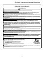
Warning notices
Other indicators
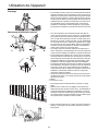
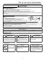
Environment of use and operation
Do not use the product:
under poor weather conditions.
on steep slopes or in places which give no secure foothold and are thus slippery.
at night or in dark places with poor visibility.
When using the product on a gentle slope, work in a level, contour-like motion.
A serious injury could result if you fall or slip, or fail to operate the product correctly.
For your own health and your safe and comfortable work, operate the machine within the air temperature range of
−5oC to 40oC.
Failure to observe these instructions could result in damage to your health.
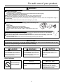
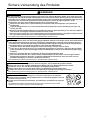
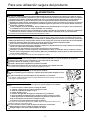
Being prepared in case of an injury
In the unlikely event of an accident or injury, please ensure that you are
prepared.
First aid kit
Towels and wipes (to stop any bleeding)
Whistle or mobile phone (for calling outside help)
If you are unable to perform first aid or call for outside help, the injury could
worsen.
Put safety first in the case of fire or smoke
If fire comes from the engine or smoke appears from any area other than the exhaust vent, first distance
yourself from the product to ensure your physical safety.
Use a shovel to throw sand or other such material on the fire to prevent it from spreading, or put it out
with a fire extinguisher.
A panicked reaction could result in the fire and other damage becoming more extensive.
WARNING
IMPORTANT
This attachment is designed for use with PAS-2620ES and M262S power source. Use of this attachment with any other
product will cause premature gear case failure and void the warranty.
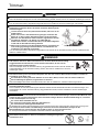
DANGER WARNING CAUTION
This symbol accompanied by the
word "DANGER" calls attentions to
an act or a condition which will lead to
serious personal injury or death of op-
erators and bystanders.
This symbol accompanied by the
word "WARNING" calls attentions to
an act or a condition which can lead to
serious personal injury or death of op-
erators and bystanders.
"CAUTION" indicates a potentially
hazardous situation which, if not
avoided, may result in minor or mod-
erate injury.
Circle and slash sym-
bol means whatever is
shown is prohibited.
NOTE IMPORTANT
This enclosed message provides tips
for use, care and maintenance of the
product.
Framed text featuring the word "IM-
PORTANT" contains important infor-
mation about the use, checking,
maintenance and storage of the prod-
uct described in this manual.

6
For safe use of your product
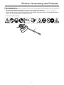
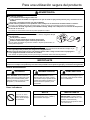
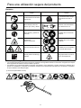
Symbols
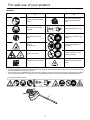
Safety decal(s)
The safety decal shown below has been attached to the products described in this manual. Ensure that you understand what
the decal means before using your product.
If the decal becomes unreadable due to wear and tear or damage, or peels off and is lost, please purchase a replacement decal
from your dealer and attach it in the location shown in the illustrations below. Ensure that the decal is readable at all times.
Symbol form/shape Symbol description/applica-
tion
Symbol form/shape Symbol description/applica-
tion
Carefully read the operator's
manual
The maximum speed of the
cutting attachment shaft in
r/min
Wear eyes, ears and head
protection Keep bystanders away 15 m
Wear foot protection and
gloves
Usage without shield not per-
mitted
Warning!
Thrown objects!
Usage of metal blades not
permitted
Warning, side thrust Usage of nylon line cutting
head not permitted
Guaranteed sound power lev-
el
Beware of high-temperature
areas
(1. Part number 890617-43130)

7
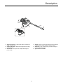
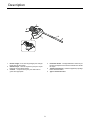
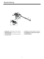
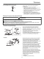
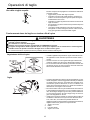
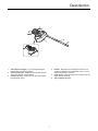
Description
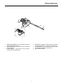
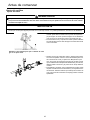
Description
1. Angle transmission - Having two gears to change the
angle of rotating axis.
2. Cutting attachment - Nylon line cutting head for cutting
grass and weed.
3. Cut off knife - Cut nylon line to adjust line length to
proper swath.
4. Shield - Device to protect the operator from accidental
contact with the cutting head and thrown objects.
5. Shaft tube - Part of the unit that provides a casing for
power transmission shaft.
6. Type and serial number

8
Before you start
Before you start
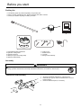
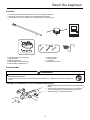
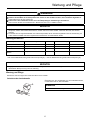
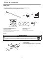
Packing list
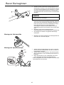
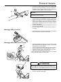
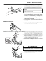
Assembly
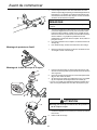
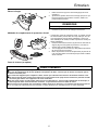
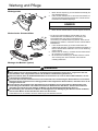
Attachment shaft assembly
1. Set power head/shaft assembly on a level surface.
2. Pull locator pin (A) out, and turn anticlockwise 1/4 turn to
lockout position.
3. Remove cardboard spacer, if necessary.
The following parts are packed separately in the packing box.
When you have unpacked the box, please check the parts that it contains.
Contact your dealer if anything is missing or broken.
1. Trimmer/Brushcutter attachment
2. Nylon line cutting head
3. Operator's manual
4. Shield (for nylon line cutting head)
5. Shield (for metal blade)
6. Locking Tool
7. Socket wrench
8. L-wrench
9. Storage hook assembly
WARNING
Read the operator's manual carefully to ensure that you assemble the product correctly.
Using a product that has been incorrectly assembled could lead to an accident or serious injury.

9
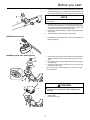
Before you start
4. Carefully fit attachment drive shaft assembly into coupler (B)
to decal assembly line (C), making sure that the inner lower
drive shaft engages into the square upper drive shaft socket.
5. Rotate locator pin (A) 1/4 turn clockwise to engage lower
shaft hole. Insure locator pin is fully engaged by twisting low-
er drive shaft. Locator pin should snap flush in coupler. Full
engagement will prevent further shaft rotation.
6. Secure lower shaft assembly to coupler by tightening clamp-
ing knob (D).
7. To disassemble, reverse assembly instructions.
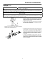
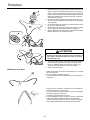
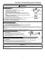
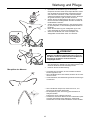
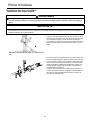
Installation of shield 1. Fit shield (A) to mounting portion of angle transmission and
tighten 4 bolts (B).
Installing nylon line cutting head 1. Insert locking tool (A) into a hole located on the right side of
angle transmission while forcing retainer spring to the left
side.
2. Insert locking tool further into blade retainer fixing slot (B) to
fix output shaft.
3. Using the socket wrench, remove the nut (C), cup (D), and
lower blade retainer (E).
Nut, cup, and lower blade retainer are not used with a nylon
line cutting head.
4. Thread nylon line cutting head (F) onto shaft (anticlockwise)
until it is tight.
5. Remove locking tool.
NOTE
Lower bearing housing and head assembly must be in line with
the motor unit.
CAUTION
Fix output shaft securely using locking tool in order to
prevent it form rotating when nylon cutting head is
mounted.

10
Before you start
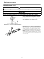
Adjusting the balance
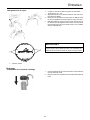
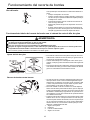
Adjusting the shoulder harness
Use a shoulder harness when provided or when recommend-
ed in this manual. Adjust both harness and the suspension
point (A) on the unit so the unit hangs with the cutting attach-
ment a few centimetres above ground level (B).
The cutting attachment and shield should be level in all direc-
tions. Harness the unit on the right side as shown.
Slide suspension point up and down the tube to find the right
balance. Rotate the clamp to level the cutting attachment and
shield. Lock in position. If the suspension point is a free-spin-
ning type, the unit may tend to roll over sideways, however,
you should still level the attachment and shield on the front-to-
rear axis.
Balancing and levelling, as above, may require relocation of
the clamp and readjustment of the harness straps. Also, each
type of cutting attachment and shield mounted on the unit may
require balancing.
WARNING
This product is designed to fit a wide variety of body sizes, but may not be adjustable for extremely tall persons. Do
not use the unit if your feet can reach the cutting attachment when the unit is attached to the harness.
IMPORTANT
A person's size can affect the balancing adjustment. Also the balancing procedure may not work with some units on some
persons. If the shoulder harness does not fit you or cannot be adjusted well, please ask your dealer for assistance.
Balance tool for a level plane of cutting head rotation

11
Trimming operation
Trimming operation
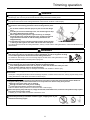
DANGER
Always stop the engine when a cutting attachment jam occurs.
Severe injury can occur if a jam is removed and the cutting attachment suddenly starts.
Do not operate the product without the shield in place.
Any objects that ricochet off the cutting attachment could cause an accident or serious injury.
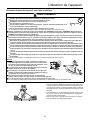
The area within a 15 m radius of the product is a danger zone. Be care-
ful to observe the following precautions while working with the prod-
uct.
Do not allow children and other people or pets to enter the danger
zone.
If another person enters the danger zone, turn off the engine to stop
the cutting attachment from rotating.
When approaching the operator, signal to him by, for example,
throwing twigs from outside the danger zone, and then check that
engine has been switched off and the cutting attachment has
stopped turning.
If more than one person is working with the product, identify the way
in which you will signal to each other and work at least 15 m apart.
Any objects that ricochet off the cutting attachment, and any contact with the cutting attachment, could cause blindness or a
fatal accident.
WARNING
Before starting work, check the area where you will be working and remove any small stones
and empty cans likely to ricochet off the cutting attachment, as well as any pieces of string
or wire that might become twisted around the cutting attachment.
An accident or serious injury can occur if foreign objects ricochet off the cutting attachment or wire
and other materials twisted round the product spring off it.
In the following situations, turn off the engine immediately and ensure that the cutting attachments have stopped
before checking each area of the product. Replace any damaged parts.
If the cutting attachment hits a rock, tree, post, or other such obstruction while you work.
If the product suddenly starts to vibrate abnormally.
Continuing to use parts when they are damaged could lead to an accident or serious injury.
Do not hold the cutting attachment up while you work. You must not work with the cutting attachments raised above
knee level.
Raising the cutting attachment above knee level brings the plane of rotation closer to the face, and any objects that fly off the
cutting attachments could cause an accident or serious injury.
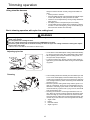
Transport of the product
When transporting in the situations described below, turn off the engine and ensure that the trimmer blade has
stopped rotating, then fit the trimmer blade cover and position the silencer away from yourself.
Moving to the place where you are working.
Moving to another area while you are working.
Leaving the place where you have been working.
Failure to observe these precautions could cause burns or serious injury.
When transporting the product by car, empty the fuel tank, fit the blade cover, and secure the product firmly in place
to prevent it from moving around.
Travelling by car with fuel in the fuel tank could lead to a fire.
Never attempt to operate the product with one hand.
Ensure that you hook your thumbs around the grips, wrapping them in your
thumb and remaining fingers.

12
Trimming operation
Using shoulder harness Always mount the trimmer correctly using the shoulder har-
ness.
Attach product to harness.
Place shoulder harness over left shoulder and adjust straps
so the quick release pin rests just below the waist.
Check for correct adjustment by moving cutting attachment
along ground.
Re-adjust position of suspension point if necessary.
The shoulder harness is fitted with an emergency release
function. In case of emergency, pull up on the collar (A) to
disconnect the machine from the strap.
Basic trimming operation with nylon line cutting head
Adjusting nylon line
Cut off knife on the shield adjusts cutting swath automatically
by cutting nylon lines evenly when attachment starts rotating.
When operating with less than maximum cutting swath, cut
two nylon lines in equal lengths.
To advance trimmer line, tap the nylon line cutting head (A)
against the ground while the head is turning at normal operat-
ing speed.
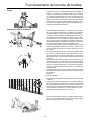
Trimming
This is feeding the trimmer carefully into the material you wish
to cut. Tilt the head slightly to direct the debris away from you.
If cutting up to a barrier such as a fence, wall or tree, approach
from an angle where any debris ricocheting off the barrier will
fly away from you.
Move the nylon line cutting head slowly until the grass is cut
right up to the barrier, but do not jam (overfeed) the line into
the barrier. If trimming up wire mesh or chain link fencing, be
careful to feed only up to the wire. If you go too far, the line will
snap off around the wire.
Trimming can be done to cut through weed stems one at a
time. Place the nylon line cutting head near the bottom of the
weed never high up, which could cause the weed to chatter
and catch the line. Rather than cut the weed right through, just
use the very end of the line to wear through the stem slowly.
1. Angle to wall
2. Debris
3. Knife side raised
4. Angle to ground
WARNING
Serious injury may result from the improper use of cutting attachment. Read and comply with all safety instructions
listed in this manual.
Do not operate with a damaged cutter.
Use only cutting attachments recommended by YAMABIKO Corporation.
Excessive nylon line beyond cut off knife could fly off when the nylon line cutting head starts rotating after adjust-
ment of nylon line length.
Failure to do so could lead to an accident or serious injury.

13
Trimming operation
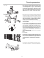
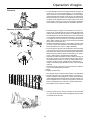
Scything
This is the cutting or mowing of large grassy areas by sweep-
ing or swinging the trimmer in a level arc. Use a smooth, easy
motion. Do not try to hack or chop down the grass. Tilt the ny-
lon line cutting head to direct the debris away from you on the
scything stroke. Then return without cutting grass for another
stroke. If you are well protected and do not care whether some
debris is thrown in your direction, you may scythe in both di-
rections.
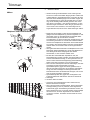
Scalping and edging
Both of these are done with the nylon line cutting head tilted at
a steep angle. Scalping (A) is removing top growth, leaving the
earth bare. Edging (B) is trimming the grass back where it has
spread over a pavement or driveway. During both edging and
scalping, hold the unit at a steep angle in a position where the
debris, and any dislodged dirt and stone, will not come back
towards you even if it ricochets off the hard surface.
Although the pictures show how to edge and scalp, every op-
erator must find for himself the angles which suit his body size
and cutting situation.
For nearly all cutting, it is good to tilt the nylon line cutting head
so that contact is made on the part of line circle where the line
is moving away from you and the shield (See appropriate pic-
ture). This results in the debris being thrown away from you.
Tilting the head to the wrong side will shoot the debris toward
you. If the nylon line cutting head is held flat to the ground so
that cutting occurs on the whole line circle, debris will be
thrown at you, drag will slow the engine, and you will use up a
lot of line.
Nylon line cutting head rotates anticlockwise. The knife will be
on the left side of the shield.
1. Debris
2. Cut on this side
Do not push the line into tough weeds, trees, or wire fences.
Pushing the line into chicken wire, chain link fencing or thick
brush can result in snapped-off line ends being hurled back at
the operator. The proper way is to cut right up to a barrier, such
as any of those mentioned, but never run the line into or
through the obstruction. Do not cut closely to obstruction or
barrier.
Avoid nylon line contact with broken wire fencing. Pieces of
wire broken off by the trimmer can be hurled at high speeds.

14
Trimming operation
Basic trimming operation with metal blade
Scything weeds
This is cutting by swinging the cutting attachment in a level
arc. It can quickly clear areas of field grass and weeds. Scyth-
ing should not be used to cut large, tough weeds or woody
growths.
If a sapling or shrub binds the cutting attachment, do not use
the cutting attachment as a lever to free the bind, because this
will cause cutting attachment failure.
Instead, shut off the engine and push the sapling or shrub to
free the blades.
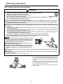
WARNING
Please observe the following instructions when trimming.
Check to ensure that the trimmer blade has been tightened securely in place.
Replace the shield if it is damaged or cracked.
Replace the trimmer blade nut when it becomes worn.
Do not cut into the ground with the blade.
Do not operate with a dull, bent, fractured or discoloured blade and worn or damaged nut.
Do not run engine at full throttle without a load.
Failure to do so could lead to an accident or serious injury.
Use only cutting attachments recommended by YAMABIKO Corporation. YAMABIKO Corporation will not be respon-
sible for the failure of cutting devices, attachments or accessories which have not been tested and approved by
YAMABIKO Corporation for use with this unit.
The type of blade used must be matched to the type and size of material cut. An improper or dull blade can cause
serious personal injury. Blades must be sharp. Dull blades increase the chance of kick-out and injury to yourself and
bystanders.
Plastic/Nylon Grass/Weed Blades may be used where ever the nylon line head is used. Do not use this blade for
heavy weeds or brush.
The 3 cutter blade is designed especially to cut weeds and grass. To avoid injury due to kickback or blade fracture,
do not use the 3 cutter blade to cut brush or trees.
8 Tooth Weed/Grass Blade is designed for grass, garden debris and thick weeds. Do not use this blade for brush
or heavy woody growth, 19 mm diameter or larger.
22 Tooth Clearing Blade is designed for dense thickets and saplings up to 64 mm diameter.
80 Tooth Brush Blade is designed for cutting brush and woody growth up to 13 mm diameter.
Damaged or shattered blades can cause accidents and serious injury.
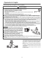
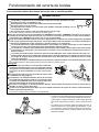
Kickback
The phenomenon that occurs if the trimmer blade comes into
contact with a tree, post, rock or other hard object while ro-
tating at high speed and reacts by recoiling powerfully and
instantaneously is known as kickback.
Causing kickback can result in a loss of control over the
product and is highly dangerous.
In particular, if the front-right quadrant of the trimmer blade
(B) strikes a shrub or other such object, the trimmer blade
will cause the product to recoil sharply backwards to the
right.
To prevent kickback, do not trim from left to right. Be careful to ensure that the trimmer blade does not strike any
hard objects.
When trimming, ensure that the object you are cutting meets the portion of the blade 1/3 in from the front edge on
the left-hand side (A).
Failure to do so could cause an injury or fatal accident.

15
Maintenance and care
Maintenance and care
Servicing guidelines
Maintenance and care
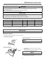
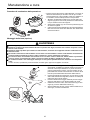
Lubricating drive shaft
Inspect the drive shaft (A) every 25 hours of use and replenish
grease if it is insufficient.
Angle transmission
1. Remove the plug (A) and drain screw (B) from the angle
transmission (C).
2. Add grease into the transmission until old grease is pushed
out. If necessary, use a low pressure pump.
3. Reinstall the drain screw and plug.
WARNING
Observe the following precautions when checking and maintaining your product after use:
Turn the engine off and do not attempt to check or maintain the product until the engine has cooled.
You could burn yourself.
Remove the spark plug cap before performing checks and maintenance.
An accident could occur if the product starts unexpectedly.
IMPORTANT
Checking and maintenance requires specialist knowledge. If you are unable to check and maintain the product or deal with a
fault yourself, consult your dealer. Do not attempt to dismantle the product.
For spare parts and consumables, please use only genuine parts and designated products and components. Using parts from
other manufacturers or non-designated components may result in a malfunction.
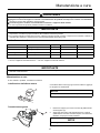
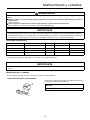
Area Maintenance Page Before use Monthly
Drive shaft Grease 15 •*
Angle transmission Grease 15 •**
Cut off knife Inspect/Clean - •
Screws, bolts and nuts Inspect, Tighten/Replace - •
* Or 25 hours, whichever occurs first. ** Or 50 hours, whichever occurs first.
IMPORTANT
Time intervals are maximum. Actual use and your experience will determine the frequency of required maintenance.
If you have any questions or problems, please contact your dealer.
NOTE
Use good quality lithium multi grease.
NOTE
Use good quality lithium multi grease.

16
Maintenance and care
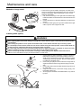
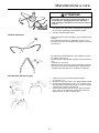
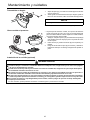
Method to change shield
There are two types of shields: namely the one used exclu-
sively for nylon line cutting head and the other one used exclu-
sively for metal blade. When metal blade is used, use the
shield for metal blade.
1. Fully loosen the bolt (A) on the right side of the bracket (B)
to slide the shield. The bolt itself cannot be removed from the
bracket.
2. Pushing the button (C), slide the shield (D) to the left and re-
move it.
3. Put shield of other type (E) into groove and slide it to the right
until it stops. Be sure to tighten the bolt.
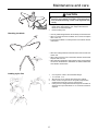
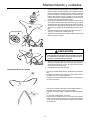
Installing blade (option)
1. Inspect blades (A) before installation. Check for sharpness.
Dull blades increase the risk of blade kickback reactions.
Small cracks can develop into fractures resulting in a piece
of blade flying off during operation. Discard cracked blades
no matter how small the crack.
2. Insert locking tool (B) into a hole located on the right side of
angle transmission while forcing retainer spring to the left
side.
3. Insert locking tool further into blade retainer fixing slot (C) to
fix output shaft.
4. Using the socket wrench, remove the nut (D), cup (E), and
lower blade retainer (F).
5. Securely tighten the blade, lower blade retainer, cup, and nut
by hand.
WARNING
Wear heavy duty gloves when working with the trimmer blade.
When replacing the trimmer blade during a trimming task, ensure that the engine is switched off and that the blades
have stopped.
When turning the product over to replace the trimmer blade, ensure that the fuel tank cap is securely in place.
Do not attempt to fit the trimmer blade with one hand or without using the socket spanner. Fit the trimmer blade ac-
curately using the supplied socket spanner and tighten firmly in position.
Do not use any tools other than the provided socket spanner to tighten the blade; a pneumatic or electric tool may
tighten the blade more than necessary and cause the nut or the output shaft to break.
If worn nut and cup for blade are used, there is a danger of blade getting loose. Replace them with new one.
Failure to do so could lead to an injury or serious accident, or cause a fire.

17
Maintenance and care
6. Tighten the nut (turn anticlockwise) using a socket wrench.
Never fasten while applying your weight. Otherwise the
thread of nut could be broken.
7. Remove locking tool.
Checking the blade
Use only blade designated for this model by the manufacturer.
When a crack is noticed on the blade, do not use it but replace
with a new one.
Ensure that the blade is correctly fitted in accordance with the
instructions.
When the cutting blade becomes dull due to wear reverse it for
further use.
When chip or bend occurs on the blade, vibration will increase.
Replace with new one.
When filing the blade file 3 cutting edges evenly using a flat file
as shown in the illustration. Otherwise, the balance will be lost
and vibration will increase.
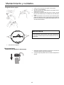
Loading nylon line
1. Cut one piece of line to recommended length.
2.4 mm dia. - 6 m
2. Align arrows on top of knob with openings in eyelets.
3. Insert one end of nylon line into an eyelet, and push line
equal distance through nylon line cutting head.
4. Hold nylon line cutting head while turning knob clockwise to
wind line onto spool until about 13 cm of each line remains
exposed.
CAUTION
Fix output shaft securely using locking tool in order to
prevent it form rotating when blade is mounted. Other-
wise, the blade fastening nut will not be tightened suffi-
ciently.

18
Maintenance and care
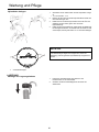
Storage
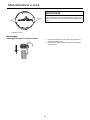
Storage hook installation
1. Insert small end of hook into locating hole on attachment
shaft.
2. Slide plastic cap onto end of attachment shaft.
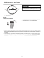
1. Wear Indicators
IMPORTANT
When the wear indicators located at the bottom of the nylon
line cutting head are worn smooth, replacement of the cover or
the entire nylon line cutting head is required.
Our goods come with guarantees that cannot be excluded under the Australian Consumer Law. You are entitled to a replace-
ment or refund for a major failure and compensation for any other reasonably foreseeable loss or damage. You are also en-
titled to have the goods repaired or replaced if the goods fail to be of acceptable quality and the failure does not amount to a
major failure.
For warranty service, find the nearest Authorised Service Dealer in our dealer locator map at www.echo australia.com.au/
en_au/finder, or by calling 1300 274 447, or by emailing or writing to salesenquires@briggsandstratton.com.au ,Briggs &
Stratton Australia Pty Ltd, Locked bag 5004, St Clair, NSW 2759.
La pagina si sta caricando...
La pagina si sta caricando...
La pagina si sta caricando...
La pagina si sta caricando...
La pagina si sta caricando...
La pagina si sta caricando...
La pagina si sta caricando...
La pagina si sta caricando...
La pagina si sta caricando...
La pagina si sta caricando...
La pagina si sta caricando...
La pagina si sta caricando...
La pagina si sta caricando...
La pagina si sta caricando...
La pagina si sta caricando...
La pagina si sta caricando...
La pagina si sta caricando...
La pagina si sta caricando...
La pagina si sta caricando...
La pagina si sta caricando...
La pagina si sta caricando...
La pagina si sta caricando...
La pagina si sta caricando...
La pagina si sta caricando...
La pagina si sta caricando...
La pagina si sta caricando...
La pagina si sta caricando...
La pagina si sta caricando...
La pagina si sta caricando...
La pagina si sta caricando...
La pagina si sta caricando...
La pagina si sta caricando...
La pagina si sta caricando...
La pagina si sta caricando...
La pagina si sta caricando...
La pagina si sta caricando...
La pagina si sta caricando...
La pagina si sta caricando...
La pagina si sta caricando...
La pagina si sta caricando...
La pagina si sta caricando...
La pagina si sta caricando...
La pagina si sta caricando...
La pagina si sta caricando...
La pagina si sta caricando...
La pagina si sta caricando...
La pagina si sta caricando...
La pagina si sta caricando...
La pagina si sta caricando...
La pagina si sta caricando...
La pagina si sta caricando...
La pagina si sta caricando...
La pagina si sta caricando...
La pagina si sta caricando...
La pagina si sta caricando...
La pagina si sta caricando...
La pagina si sta caricando...
La pagina si sta caricando...
La pagina si sta caricando...
La pagina si sta caricando...
La pagina si sta caricando...
La pagina si sta caricando...
La pagina si sta caricando...
La pagina si sta caricando...
La pagina si sta caricando...
La pagina si sta caricando...
La pagina si sta caricando...
La pagina si sta caricando...
La pagina si sta caricando...
La pagina si sta caricando...
La pagina si sta caricando...
La pagina si sta caricando...
La pagina si sta caricando...
La pagina si sta caricando...
La pagina si sta caricando...
La pagina si sta caricando...
La pagina si sta caricando...
La pagina si sta caricando...
La pagina si sta caricando...
La pagina si sta caricando...
La pagina si sta caricando...
La pagina si sta caricando...
La pagina si sta caricando...
La pagina si sta caricando...
La pagina si sta caricando...
La pagina si sta caricando...
La pagina si sta caricando...
La pagina si sta caricando...
La pagina si sta caricando...
La pagina si sta caricando...
La pagina si sta caricando...
La pagina si sta caricando...
La pagina si sta caricando...
La pagina si sta caricando...
La pagina si sta caricando...
La pagina si sta caricando...
-
 1
1
-
 2
2
-
 3
3
-
 4
4
-
 5
5
-
 6
6
-
 7
7
-
 8
8
-
 9
9
-
 10
10
-
 11
11
-
 12
12
-
 13
13
-
 14
14
-
 15
15
-
 16
16
-
 17
17
-
 18
18
-
 19
19
-
 20
20
-
 21
21
-
 22
22
-
 23
23
-
 24
24
-
 25
25
-
 26
26
-
 27
27
-
 28
28
-
 29
29
-
 30
30
-
 31
31
-
 32
32
-
 33
33
-
 34
34
-
 35
35
-
 36
36
-
 37
37
-
 38
38
-
 39
39
-
 40
40
-
 41
41
-
 42
42
-
 43
43
-
 44
44
-
 45
45
-
 46
46
-
 47
47
-
 48
48
-
 49
49
-
 50
50
-
 51
51
-
 52
52
-
 53
53
-
 54
54
-
 55
55
-
 56
56
-
 57
57
-
 58
58
-
 59
59
-
 60
60
-
 61
61
-
 62
62
-
 63
63
-
 64
64
-
 65
65
-
 66
66
-
 67
67
-
 68
68
-
 69
69
-
 70
70
-
 71
71
-
 72
72
-
 73
73
-
 74
74
-
 75
75
-
 76
76
-
 77
77
-
 78
78
-
 79
79
-
 80
80
-
 81
81
-
 82
82
-
 83
83
-
 84
84
-
 85
85
-
 86
86
-
 87
87
-
 88
88
-
 89
89
-
 90
90
-
 91
91
-
 92
92
-
 93
93
-
 94
94
-
 95
95
-
 96
96
-
 97
97
-
 98
98
-
 99
99
-
 100
100
-
 101
101
-
 102
102
-
 103
103
-
 104
104
-
 105
105
-
 106
106
-
 107
107
-
 108
108
-
 109
109
-
 110
110
-
 111
111
-
 112
112
-
 113
113
-
 114
114
-
 115
115
-
 116
116


Shindaiwa ECHO MTA-TB Manuale utente
- Categoria
- Tagliaerba
- Tipo
- Manuale utente
- Questo manuale è adatto anche per
in altre lingue
- français: Shindaiwa ECHO MTA-TB Manuel utilisateur
- español: Shindaiwa ECHO MTA-TB Manual de usuario
- Deutsch: Shindaiwa ECHO MTA-TB Benutzerhandbuch
Documenti correlati
-
Shindaiwa MTA-TB Manuale utente
-
-
-
-
-
Shindaiwa T262TXS Manuale utente
-
-
-
-