
Notice Technique
MT15000/EXT-IO
MT15000/EXT-IO-M

MT15000/EXTIO – V1.0 FRANÇAIS
p.2/7
PRASTEL France SARL
ZI Athélia II, 225 Impasse du Serpolet, 13704 LA CIOTAT Cedex
Tél : 04.42.98.06.06 – Fax : 04.42.04.53.51 –
infos@prastelfrance.fr
SOMMAIRE
Informations et recommandations .................................................................................................. 3
Caractéristiques techniques ............................................................................................................ 3
1)
MT15000/EXT-IO
2)
MT15000/EXT-IO-M
3)
COMPATIBILITE
Raccordement à la centrale MT15000/2 .......................................................................................... 4
Utilisation d’une entrée 4 états ........................................................................................................ 5
Parametrage du module sous SWAMIGO3 .................................................................................... 6
Fonctions des bornes ....................................................................................................................... 7
Cher(ère) Client(e),
Vous venez de faire l’acquisition d’un module d’extension « MT15000/EXT-IO » créée par la société française
Prastel France.
Nous vous remercions de l’intérêt que vous portez à nos produits et vous souhaitons une excellente installation
Prastel France

MT15000/EXTIO – V1.0 FRANÇAIS
p.3/7
PRASTEL France SARL
ZI Athélia II, 225 Impasse du Serpolet, 13704 LA CIOTAT Cedex
Tél : 04.42.98.06.06 – Fax : 04.42.04.53.51 –
infos@prastelfrance.fr
INFORMATIONS ET RECOMMANDATIONS
Conformément à la directive européenne UTE C00-200 décrivant les directives 89/336CEE et 92/31 CEE,
MT15000/EXT-IO est conforme aux normes :
• NF EN 50081-1 pour les émissions électromagnétiques et
• NF EN 50082-1 pour la sensibilité électromagnétique.
o Recommandations de câblage : les câbles utilisés pour le raccordement des lecteurs, réseau et autres
périphériques doivent être installés conformément aux indications décrivant le Niveau 2 (environnement protégé)
de la norme NF EN 61000-4-4.
o Ce produit doit être installé par une entreprise qualifiée. Une installation et une utilisation incorrectes peuvent
entraîner des risques de chocs électriques ou d’incendie. Avant d’effectuer l’installation, lire la notice technique et
respecter les préconisations de montage du produit.
o Pour la version 220V, après avoir éteint l’alimentation, tous les condensateurs internes se déchargeront à
un niveau sain après 60 secondes dans des conditions normales. Néanmoins, dans le cas d’une défail-
lance, les charges peuvent être maintenues beaucoup plus longtemps et des précautions adéquates
doivent être prises avant de manipuler le produit.
CARACTÉRISTIQUES TECHNIQUES
1) MT15000/EXT-IO
Consommation maximale ........................... 500 mA
Tension d’alimentation ................................ 9 – 14VDC
Poids avec le boîtier ................................... 200g
Dimensions du boîtier ................................. 157 x 120 x 30 mm
Température de fonctionnement................. - 20°C à + 50°C
Relais de commande .................................. 1A / 12V – 1A / 24V
2) MT15000/EXT-IO-M
Poids avec le boîtier ................................... 4Kg
Dimensions du boîtier ................................. 330 x 330 x 90mm
Température de fonctionnement................. - 20°C à + 50°C
Alimentation 220V intégrée :
Tension de sortie ........................................ 12V
Courant de sortie maximum ........................ 5A
Connexion pour batterie ............................. 12V, 7Ah
Relais de commande .................................. 1A / 12V – 1A / 24V
3) COMPATIBILITE
Version de la centrale MT15000/2 : V1.4 ou supérieure
Version du logiciel SWAMIGO3 : V1.0.0.7 ou supérieure
Pour mettre à jour votre centrale MT15000/2, rendez vous dans le menu « Mise à jour » de SWAMIGO3, sélec-
tionnez le fichier « UTL V1.4.bin » puis cochez les centrales à mettre à jour.
Attention :
Avant d’effectuer cette opération, assurez-vous que votre centrale soit bien connectée à votre logiciel (menu
« Configuration du site » puis « Etat des équipements »).

MT15000/EXTIO – V1.0 FRANÇAIS
p.4/7
PRASTEL France SARL
ZI Athélia II, 225 Impasse du Serpolet, 13704 LA CIOTAT Cedex
Tél : 04.42.98.06.06 – Fax : 04.42.04.53.51 –
infos@prastelfrance.fr
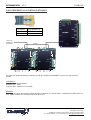
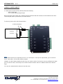
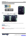
RACCORDEMENT A LA CENTRALE MT15000/2
MT15000/2 MT15000/EXT-IO
A A
B B
Vous pouvez également utiliser les borniers A et B des modules MT15000/EXT-IO pour raccorder votre bus
RS485.
Information :
2 fils (2 paires recommandées)
Distance max : 750m
Type de câble : 0,6mm (SYT conseillé)
Attention :
Ne câblez pas les fils près d’autres câbles porteurs de tensions ou courant élevés, notamment les câbles 220V ou
plus. Veillez à utiliser une même paire pour les fils A et B.
A
B
Jusqu’à 10
modules par
MT15000/2 RS485

MT15000/EXTIO – V1.0 FRANÇAIS
p.5/7
PRASTEL France SARL
ZI Athélia II, 225 Impasse du Serpolet, 13704 LA CIOTAT Cedex
Tél : 04.42.98.06.06 – Fax : 04.42.04.53.51 –
infos@prastelfrance.fr
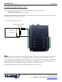
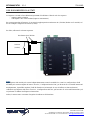
UTILISATION D’UNE ENTREE 4 ETATS
Une entrée 4 états (ou boucle équilibrée) permet de détecter les différents cas suivants :
- Entrée active ou inactive
- Fil coupé ou Fil court-circuité (entrée sabotée)
Pour utiliser ce type d’entrée, vous devez ajouter deux résistances de 4,7KOhm (fournies avec le module) sur les
fils reliant l’entrée à votre détecteur (ou autre).
Pour cela, utilisez le schéma suivant :
Note :
Chaque entrée du module peut être indépendamment utilisée en mode 2 ou 4 états. Vous pouvez configurer ces
modes depuis le menu « Technique », « Configuration du site » puis en cliquant sur les modules concernés.
De la même façon, pour ajuster les niveaux de détection (si vous utilisez une autre résistance par exemple), vous
pouvez calibrer chaque entrée depuis le menu « Technique », « Configuration du site » puis en cliquant sur les
modules concernés puis en cliquant sur le bouton « Calibrer » de l’entrée concernée.
Vous pouvez également ajuster la tolérance de détection depuis ce même menu.
Détecteur
(ou autre)
Résistances de 4,7KOhm

MT15000/EXTIO – V1.0 FRANÇAIS
p.6/7
PRASTEL France SARL
ZI Athélia II, 225 Impasse du Serpolet, 13704 LA CIOTAT Cedex
Tél : 04.42.98.06.06 – Fax : 04.42.04.53.51 –
infos@prastelfrance.fr
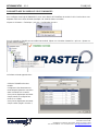
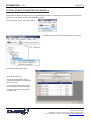
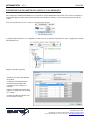
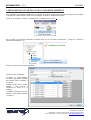
PARAMETRAGE DU MODULE SOUS SWAMIGO3
Pour configurer votre logiciel SWAMIGO3, vous aurez besoin de l’identifiant du module. Celui-ci est inscrit sur une
étiquette collée sur le haut du boitier (exemple : ID : 00001). Notez ce numéro.
Cliquer sur le bouton « Technique » puis sur « Configuration du site ».
Sous la centrale sur laquelle est raccordée votre module, cliquer sur « Modules d’extension » puis sur « ajouter un
module entrées/sorties ».
La fenêtre suivante apparait alors :
Saisissez l’identifiant de votre
module
Configurez le fonctionnement en
mode dégradé (perte de connexion
entre le module et la centrale)
Vous pouvez également renommer
chaque entrée et configurer leur
mode (2 ou 4 états)
Vous pouvez également renommer
chaque sorties (onglet « Sorties »)

MT15000/EXTIO – V1.0 FRANÇAIS
p.7/7
PRASTEL France SARL
ZI Athélia II, 225 Impasse du Serpolet, 13704 LA CIOTAT Cedex
Tél : 04.42.98.06.06 – Fax : 04.42.04.53.51 –
infos@prastelfrance.fr
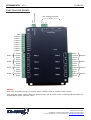
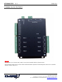
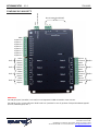
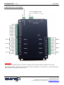
FONCTIONS DES BORNES
GND
A
B
Bus d’extension RS485
GND
Entrée 8
Entrée 7
Entrée 6
Entrée 5
Entrée 4
Entrée 3
Entrée 2
Entrée 1
GND
Alimentation 12VDC
Travail
Relais 1 Commun
Repos
Travail
Relais 2 Commun
Repos
Travail
Relais 3 Commun
Repos
Travail
Relais 4 Commun
Repos
Repos
Commun Relais 8
Travail
Repos
Commun Relais 7
Travail
Repos
Commun Relais 6
Travail
Repos
Commun Relais 5
Travail
Attention
:
Pour toutes les entrées (mode 2 ou 4 états), veillez à utiliser le GND du module comme commun.
Pour toutes les sorties, veillez à utiliser les diodes fournies avec le produit si vous commandez des dispositifs élec-
tromagnétiques (gâche, ventouse, relais, …).

Technical Instructions
MT15000/EXT-IO
MT15000/EXT-IO-M

MT15000/EXTIO – V1.0 ENGLISH
p.2/7
PRASTEL France SARL
ZI Athélia II, 225 Impasse du Serpolet, 13704 LA CIOTAT Cedex
Tél : 04.42.98.06.06 – Fax : 04.42.04.53.51 –
infos@prastelfrance.fr
CONTENTS
Information and Recommendations .................................................................................... 3
Specifications ........................................................................................................................ 3
1) MT15000/EXT-IO
2) MT15000/EXT-IO-M
3) COMPATIBILITY
Connection to MT15000/2 control unit ................................................................................ 4
Using a 4-Level input ............................................................................................................ 5
Setting Module Parameters in SWAMIGO3 ........................................................................ 6
Terminal block features ........................................................................................................ 7
Dear Customer,
You have purchased a MT15000/EXT-IO module produced by PRASTEL France.
We thank you for your interest in our products and wish you all the best with the installation procedure.
PRASTEL France

MT15000/EXTIO – V1.0 ENGLISH
p.3/7
PRASTEL France SARL
ZI Athélia II, 225 Impasse du Serpolet, 13704 LA CIOTAT Cedex
Tel.: 04.42.98.06.06 – Fax: 04.42.04.53.51 –
infos@prastelfrance.fr
INFORMATION AND RECOMMENDATIONS
In accordance with UTE C00-200 European Directive describing Directives 89/336EEC and 92/31 EEC,
MT15000/EXT-IO complies with the following standards:
• NF EN 50081-1 on electromagnetic emissions and
• NF EN 50082-1 on electromagnetic sensitivity.
o Wiring recommendations: the cables used to connect readers, network and other devices must be installed in
accordance with the instructions for Level 2, as set forth in standard NF EN 61000-4-4 (protected environment).
o This product must be installed by a qualified company. Inappropriate installation and use may entail a risk of
electric shock or fire. Please read these technical instructions before installing the product and follow assembly
instructions thereof.
o All internal capacitors in the 220V version will lose charge at a healthy level after 60 seconds once power
has been turned off, under normal conditions. However, in the event of a failure, the charge may be
maintained for much longer and adequate precautions are required before using the product.
SPECIFICATIONS
1) MT15000/EXT-IO
Maximum consumption ............................... 500 mA
Power voltage ............................................. 9 – 14V DC
Weight, with housing ................................... 200g
Housing dimensions ................................... 157 x 120 x 30 mm
Operating temperature ................................ - 20°C to + 50°C
Command relays ......................................... 1A / 12V – 1A / 24V
2) MT15000/EXT-IO-M
Weight, with housing ................................... 4Kg
Housing dimensions ................................... 330 x 330 x 90mm
Operating temperature ................................ - 20°C to + 50°C
Integrated 220V power supply:
Output voltage............................................. 12V
Maximum output current ............................. 5A
Battery connection ...................................... 12V, 7Ah
Command relays ......................................... 1A / 12V – 1A / 24V
3) COMPATIBILITY
MT15000/2 control unit version: V1.4 or higher
SWAMIGO3 software version: V1.0.0.7 or higher
To update your MT15000/2 control unit, please go to “Update” menu in SWAMIGO3, select “UTL V1.4.bin” file and
check all control units to be updated.
Warning
Before doing this, make sure that your control unit is properly connected to your software (“Site Setup” menu and
“Equipment Status”.

MT15000/EXTIO – V1.0 ENGLISH
p.4/7
PRASTEL France SARL
ZI Athélia II, 225 Impasse du Serpolet, 13704 LA CIOTAT Cedex
Tel.: 04.42.98.06.06 – Fax: 04.42.04.53.51 –
infos@prastelfrance.fr
CONNECTION TO MT15000/2 CONTROL UNIT
MT15000/2
MT15000/EXT-IO
A
A
B
B
You may also use A and B terminal blocks on MT15000/EXT-IO modules to connect your RS485 bus.
Information
2 wires (2 pairs recommended)
Max. Distance: 750m
Cable Type: 0.6mm (SYT recommended)
Warning
Do not connect the wires near other high voltage or current cables, including 220V and higher. Make sure you use
the same pair for wires A and B.
A
B
Up to 10
modules per
MT15000/2 RS485

MT15000/EXTIO – V1.0 ENGLISH
p.5/7
PRASTEL France SARL
ZI Athélia II, 225 Impasse du Serpolet, 13704 LA CIOTAT Cedex
Tel.: 04.42.98.06.06 – Fax: 04.42.04.53.51 –
infos@prastelfrance.fr
USING A 4-LEVEL INPUT
A 4-level input (or balanced loop) will help detect the following:
- Active or idle input
- Cut or shorted wire (damaged input)
Before using this type of input, two 4.7KOhm resistors (delivered with the module) must be installed on the wires
connecting the input to your detector (or another device).
To that end, please refer to the diagram below:
Note
Each module input may be separately used as 2 or 4-level input. To set up such input modes, go to “Technical”
menu, “Site Setup”, and click the relevant modules.
Likewise, in order to adjust detection levels (if you use another resistor, for instance) you may calibrate each input:
go to “Technical” menu, “Site Setup”, then click the relevant modules and the “Calibrate” button for the desired
input.
You may also adjust detection tolerance from this menu.
Detector
(or other)
4.7KOhm Resistors

MT15000/EXTIO – V1.0 ENGLISH
p.6/7
PRASTEL France SARL
ZI Athélia II, 225 Impasse du Serpolet, 13704 LA CIOTAT Cedex
Tel.: 04.42.98.06.06 – Fax: 04.42.04.53.51 –
infos@prastelfrance.fr
SETTING MODULE PARAMETERS IN SWAMIGO3
The module ID will be required to set up your SWAMIGO3 software. It is provided on a label placed on top of the
housing (e.g: ID: 00001). Please write down this number.
Click “Technical” button, then “Site Setting”.
Click “Extension modules” and then “Add a module…” below the control unit to which your module is connected.
The following window will open:
Enter your module ID
Set up fail soft operation (loss of
connection between the module and
the control unit)
You may also rename each input
and set up their mode (2 or 4-level)
You may also rename each output
(“Outputs” tab)

MT15000/EXTIO – V1.0 ENGLISH
p.7/7
PRASTEL France SARL
ZI Athélia II, 225 Impasse du Serpolet, 13704 LA CIOTAT Cedex
Tel.: 04.42.98.06.06 – Fax: 04.42.04.53.51 –
infos@prastelfrance.fr
TERMINAL BLOCK FEATURES
Warning
For all inputs (2 or 4-level mode), make sure to use the module GND as shared current.
For all outputs, make sure to use the diodes delivered with the product if electromagnetic devices are controlled
(release, sucker, relay, etc.).

Manuale tecnico
MT15000/EXT-IO
MT15000/EXT-IO-M

MT15000/EXTIO – V1.0 ITALIANO
p.2/7
PRASTEL France SARL
ZI Athélia II, 225 Impasse du Serpolet, 13704 LA CIOTAT Cedex
Tel: 04.42.98.06.06 – Fax: 04.42.04.53.51 –
infos@prastelfrance.fr
SOMMARIO
Informazioni e raccomandazioni ......................................................................................... 3
Caratteristiche tecniche ....................................................................................................... 3
1)
MT15000/EXT-IO ...........................
2)
MT15000/EXT-IO-M .......................
3)
COMPATIBILITÀ ............................
Collegamento alla centrale MT15000/2 ............................................................................... 4
Uso di un ingresso a 4 stati ................................................................................................. 5
Definizione dei parametri del modulo con SWAMIGO3 .................................................... 6
Funzione dei morsetti ........................................................................................................... 7
Gentile Cliente,
Lei ha appena acquistato un modulo di espansione “MT15000/EXT-IO” prodotto dall’azienda francese Prastel
France.
La ringraziamo per l’interesse da Lei riservato ai nostri prodotti e la preghiamo di seguire le seguenti istruzioni per
l’installazione.
Prastel France

MT15000/EXTIO – V1.0 ITALIANO
p.3/7
PRASTEL France SARL
ZI Athélia II, 225 Impasse du Serpolet, 13704 LA CIOTAT Cedex
Tel: 04.42.98.06.06 – Fax: 04.42.04.53.51 –
infos@prastelfrance.fr
INFORMAZIONI E RACCOMANDAZIONI
In conformità con la direttiva europea UTE C00-200 che include le direttive 89/336 CEE e 92/31 CEE,
MT15000/EXT-IO è conforme alle norme:
• NF EN 50081-1 in relazione alle emissioni elettromagnetiche e
• NF EN 50082-1 in relazione all’immunità elettromagnetica.
o Raccomandazioni per il cablaggio: i cavi impiegati per il collegamento dei lettori, della rete e di altre periferiche
devono essere installati in conformità con le indicazioni definite per il livello 2 (ambiente protetto) della norma NF
EN 61000-4-4.
o Il prodotto deve essere installato da un’Azienda qualificata. L’installazione e l’utilizzo non corretti possono dare
origine a rischio di scarica elettrica o incendio. Leggere il manuale tecnico prima di eseguire l’installazione e
rispettare le raccomandazioni per il montaggio del prodotto.
o Nella versione 220V, dopo aver interrotto l’alimentazione tutti i condensatori interni si scaricheranno
raggiungendo il livello di sicurezza dopo 60 secondi in condizioni normali. Tuttavia, in caso di guasto o
anomalie, è possibile che la carica sia mantenuta molto più a lungo ed è necessario prendere precauzioni
adeguate prima di manipolare il prodotto.
CARATTERISTICHE TECNICHE
1) MT15000/EXT-IO
Consumo massimo ..................................... 500 mA
Tensione di alimentazione .......................... 9-14VDC
Peso ............................................................ 200 g
Dimensioni .................................................. 157 x 120 x 30 mm
Temperatura di funzionamento ................... da -20 °C a +50 °C
Relè di comando ........................................ 1A / 12V – 1A / 24V
2) MT15000/EXT-IO-M
Peso con box metallico ............................... 4 Kg
Dimensioni del box metallico ...................... 330 x 330 x 90 mm
Temperatura di funzionamento ................... da -20 °C a +50 °C
Alimentazione 220V integrata:
Tensione di uscita ....................................... 12V
Corrente di uscita massima ........................ 5A
Connessione per batteria ............................ 12V, 7Ah
Relè di comando ......................................... 1A / 12V – 1A / 24V
3) COMPATIBILITÀ
Versione della centrale MT15000/2: V1.4 o superiore
Versione del software SWAMIGO3: V1.0.0.7 o superiore
Per aggiornare la centrale MT15000/2, accedere al menu “Aggiornamento” di SWAMIGO3, selezionare il file “UTL
V1.4.bin”, quindi scegliere le centrali che si desidera aggiornare.
Attenzione:
Prima di eseguire questa operazione, accertarsi che la centrale sia correttamente connessa al software (menu
“Tecnico”, poi “Stato delle apparecchiature”).

MT15000/EXTIO – V1.0 ITALIANO
p.4/7
PRASTEL France SARL
ZI Athélia II, 225 Impasse du Serpolet, 13704 LA CIOTAT Cedex
Tel: 04.42.98.06.06 – Fax: 04.42.04.53.51 –
infos@prastelfrance.fr
COLLEGAMENTO ALLA CENTRALE MT15000/2
MT15000/2 MT15000/EXT-IO
A A
B B
È inoltre possibile utilizzare le morsettiere A e B dei moduli MT15000/EXT-IO per collegare il bus RS485.
Informazioni:
2 fili (2 coppie - raccomandato)
Distanza max: 750 m
Tipo di cavo: 0,6 mm (SYT - consigliato)
Attenzione:
Non cablare i fili in prossimità di altri cavi conduttori di tensione o corrente elevata, quali cavi 220V o superiori. Si
raccomanda di utilizzare una stessa coppia per i fili A e B.
A
B
Fino a 10
moduli per
MT15000/2 RS485

MT15000/EXTIO – V1.0 ITALIANO
p.5/7
PRASTEL France SARL
ZI Athélia II, 225 Impasse du Serpolet, 13704 LA CIOTAT Cedex
Tel: 04.42.98.06.06 – Fax: 04.42.04.53.51 –
infos@prastelfrance.fr
USO DI UN INGRESSO A 4 STATI
Un ingresso a 4 stati (o linea bilanciata) permette di individuare i diversi casi che seguono:
- Ingresso attivo o inattivo
- Filo tagliato o filo cortocircuitato (ingresso manomesso)
Per usare questo tipo di ingresso, è necessario aggiungere due resistenze da 4,7KOhm (fornite con il modulo) sui
fili che collegano l’ingresso al sensore (o altro).
Per farlo, utilizzare lo schema seguente:
Nota:
Ogni ingresso del modulo può essere indipendentemente usato in modalità 2 o 4 stati. La configurazione di tali
modalità può essere eseguita dal menu “Tecnico”, “Configurazione del sito”, poi facendo clic sui moduli interessati.
Analogamente, è possibile regolare i livelli di rilevazione (ad esempio in caso di utilizzo un’altra resistenza)
calibrando ogni ingresso dal menu “Tecnico”, “Configurazione del sito”, poi facendo clic sui moduli interessati e poi
sul pulsante “Calibrare” dell’ingresso interessato.
Inoltre, lo stesso menu consente di regolare la tolleranza di rilevazione.
Sensore
(o altro)
Resistenze da 4,7KOhm

MT15000/EXTIO – V1.0 ITALIANO
p.6/7
PRASTEL France SARL
ZI Athélia II, 225 Impasse du Serpolet, 13704 LA CIOTAT Cedex
Tel: 04.42.98.06.06 – Fax: 04.42.04.53.51 –
infos@prastelfrance.fr
DEFINIZIONE DEI PARAMETRI DEL MODULO CON SWAMIGO3
Per configurare il software SWAMIGO3, è necessario il codice identificativo del modulo. Tale codice è riportato su
un’etichetta applicata sulla parte alta del prodotto (ad esempio: ID: 00001). Si raccomanda di prendere nota del
codice.
Fare clic sul pulsante “Tecnico” e poi su “Configurazione del sito”.
In relazione alla centrale a cui è collegato il modulo, fare clic su “Moduli di espansione”, poi su “Aggiungi un modulo
MT15000/EXT-IO”.
Appare la finestra seguente:
Selezionare il codice identificativo
del modulo
Configurare il funzionamento in
modo graduale (perdita della
connessione tra il modulo e la
centrale)
Inoltre è possibile rinominare ogni
ingresso e configurarne la modalità
(2 o 4 stati)
È inoltre possibile rinominare ogni
uscita (scheda “Uscite”)
La pagina si sta caricando...
La pagina si sta caricando...
La pagina si sta caricando...
La pagina si sta caricando...
La pagina si sta caricando...
La pagina si sta caricando...
La pagina si sta caricando...
La pagina si sta caricando...
-
 1
1
-
 2
2
-
 3
3
-
 4
4
-
 5
5
-
 6
6
-
 7
7
-
 8
8
-
 9
9
-
 10
10
-
 11
11
-
 12
12
-
 13
13
-
 14
14
-
 15
15
-
 16
16
-
 17
17
-
 18
18
-
 19
19
-
 20
20
-
 21
21
-
 22
22
-
 23
23
-
 24
24
-
 25
25
-
 26
26
-
 27
27
-
 28
28


in altre lingue
- English: PRASTEL MT15000/EXT-IO User manual
- français: PRASTEL MT15000/EXT-IO Manuel utilisateur
- español: PRASTEL MT15000/EXT-IO Manual de usuario
Documenti correlati
-
PRASTEL MR1E-XP-V5 Manuale del proprietario
-
-
-
-
-
-
-
-
-