La pagina si sta caricando...

L8542853
Rev. 09/04/00
RI.6EV
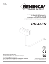
APRICANCELLO SCORREVOLE ELETTROMECCANICO
ELECTROMECHANICAL SLIDING GATE OPENER
ELEKTROMECHANISCHE AUTOMATION FÜR SCHIEBEGITTER
AUTOMATISATION ÉLECTROMÉCANIQUE POUR GRILLES COULISSANTES
ABRECANCELA ELECTROMECANICO PARA CORREDERAS
ELEKTROMECHANICZNY, POSUWOWY OTWIERACZ BRAM
Libro istruzioni e catalogo ricambi
Operating instructions and spare parts catalogue
Betriebsanleitung und Ersatzteilliste
Livret d’instructions et catalogue des pieces de rechange
Libro de instrucciones y catálogo de recambios
Książeczka z instrukcjami i katalog części wymiennych
UNIONE NAZIONALE COSTRUTTORI
AUTOMATISMI PER CANCELLI, PORTE
SERRANDE ED AFFINI

2
Dichiarazione CE di conformità per macchine
(Direttiva 89/392 CE, Allegato II, parte B)
Divieto di messa in servizio
Fabbricante: Automatismi Benincà S.r.l.
Indirizzo: Via Capitello, 45 - 36066 Sandrigo (VI) - Italia
Dichiara che: lʼautomazione per cancelli scorrevoli modello RI.6EV.
• è costruito per essere incorporato in una macchina o per essere assemblato con altri macchinari per costituire una macchina con-
siderata dalla Direttiva 89/392 CE, come modificata;
• non è dunque conforme in tutti i punti alle disposizioni di questa Direttiva;
• è conforme alle condizioni delle seguenti altre Direttive CE:
Direttiva bassa tensione 73/23/CEE, 93/68/CEE.
Direttiva compatibilità elettromagnetica 89/336/CEE, 93/68/CEE.
e che:
• sono state applicate le seguenti (parti/clausole di) norme armonizzate:
EN 55022, EN 61000-3-2, EN 61000-3-3, EN 50082-1, EN 60335-1.
e inoltre dichiara che non è consentito mettere in servizio il macchinario fino a che la macchina in cui sarà incorporato o di cui diverrà
componente sia stata identificata e ne sia stata dichiarata la conformità alle condizioni della Direttiva 89/392 CE e alla legislazione
nazionale che la traspone, vale a dire fino a che il macchinario di cui alla presente dichiarazione non formi un complesso unico con
la macchina finale.
Benincà Luigi, Responsabile legale.
Sandrigo, 01/02/2003.
Declaration by the manufacturer
(Directive 89/392/EEC, Art. 4.2 and Annex II, sub B)
Divieto di messa in servizio
Manufacturer: Automatismi Benincà S.r.l.
Address: Via Capitello, 45 - 36066 Sandrigo (VI) - Italia
Herewith declares that: the operator for sliding gates model RI.6EV.
• is intended to be incorpored into machinery or to be assembled with other machinery to constitute machinery covered by Directive
89/392 EEC, as amended;
• does therefore not in every respect comply with the provisions of this Directive;
• does comply with the provisions of the following other EEC Directives:
Direttiva bassa tensione 73/23/CEE, 93/68/CEE.
Direttiva compatibilità elettromagnetica 89/336/CEE, 93/68/CEE.
and that:
• the following (parts/clauses of) harmonized standards have been applied:
EN 55022, EN 61000-3-2, EN 61000-3-3, EN 50082-1, EN 60335-1.
and furthermore declares that it is not allowed to put the machinery into service until the machinery into which it is to be incorporated
or of which it is to be a component has been found and declared to be in conformity with the provisions of Directive 89/392/EEC and
with national implementing legislation, i.e. as a whole, including the machinery referred to in this declaration.
Benincà Luigi, Responsabile legale.
Sandrigo, 01/02/2003.

Introduzione
Ci congratuliamo con voi per aver scelto il motoriduttore RI.6EV. Tutti gli articoli della vasta gamma Benincà sono
il frutto di una ventennale esperienza nel settore degli automatismi e di una continua ricerca di nuovi materiali
e di tecnologie all’avanguardia. Proprio per questo, oggi siamo in grado di offrire dei prodotti estremamente
affidabili che, grazie alla loro potenza, efficacia e durata, soddisfano pienamente le esigenze dell’utente finale.
Tutti i nostri prodotti vengono costruiti in conformità alle norme vigenti e sono coperti da garanzia. Inoltre, una
polizza R.C. prodotti stipulata con primaria compagnia assicurativa copre eventuali danni a cose o persone
causati da difetti di fabbricazione.
Introduction
Thank you for choosing our RI.6EV ratiomotor. All items in the wide Benincà production range are
the result of twenty-years’ experience in the automatism sector and of continuous research for new
materials and advanced technologies. We are, therefore, in the position to offer higly reliable products
that due to their power, effectiveness and useful life, fully satisfy the final user’s requirements. All our
products are manufactured to the existing standard and are covered by warranty. Possible injury to
people or accidents caused by defects in construction are covered by a civil liability policy drawn up
with one of the major insurance companies.
Einleitung
Wir danken Ihnen dafür, daß Sie sich für den RI.6EV Gitteröffner entschieden haben. Alle Produkte der um-
fangreichen Benincà Produktion sind das Ergebnis der zwanzigjährigen Erfahrungen im Bereich der Automa-
tion und der ständigen Erforschung von neuen Materialien und fortgeschrittenen Technologien. Aus diesem
Grund sind wir heute in der Lage, zuverlässige Produkte anzubieten, die, dank ihren Stärke, Wirksamkeit und
Haltbarkeit, der Anforderungen des Endverbrauchers völlig gerecht werden. Alle Produkte sind nach Normen
gefertigt und durch Garantie gedeckt. Eventuelle Personen- oder Sachschäden, die durch Fertigungsfehler
verursacht werden können, werden durch eine der wichtigsten Versicherungsgesellschaften gedeckt.
Introduction
Nous ne pouvons que féliciter d’avoir porté votre choix sur le moto-réducteur RI.6EV.
Vingt années d’expérience dans le secteur des automatismes ainsi que dans le recherche de nouveaux
matériaux et technologies de pointe, nous ont permis de développer tous les nombreux articles de la
gamme Benincà. Pour ces raisons, nous sommes en mesure de proposer des produits extrémement
fiables et qui grâce à leurs puissances, performances et longévité, répondent aux exigences des
utilisateurs. Tous nos produits sont construits selon les normes en vigueur et sont garantis.
En plus, une police d’assurance responsabilité civile garantie la couverture d’éventuels sinistres à
personnes ou objects causés par les défauts de fabrication.
Introducción
Nos congratulamos con vd. por haber elegido el RI.6EV. Todos los artículos de la vasta gama Benincà son
el fruto de una veinteañal experiencia en el sector de los automatismos y de una continua búsqueda de nue-
vos materiales y de tecnología de vanguardia. Precisamente por esto, hoy nos encontramos en situación de
poder ofrecer productos extremadamentes fiables que, gracias a su potencia, eficacia y duración, satisfacen
plenamente las exigencias del usuario final. Todos nuestros productos están construidos de conformidad con
la norma y están garantizados. Además, una póliza R.C. productos, estipulada con una de las principales
compañías de seguros, cubre eventuales daños a personas o cosas causados por defectos de fabricación.
Wprowadzenie
Gratulujemy Państwu wyboru siłownika RI.6EV.
Cały asortyment szerokiej gamy produktów Benincà jest owocem dwudziestoletniego doświadczenia nabytego w
zakresie automatyzmów oraz ustawicznego poszukiwania nowych materiałów i nowoczesnych technologii.
Z tego też względu jesteśmy dzisiaj w stanie zaoferować państwu nadzwyczaj godne zaufania produkty, które to
dzięki ich skuteczności, sprawności oraz trwałości w pełni zaspakajają wymagania naszych odbiorców.
Wszystkie nasze produkty są produkowane w oparciu o normy i opatrzone są gwarancją. Ponadto, polisa
ubezpieczeniowa o odpowiedzialności cywilnej za produkty, zawarta z jednym z ważniejszych Towarzystw
Ubezpieczeniowych, zapewnia odszkodowanie za szkody poniesione przez rzeczy lub osoby w wyniku wad
produkcyjnych.

6
1. Notizie generali
Per un buon funzionamento dell’automazione per scorrevoli, la porta da automatizzare, dovrà rispondere alle
seguenti caratteristiche:
- la rotaia di guida e relative ruote devono essere opportunamente dimensionate e manutenzionate (onde
evitare eccessivi attriti durante lo scorrimento del cancello.
- durante il funzionamento la porta non deve presentare eccessivi ondeggiamenti.
- la corsa di apertura e chiusura deve essere limitata da un arresto meccanico (secondo normativa di sicurezza
vigente).
1. General information
For an efficient operation of the sliding automatic mechanism, the gate must have the following fea-
tures:
- The guide rail and its wheels must be suitable in size and mantained to prevent gate from excessive
sliding friction.
- When running, gate must not rock excessively.
- Opening and closing stroke must be regulated by a mechanical limit stop (to safety standard in
force).
1. Allgemeine Information
Für eine einwandfreie Funktion der Automation für Schiebegitter, muß das zu automatisierende Gitter folgende
Eigenschaften haben:
- Die Führungsschiene und die Räder müssen entsprechend dimensioniert und periodisch gewartet werden,
um übermäßige Reibungen während dem Gleiten des Gitters zu vermeiden.
- Während des Betriebes darf das Gitter keine übermaßige Schwankungen aufweisen.
- Der Offnungs -und Verschlußhub muß durch einen mechanischen Endanschlag begrenzt werden (nach
geltender Sichereitsnormen).
1. Notice générales
Pour une parfaite automatisation de portails coulissants, vérifier que les suivantes caractéristiques
soient respectées:
- Le rail de guide et les roues devront être correctement dimensionnés et entretenus (pour éviter trop
de frottement pendant le coulissement du portail).
- Pendant le fonctionnement, le portail ne devra pas trop onduler.
- L’ouverture et la fermeture devront être stopées par une bûtée mécanique (selon les normes en
vigueur).
1. Noticias generales
Para un buen funcionamiento de la automatización para correderas, la puerta a automatizar, deberá responder
a las siguientes características:
- el carril de guía y las ruedas correspondientes deben estar correctamente dimensionadas y en perfecto
estado (a fin de evitar excesivas fricciones durante el desplazamiento de la cancela).
- durante el funcionamiento la puerta no debe presentar excesivas ondulaciones.
- los desplazamientos de apertura y cierre deben estar limitados por un tope mecánico (según normativa de
seguridad vigente).
1. Informacje ogólne
Dla sprawnego przeprowadzenia automatyzacji mechanizmów przesuwnych, bramy do zautomatyzowania powinny
spełniać następujące warunki:
- prowadnica z odpowiednimi kółkami powinna posiadać właściwe rozmiary i poddawana być należytej konserwacji
(by uniknąć nadmiernych tarć w trakcie przesuwu skrzydeł bramy),
- w trakcie przesuwu brama nie powinna wykazywać nadmiernych falowań,
- posuw otwierania i zamykania musi być ograniczony przez blokujący chwytak krańcowy, zgodnie z obowiązującą
normą bezpieczeństwa.

7
2. Caratteristiche generali
Automazione per cancelli scorrevoli ad uso civile (peso max. anta 600Kg).
Il RI.6EV è un monoblocco dal design raffinato e di ridotte dimensioni; costituito da un gruppo di alluminio ver-
niciato al cui interno sono stati collocati il motore e un sistema di riduzione irreversibile realizzato con materiali
ad alta resistenza. Gli organi di riduzione sono completamente immersi nell’olio. Il RI.6EV è dotato di finecorsa
con funzionamento a molla. Uno sblocco di emergenza a chiave personalizzata permette la movimentazione
manuale del cancello in mancanza di corrente.
2. General features
Automation for private use sliding gates (max. gate weight 600Kg).
The small and elegant design enbloc RI.6EV consists of a painted aluminium unit containing the motor
and irreversible reduction unit, realized with high-grade materials. The reduction parts are completely
immersed in oil. The RI.6EV has a spring-operated travel-end. A personalized key emergency release
enables manual gate operation in the event of power failure.
2. Allgemeine Eigenshaften
Automation für Schiebegitter im Zivilbereich (max. Gittersgewicht 600Kg).
Der RI.6EV besteht aus einem Block von gefälligem Aussehen und beschränkten Abmessungen; in der lackierten
Aluminiumgruppe befinden sich der Motor und das irreversible Untersetzungssystem, die aus hochbeständigen
Materialien hergestellt werden. Die Untersetzungsorgane arbeiten vollständig im Ölbad. Der RI.6EV verfügt
über Endschalter mit Federbetrieb. Ein Notfallauslöser- mit personalisiertem Schlüssel gestattet die manuelle
Verschiebung des Gitters bei Stromausfall.
2. Caractéristiques générales
Automatisation pour grilles coulissantes à usage civil (poids maximum de la porte 600Kg).
Le RI.6EV est un monobloc au design raffiné et de dimensions réduites; il est constitué d’un groupe en
aluminium verni à l’intérieur duquel ont été placés le moteur et un système de réduction irréversible
réalisé avec des matériaux très résistants. Les organes de réduction cont complètement immergés
dans l’huile. Le RI.6EV est doté de fin de course à ressort. En cas de panne de courant, un déblocage
d’urgence à clé personnalisée permet le déplacement manuel de la grille.
2. Características generales
Automatización para cancelas correderas de uso civil (peso máx. 600Kgs.)
El RI.6EV es un monobloque de diseño refinado y reducidas dimensiones; constituido por un grupo de alu-
minio pintado en cuyo interior han sido colocados el motor y un sistema de reducción irreversible realizado
con materiales de alta resistencia. Los órganos de reducción están completamente sumergidos en aceite. El
RI.6EV está provisto de final de carrera con funcionamiento por muelle. Un desbloqueo de emergencia por
llave personalizada permite el movimiento manual de la cancela en ausencia de corriente.
2. Charakterystyka ogólna
Automytyzowanie bram przesuwnych do użytku prywatnego (maksymalny ciężar skrzydła 600kg.)
RI.6EV to jednokadłubowy, małogabarytowy siłownik o eleganckiej linii, pokryty grupą lakierowanego aluminium z
umieszczonym wewnątrz silnikiem i systemem nienawrotnej redukcji, zrealizowanych z wysoce odpornego materiału.
Mechanizmy redukcyjne są całkowicie zanurzone w oleju. RI.6EV wyposażone są w sprężynowy wyłącznik posuwu.
W przypadku braku napięcia, natychmiastowe odblokowanie przy użyciu klucza osobistego umożliwia ręczną
obsługę bramy.

8
135
235
X
F
T
X≈ 50 per cremagliera in Fe 30x12
X≈ 55 per cremagliera in nylon
X≈ 50 for Fe 30x12 rack
X≈ 55 for nylon rack
X≈ 50 para cremallera Fe 30x12
X≈ 55 para cremallera de nylon
X = 50 dla zębatki z Fe 30x12
X = 55 dla zębatki z nylonu
Fig.1
X≈ 50 für Zahnstange aus Stahl 30x12
X≈ 55 für Zahnstange aus Nylon
X≈ 50 pour cremaillére en acier 30x12
X≈ 55 pour cremaillére en nylon
Dati tecnici
Technical data
Technische Daten Donnees technique
Datos técnicos
Dane techniczne
RI.6EV
Alimentazione
Potenza
Assorbimento
Coppia
Rapporto di riduzione
Classe di isolamento
Interv. termoprotez.
Temp. funzionamento
Peso max. cancello
Velocità apertura
Condensatore
Lubrificazione
Peso
Dimensioni
Feed
Rating
Absorption
Torque
Reduction ratio
Insulation class
Thermoprot. interv.
Working temperature
Max. gate weight
Opening speed
Condenser
Lubrication
Weight
Dimensions
Speisung
Leistung
Verbrauch
Kräftepaar
Untersetzungsverhältnis
Isolierklasse
Eingriff Thermorelais
Betriebstemperatur
Gittersgewicht max.
Öffnungsgeschwindigkeit
Kondensator
Schmierung
Gewicht
Masse
Alimentation
Puissance
Absorption
Couple
Rapport de reduction
Classe d'isolement
Interv. protect. therm.
Temp. fonctionnement
Poids max. portail
Vitesse d'ouverture
Condensateur
Lubrification
Poids
Dimensions
Alimentación
Potencia
Absorción
Par
Relación de reducción
Clase de aislamiento
Interv. termoprotección
Temp. funcionamiento
Peso máx. de la cancela
Velocidad de apertura
Condensador
Lubrificación
Peso
Dimensiones
Napięcie
Moc
Pobór mocy
Moment obrotowy
Przełożenie redukcji
Klasa izolacji
Interw. Termostatu
Temp. podczas pracy
Ciężar max. Bramy
Szybkość otwierania
Kondensator
Smarowanie
Ciężar
Wymiary
230V
280W
1,6A
36Nm
0,042
F
130°C
-20°C / +70°C
600kg
13m/min
16µF
Agip Blasia 100
13kg
215x235xH270mm
Riferimento targhetta sull’azionamento
See operation plate
Siehe Schildchen auf der Motor-Gruppe
Voir la plaque sur le motoréducteur
Referencia tarjeta sobre el accionamiento
Tabliczka ze wskazaniami funkcjonowania

9
3. Messa in posa della piastra di fondazione
Posizionare a terra la piastra di fondazione seguendo le quote della fig.1, mediante n° 4 tasselli a pressione
in acciaio T (in ogni caso la piastra deve essere perfettamente ancorata a terra).
N.B.: Passare sui fori F una guaina adeguata ai cavi di alimentazione dell’attuatore.
3. Foundation slab laying
Secure the foundation slab to the ground with no. 4 steel T pressure inserts to dimensions given in
fig. 1 (it’s important the slab is securely fastened to the ground).
N.B.: Go through holes F with a sheath suitable to the actuator feed cables.
3. Montage der Fundamentplatte
Die Fundamentplatte mit 4 Stahl-Spannschrauben am Boden befestigen (siehe Bild Nr. 1).
Anmerkung: ein entsprechender Mantel für die Versorgungskabelkabel des Aktuators durch die Bohrungen F
stechen.
3. Mise en place de la plaque de fondation
Positionner au sol la plaque de fondation suivant les côtes de la figure 1, avec 4 tirants à pression en
acier T (Il est important que la plaque soit parfaitement fixée au sol).
N.B.: A travers les trous F, faire passer une gaine de protection pour les fils d’alimentation électriques
du motoréducteur.
3. Puesta en posición de la plancha de fundición
Posicionar en tierra la pancha de fundición siguiendo las cotas de la figura 1, mediante 4 tacos de presión de
acero T (en cualquier caso la plancha debe estar perfectamente anclada a tierra).
NOTA: Pasar por los agujeros F un tubo adecuado para los cables de alimentación del operador.
3. Układanie płyty fundamentowej
Płytę fundamentową należy umieścić na ziemi do wysokości wskazanych na rys.1, i umocować ją za pomocą 4
klinów dociskowych ze stali T (w każdym bądź razie płyta musi dobrze przylegać do ziemi).
Uwaga: Przepuścić przez otwory F osłonę kabla do zasilania elektrycznego siłownika.

11
4. Fissaggio cremagliera
4.1 Cremagliera in nylon (fig.2)
Posizionare la cremagliera ad un’altezza di 125 ÷ 126 mm dalla testa del dente cremagliera alla base su cui
andrà fissata la piastra di fondazione; forare e filettare M6 il cancello circa nella mezzeria delle feritoie crema-
gliera. Fissare poi la cremagliera rispettando i punti 4.3 e 4.4.
4.2 Cremagliera in Fe 12x30 mm (fig.2)
Posizionare i distanziali D saldandoli o avvitandoli sul cancello ad un’altezza di 144 ÷ 145 mm dalla piattaforma
su cui andrà fissata la piastra di fondazione dell’attuatore e ad un passo pari alla foratura sulla cremagliera.
Fissare infine la cremagliera rispettando i punti 4.3 e 4.4.
4.3 Rispettare il passo di dentatura anche tra uno spezzone di cremagliera e l’altro; a tale scopo può essere
utile accoppiare un’altro spezzone di cremagliera (vedi fig.2).
4.4 Fissare infine la cremagliera con le viti V, avendo cura, una volta installato l’attuatore, che rimanga ≈1 mm
di gioco tra cremagliera e ruota di trascinamento (vedi fig.3); a tale scopo usufruire delle asole sulla crema-
gliera.
4. Rack fixing
4.1 Nylon rack (fig. 2)
Place the rack at a height of 125 ÷ 126 mm from the base of the foundation slab up to the rack tooth
head; drill and thread M6 the gate approx. in the center line between the rack slots. Now secure the
rack and refer to points 4.3 and 4.4 before proceeding.
4.2 Fe 12x30 mm rack (fig. 2)
Weld or screw the spacer pins D onto the gate at 144 ÷ 145 mm above the base of the foundation ac-
tuator slab and maintain the same pitch as the rack drilling. Now secure the rack and refer to points
4.3 and 4.4 before proceeding.
4.3 Keep the pitch of teeth between the two parts of the rack; the joining with another piece of rack
would make it easier to achieve (see fig. 2)
4.4 Secure the rack with the screws V making sure, once the actuator has been installed, that between
rack and the drive gear there is always approx. 1 mm clearance (see fig. 3); to get this clearance use
the slots on the rack.
4. Befestigung der Zahnstange
4.1 - Zahnstange aus Nylon (Bild Nr. 2)
Die Zahnstange auf eine Höhe von 125 ÷ 126 mm von der Grundfläche der Fundamentplatte bis auf die
Zahnspitze der Zahnstange positionieren; das Gitter durchbohren und ein Gewinde M6 schneiden (ca. mittig
in den Zahnstangennuten). Zahnstange befestigen, den Punkten 4.3 und 4.4. folgend.
4.2 - Zahnstange aus Stahl 12x30 mm (Bild Nr. 2)
Die Distanzstiften D auf eine Höhe von 144 ÷ 145 mm von der Grundfläche der Fundamentplatte in das
Gitter schweißen oder einschrauben. Der Abstand zwischen den Distanzstiften muß dem Abstand zwischen
der, in der Zahnstange gefräste Nuten, entsprechen. Die Zahnstange entsprechend den Punkten 4.3 und 4.4
befestigen.
4.3 - Die Zahnteilung zwischen den Zahnstangenstücken muß außerdem eingehalten werden; zu diesem
Zweck wäre es nützlich ein zweites Zahnstangenstück zu paaren (siehe Bild 2).
4.4 - Durch die Schrauben V, die Zahnstange befestigen; bitte beachten, daß nach der Installation des Aktuators,
ein Spiel von ca. 1 mm zwischen Zahnstange und Zahnrad bleibt (siehe Bild 3). Zu diesem Zweck können die
in der Zahnstange gefrästen Nuten verwendet werden.
4. Fixation de la cremaillére
4.1 Cremaillére en nylon (fig. 2)
Placer la cremaillére à une hauteur de 125 ÷ 126 mm à partir des dents de la cremaillére jusqu’au cîment
sur lequel sera fixé la plaque de fondation; forer et tarauder à M6 le portail, en correspondance du
milieu des dents de la cremaillére en respectant les points 4.3 et 4.4.
4.2 Cremaillére en acier doux 12x30 mm (fig. 2)
Placer les entretoises D en les soudant ou en les visant sur le portail à une hauteur de 144 ÷ 145 mm
du cîment sur lequel sera fixé la plaque de fondation du motoréducteur et au même pas que celui de
la cremaillére. Ensuite fixer la cremaillére, en respectant les points 4.3 et 4.4.
4.3 Respecter le pas de denture même dans le cas de 2 morceaux de cremaillére; pour cela il est
conseillable d’adapter un autre morceau de cremaillére (voir fig. 2).

12
Fig.4
Posizionare in altezza rispetto alla cremagliera e
mettere in bolla.
Place higher than rack and level.
Senkrecht gegenüber der Zahnstange positionieren
und ausrichten.
Réglage en hauteur par rapport à la cremaillére
et mise en niveau horizontal.
Posicionar en altura con respecto a la cremallera
y apretar.
Umieścić na wskazanej wysokości względem zębatki i
ułożyć w pozycji poziomej
V
L
G

14
A
S
1 ÷ 3 cm
G
Fig.6
Fig.5
C
L
Finecorsa appena premuto.
Just pressed limit stop.
Gedrückter Endanschlag.
Fin de course à peine appuyé.
Final de carrera apenas presionado.
Krańcówka dopiero co naciśnięta.
N.B.: La staffa del finecorsa deve essere posizionata in modo tale da permettere l’arresto del cancello senza che questo vada a sbattere contro l’arresto meccanico
N.b. The limit stop flask must be positioned to ensure that the gate stops without knocking against the mechanical stop.
Der Endanschlagtbügel muß so positioniert werden, daß die Sperre des Gitters ohne das Flattern des Schiebegitters gegen den Endschalter A erfolgen kann.
N.B. L’étrier de fin de course doit être positionné de façon à pouvoir arrêter le portail, sans qu’il aille bûter sur le fin de course mécanique.
NOTA: La pletina del final de carrera debe ser colocada de tal forma que permita la parada de la cancela sin que ésta vaya a tocar con el tope mecánico.
Uwaga: Zaczep krańcówki musi być w pozycji takiej by możliwe było zatrzymanie bramy niedopuszczając do jej zderzenia z zaporą mechaniczną.

15
cremallera , ajustarlo actuando sobre los granos G y eventualmente retocar el juego entre la cremallera y el
engranaje (como en la fig. 3). Finalizada esta operación apretar bien los tornillos L.
5. Ustawienie i przymocowanie siłownika (zob. rys.4)
Zdjąć karter po odkręceniu śrubek V. Ustawić zespół z kołem zębatym na środku względem zębatki, ułożyć go w
poziomie przy pomocy trybów G i ewentualnie poprawić luz między zębatką a przekładnią (rys.3). Po zakończeniu
czynności dokręcić dobrze śrubki L.
6. Posizionamento staffe dei finecorsa (fig.5)
Portare manualmente il cancello in apertura lasciando una luce da 1 a 3 cm a seconda del peso del cancello
tra il portone stesso e l’arresto meccanico A; fissare quindi la staffa del finecorsa S mediante i grani G in modo
che il micro finecorsa sia premuto. Ripetere poi l’operazione con il portone in chiusura.
6. Limit stop flask positioning (see fig. 5)
Open manually the gate and leave approximately of 1÷3 cm, depending on gate weight, between gate
and positive mechanical stop A; tighten the limit stop flask S with the grains G to press the limit stop
micro. Repeat the sequence with closing gate.
6. Positionierung der Endanschlagbügeln (Bild 5)
Das Schiebegitter manuell öffnen, damit ein Abstand von 1 bis 3 cm zwischen Gitter und Endschalter A bleibt;
der Endanschlagtbügel S mittels der Stifte G befestigen, bis der Mikroschalter gedrückt wird. Den Vorgang mit
geschlossenem Gitter wiederholen.
6. Positionnement des étriers de fin de course (fig.5)
Ouvrir le portail à la main, en laissant un espace de 1 à 3 cm, selon le poids du portail, entre le portail
et la bûtée mécanique A; ensuite fixer l’étrier de fin de course S avec des vis sans fin G de façon à ce
que le senseur de fin de course soit appuyé. Répeter la même opération avec le portail en phase de
fermeture.
6. Posicionamiento de la pletinas de los finales de carrera (fig.5)
Llevar manualmente la cancela en apertura dejando una luz entre 1 y 3 cms. según el peso de la cancela ,
entre la misma cancela y el tope mecánico A; fijar entonces la pletina del final de carrera S mediante los granos
G de forma que el micro del final de carrera sea presionado. Repetir después la operación con la cancela en
el cierre.
6. Ustawienie zawieszek krańcowego wyłącznika posuwu (rys.5)
Otworzyć ręcznie bramę uchylając ją na szerokość wpadania światła, pomiędzy samą bramą a blokadą mechaniczną
A, od 1 do 3 cm, w zależności od ciężaru bramy; po czym zamocować zawieszki wyłącznika przesuwu S za pomocą
trybów G, w taki sposób aby mikrowyłącznik posuwu był wciśnięty. Powtórzyć czynność podczas zamykania
bramy.
7. Manovra manuale
Per manovrare manualmente il portone, utilizzare lo sblocco come segue (vedi fig.6):
- Inserita la chiave personalizzata C, farla ruotare in senso antiorario e tirare la levetta L.
- Per ristabilire il normale funzionamento richiudere la levetta L ed azionare il cancello manualmente fino ad
ingranamento avvenuto.
7. Manual operation
To operate the gate manually, use the release as follows (see fig. 6):
- once inserted the personalized key C, turn it anticlockwise and pull the lever L.
- to reset the standard operation running, close the lever L and operate the gate manually, until en-
gagement.
7. Manuelle Betätigung
Um das Schiebegitter manuell zu betätigen, muß die Entriegelung wie folgt vorgenommen werden (siehe Bild
6):
- Den Personalschlüssel einstecken und entgegen dem Uhrzeigersinn drehen; den Auslöser L ziehen.

AUTOMATISMI BENINCÀ Srl - Via Capitello, 45 - 36066 Sandrigo (VI) - Tel. 0444 751030 r.a. - Fax 0444 759728
1/17
