
ROBO
V. 010
MANUALE
ISTRU ZIO NI
E CATALOGO
RICAMBI
LIVRET
D’INSTRUCTIONS
ET CATALOGUE
DES
RECHANGES
INSTRUCTIONS
MANUAL
AND SPARE
PARTS
CATALOGUE
ANLEITUNGSHEFT
UND
ERSATZTEIL-
KATALOG
Motoriduttore
elettromeccanico
per cancelli
scorrevoli
Electromechanical
gearmotor for
sliding gates
MANUAL DE
INSTRUCCIONES
Y CATÁLOGO
DE RECAMBIOS
Motorreductor
electromecánico
para cancelas
correderas
Elektromechanischer
Antrieb für
Gleittore
Mototréducteur
électromécanique
pour portails
coulissants
I
GB
F D
E
QUESTO LIBRETTO È DESTINATO SOLO ALL'INSTALLATORE.
L'installazione dovrà essere effettuata solamente da per so na le professionalmente qualifi cato in conformità a quanto previsto
dalla legge n° 46 del 5 marzo 1990 e successive mo di fi che ed integrazioni e nel pieno rispetto delle norme UNI 8612.

ROBO
2
2
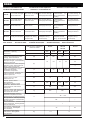
DATI TECNICI - TECHNICAL DATA - DONNÉES TECHNIQUES - TECHNISCHE DATEN - DATOS TÉCNICOS
MODELLI E CARATTERISTICHE -
MODELS AND CHARACTERISTICS
-MOD
È
LES ET CARACTÉRISTIQUES
MODELLE UND EIGENSCHAFTEN
- MODELOS Y CARACTERÍSTICAS
Alimentazione -
Power supply
Alimentation -
Speisung
Alimentaciòn
Assorbimento motore -
Motor absorption
Absorption moteur -
Nenntroment des
Motors -
Absorcion del motor
Assorbimento di linea -
Line input
Absorption de ligne -
Linienaufnahme
Absorcion de la linea
Potenza assorbita -
Absorbed power
Puissance absorbée
Aufgenommene
Leistung -
Potencia absorbida
Grado di protezione -
Protection level
Indice de protection -
Schutzgart
Grado de protección
Condensatore incorporato -
Condenser
built-in -
Condensateur incorporé
Kondensator eingebaut
Condensator incorporado
Coppia -
Torque
- Couple
Drehmoment
-Par
Velocità -
Speed
-Vitesse
Geschwindigkeit
Velocidad de rotación nomina
Spinta max. -
Maximum thrust
Pousèe maximum -
Max. Schub
Empuje max.
Peso max cancello -
Max. weight of gate
Poids max. portail -
Max. Gewicht Tor
Peso maximo de la cancela
Temperatura di esercizio -
Wor king
temperature
-Température de service
Betriebstemperatur
-Temperatura de servicio
Classe di isolamento -
Insulation class
Classe d’isolement -
Isolierungsklasse
Clase de aislamiento
Termoprotezione -
Thermal protection
Protection Thermique -
Wärmeschutz
Termoproteccion
Ciclo di lavoro -
Wor king cycle
Cycle de travail -
Arbeitszyklus
Ciclo de trabajo
Peso motore -
Motor weight
Poids moteur -
Motorgewicht
Peso del motor
Unità di misura -
Unit of measure
Unité de mesure -
Maßeinheit
Unidad de medida
Vac 230 110 230 110 /
50Hz 60Hz 50Hz 60Hz
Vdc 24
(W) 250 230 400 120
(A)
1.2 2.2 1.8 3.4 0.5
5
µF10301430/
IP 44
Nm 10 17 10
m/s 0.18 0.22 0.18 0.22 0.2
N 330 560 330
kg 300 600 400
°C
-20 +50°÷ °
140° /
1
%3080
Kg 10
RO 300
RO1000
RO1010
RO1040
RO1124
I GB F D E
RO 1000
RO 1010
RO 1040
RO 1124
Con central, 300 Kg.
embrague electrónico.
Con central, 600 Kg.
embrague electrónico.
Con central, 600 Kg.
embrague eléctrico.
Con central, 600 Kg.
embrague mecánico.
RoboPlus con central
inteligente, 400 kg.-
encóder (24 V)
RO 300
Mit Steuereinheit,
300 kg, elektronische
Kupplung.
Mit Steuereinheit,
600 kg, elektronische
Kupplung.
Mit Steuereinheit,
600 kg, elektrische
Kupplung.
Mit Steuereinheit,
600 kg, mechanische
Kupplung.
RoboPlus mit
intelligenter Zentrale,
400 kg - (24 V) encoder
Avec centrale, 300 kg,
embrayage électronique.
Avec centrale, 600 kg,
embrayage électronique.
Avec centrale, 600 kg,
embrayage électrique.
Avec centrale, 600 kg,
embrayage mécanique.
RoboPlus avec centrale
intelligente, 400 kg -
ecodeur (24 V).
With central unit, 300 kg
electronic clutch
With central unit, 600 kg
electronic clutch
With central unit, 600 kg
electric clutch
With central unit, 600 kg
mechanical clutch
RoboPlus with an
intelligent unit, 400 kg -
(24 V) encoder
Con centrale, 300 Kg.
frizione elettronica.
Con centrale, 600 Kg.
frizione elettronica.
Con centrale, 600 Kg.
frizione elettronica.
Con centrale, 600 Kg.
frizione meccanica.
Con centrale intelligente
400 Kg. encoder (24 V)
11.7

ROBO
3
VERIFICHE E
PRE LI MI NA RI
I
GB
F
D
E
CHECKING
AND PRELIMINARY
PROCEDURES
CONTRÔLES
PRÉLIMINAIRES
CONTROLES Y
PRELIMINARES
A) Leer atentamente las
instrucciones.
B) Antes de efectuar la
instalación, comprobar que
la estructura de la cancela
sea robusta y adecuada.
C) Comprobar que la
cancela, durante todo su
movimiento, no pre sen te
puntos de roce y que no
exista peligro de
descarrilamiento.
D) Comprobar la presencia
de los costados de
seguridad.
A) Lire attentivement les
instructions.
B) Avant de passer à
l’installation, s’assurer que
la structure de la grille soit
solide et appropriée.
C) S’assurer que la grille
n’ait pas de points de
frottement durant tout le
mouvement et qu’il n’y a pas
de danger de déraillement.
D) S’assurer que les côtés
de sécurité sont présents
A) Read the instructions
carefully.
B) Before starting
installation, ensure that the
structure of the gate is
sturdy and appropriate.
C) Ensure that there is no
point of friction during the
entire movement of the gate.
and that there is no danger
of derailment.
D) Ensure that the safety
side panels are present.
A) Leggere at ten ta men te
le istruzioni.
B) Prima di passare al l'in -
stal la zio ne, ac cer tar si che
la struttura del can cel lo sia
solida ed ap pro pria ta.
C) Accertarsi che il can cel-
lo, durante tutto il suo mo vi -
men to, non su bi sca punti di
attrito e che non vi sia pe ri -
co lo di deragliamento.
D) Accertarsi della pre sen -
za dei franchi di sicurezza.
A) Lesen Sie die
Anleitungen aufmerksam
durch.
B) Vor der Installation
sicherstellen, daß die
Struktur Ihres Tors so li de
und für die Montage
geeignet ist.
C) Sicherstellen, daß das
Tor während der gesamten
Bewegung auf keine
Reibpunkte trifft und keine
Entgleisungsgefahr
besteht.
D) Stellen Sie die Präsenz
der Sicherheitsflanken
sicher.
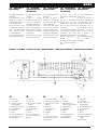
1) Colonnina.
2) Fotocellula.
3) Selettore a chiave o
tastiera digitale.
4) Cartello di avvertenza.
5) Lampeggiatore.
6) Antenna.
7) Robo.
8) Linea di alimentazione.
9) Staffe per fi necorsa.
10) Cremagliera.
I
GB
F D
E
1) Colonne de support
2) Cellule photoélectrique
3) Sélecteur à clé et clavier
digital
4) Panneau
d’avertissement
5) Clignotant
6) Antenne
7) Robo
8) Ligne d’alimentation
9) Pattes de fi n de course
10) Crémaillère
1) Säule
2) Fotozelle
3) Wahlschalter mit
Schlüssel oder Tastfeld
4) Hinweisschild
5) Blinklampe
6) Antenne
7) Robo
8) Speisungsleitung
9) Anschlagbügel
10) Zahnstange
1) Columnita.
2) Fotocélula.
3) Selector de llave o
teclado digital.
4) Placa de advertencia.
5) Luz intermitente.
6) Antena.
7) Robo.
8) Línea de alimentación.
9) Bridas para fi n de
carrera.
10) Cremallera.
1) Column
2) Photocell
3) Key selector or digital
keypad
4) Warning sign
5) Flashing light
6) Aerial
7) Robo
8) Power supply line
9) Stroke end brackets
10) Rack
2x1,5
QUADRO D' INSIEME - OVERALL PICTURE - CADRE GÉNÉRAL - ÜBERSICHTZEICHNUNG - ESQUEMA DE CONJUNTO
2x1
3x1,5
4x1
3x1
1xRG 58
PRÜFUNGEN
UND VORBEREITEN
DE ARBEITEN

ROBO
4
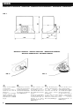
FIG. 1
290
250
88
90
195
FIG. 2
FIG. 3
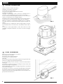
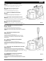
MANOVRA MANUALE - MANUAL OPERATION - MANOEUVRE MANUELLE -
MANUELLE HANDHABUNG - MANIOBRA MANUAL
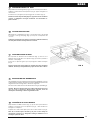
DIMENSIONI D' INGOMBRO - DIMENSIONS - DIMENSIONS D’ENCOMBREMENT - RAUMBEDARF - DIMENSIONES
1) Slide the key cover back.
2) Insert the key and turn it
clockwise by 90° (Fig. 2).
3) Pull out the handle via the
key until it is perpendicular
to the ROBO (Fig. 3).
1) Faire coulisser vers
l’arrière le cache-serrure.
2) Introduire la clé et la
tourner de 90° dans le sens
des aiguilles d’une montre
(Fig. 2).
3) Tirer vers soi la poignée
en agissant d’abord sur la
clé proprement dite de
manière à la placer
perpendiculairement au
ROBO (Fig. 3)
1) Die Abdeckung des
Schlosses zurückschieben.
2) Den Schlüssel
einstecken und um 90°
nach rechts drehen
(Abbildung 2).
3) Den Griff an dem
Schlüssel nach vorne
ziehen, bis er senkrecht zu
Robo steht (Abbildung 3).
1) Hacer deslizar hacia
atrás el cubrecerradura.
2) Introducir la llave y girarla
en el sentido de las agujas
del reloj por 90˚ (Fig. 2).
3) Tirar hacia sí de la
manilla, maniobrando
primero con la misma llave
hasta colocarla
perpendicularmente al
ROBO (Fig. 3).
1) Fare scorrere al l'in die tro
il copriserratura.
2) Inserire la chiave e
ruotarla in senso orario di
90° (Fig. 2).
3) Tirare a se la maniglia
agendo dapprima sulla
chia ve stessa fi no a por tar la
perpendicolare al ROBO
(Fig. 3).
I
GB
F D
E

ROBO
5
FIJACIÓN DE LA PLACA DE BASE
Respetando las medidas externas (Fig. 1), fi jar al suelo la placa de base
mediante 4 resistentes tacos de expansión (Fig. 4), o bien introducir en
hormigón la contraplaca.
Preparar una o varias vainas para el paso de los cables eléctricos (Fig. 4).
Nota. Si la cancela supera los 200 kg de peso o bien trabaja en
condiciones gravosas, es obligatorio sumergir totalmente en el
hormigón la placa de base.
E
I
FISSAGGIO PIASTRA DI BASE
Rispettando le misure d'in gom bro (Fig. 1), fi ssare a terra la piastra di base
me dian te 4 robusti tasselli ad espansione (Fig. 4) oppure annegarla nel
calcestruzzo.
Prevedere una o più guaine per il passaggio dei cavi elet tri ci (Fig. 4).
N.B. Se il cancello supera i 200 Kg di peso, oppure lavora in condizioni
gravose, è obbligatorio annegare totalmente nel calcestruzzo la
piastra di base.
GB
FITTING THE BASE PLATE
Observing the overall dimensions (Fig. 1), fi x the base plate to the ground
by means of 4 strong rawl plugs (Fig. 4) or bury the counterplate in the
concrete.
N.B. If the gate weights over 200 kg or operates in diffi cult conditions,
the base plate must be entirely buried in concrete.
F
FIXATION PLAQUE DE BASE
En respectant les dimensions d’encombrement (Fig. 1), fi xer au sol la
plaque de base à l’aide de 4 vis à expansion (Fig. 4) ou bien noyer dans le
ciment la contre-plaque.
Prévoir une ou plusieurs gaines pour le passage des câbles électriques
(Fig. 4)
N.B. Si la grille pèse plus de 200 kg ou travaille dans des conditions
diffi ciles, il faut noyer complètement la plaque de base dans le béton.
D
BEFESTIGUNG DER GRUNDPLATTE
Die Grundplatte unter Beachtung der Abmessungen (Abbildung 1) mit vier
soliden Expansionsdübeln am Boden befestigen (Abbildung 4) an dem die
mitgelieferte Platte befestigt wird, in den Beton eingießen.
Ein oder mehrere Kabelrohre für die Elektrokabel verlegen (Abbildung 4).
Hinweis. Wenn das Gewicht des Tores 200 kg übersteigt oder wenn
das Tor unter erschwerten Bedingungen arbeitet, muß die
Grundplatte vollständig in Beton eingebettet werden.
FIG. 4

ROBO
6
FIG. 5
FIG. 7
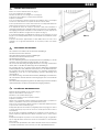
FITTING THE GEARMOTOR
Remove the cover unscrewing the screws (Fig. 5).
Rest the gearmotor on the plate.
Insert the two socket head screws (Fig. 6).
Set the gearmotor to manual operation.
Fit the rack.
Rest the fi rst rack element on the gear (Fig. 7) and lock it to the gate with screws
and spacers, sliding the gate backwards and forwards.
For correct positioning of the other elements, a counter-rack element must be
used (Fig. 8).
There must be a clearance between the rack and gear of at least 1 mm so that
the gate never weighs on the gearmotor.
If the rack adjustment is not suffi cient, the height of the gearmotor can be raised
via the four screws (Fig. 9).
It is important to lock the two socket head screws tightly (Fig. 6) ensuring that
the gearmotor is fi rmly secured to the ground during the whole gate travel.
Position the two limit stop brackets approximately on the rack and move the
gate by hand to fi x them in place.
I
GB
Togliere il coperchio svitando le viti (Fig. 5).
Appoggiare il motoriduttore sulla piastra.
Inserire le due viti a brugola (Fig. 6).
Posizionare il motoriduttore in funzionamento manuale.
Predisporre la cremagliera.
Appoggiare sul l'in gra nag gio il primo elemento di cremagliera (Fig. 7)
e bloc car lo con viti e distanziarli al cancello, facendo scorrere l'anta.
Per un corretto posizionamento degli altri elementi è necessario uti liz za re un
ele men to che fun zio ni da contro cremagliera (Fig. 8).
E' importante che fra cremagliera ed ingranaggio ci sia un certo gioco (almeno
1 mm) in modo che il peso del cancello non gravi mai sul motoriduttore.
Qualora la regolazione con sen ti ta dalla cremagliera non fosse suffi ciente,
è pos si bi le compensare l'altezza del motoriduttore agendo sulle quattro viti
(Fig. 9).
E' im por tan te bloccare ener gi ca men te le due viti a brugola (Fig. 6), as si cu ran-
do si che durante tutta la cor sa del cancello, il motoriduttore sia ben saldo a
terra.
Posizionare in modo approssimativo le due staffe di fi necorsa sulla
cremagliera ed agendo manualmente sul cancello, procedere al fi ssaggio
defi nitivo.
FISSAGGIO MOTORIDUTTORE
FIG. 6
La pagina si sta caricando...

ROBO
8
I
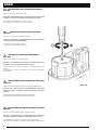
ADJUSTING THE MECHANICAL FRICTION
RO1020
Adjust the screw using a screwdriver (Fig. 10).
Caution - the gearmotor is supplied with the clutch set to maximum;
the torque must be initially reduced.
To increase the torque turn clockwise.
To reduce the torque turn anti-clockwise.
E
EINSTELLUNG DER MECHANISCHEN KUPPLUNG
RO1020
Mit einem Schraubenzieher die Schraube drehen (Abbildung 10).
Achtung, der Antrieb wird mit auf das Maximum eingestellter
Kupplung geliefert; zu Beginn muß das Drehmoment verringert
werden.
Zum Anheben des Drehmoments nach rechts drehen.
Zum Verringern des Drehmoments nach links drehen.
REGOLAZIONE DELLA FRIZIONE MECCANICA
RO1020
Agire con cacciavite sulla vite (Fig. 10).
Attenzione, il motoriduttore viene fornito con la frizione re go la ta al
mas si mo; oc cor re che ini zial men te si di mi nu i sca la coppia.
Per aumentare la coppia ruotare in senso orario.
Per diminuire la coppia ruotare in senso antiorario.
GB
F
RÉGLAGE DE L’EMBRAYAGE MÉCANIQUE
RO 1020
Agir avec un tournevis sur la vis (Fig. 10).
Attention, le motoréducteur est fourni avec l’embrayage réglé au
maximum; au début, il faut en diminuer le couple.
Pour augmenter le couple, tourner dans le sens des aiguilles d’une
montre.
Pour diminuer le couple, tourner dans le sens contraire aux aiguilles
d’une montre.
D
FIG. 10
EINSTELLUNG DER MECHANISCHEN KUPPLUNG
RO1020
Actuar con un destornillador sobre el tornillo (Fig. 10).
Atención, el motorreductor es suministrado con el embrague
regulado al máximo; al empezar, es necesario reducir el par.
Para aumentar el par girar en el sentido de las agujas del reloj.
Para disminuir el par girar en el sentido contrario al de las agujas del reloj.

ROBO
9
I
EINSTELLUNG DER ELEKTRISCHEN KUPPLUNG
RO1010
D
Die Einstellung des Drehmoments erfolgt durch den integrierten Transformator.
Es gibt fünf Positionen mit der Anzeige 30 % bis 100 % (Abbildung 11)
REGOLAZIONE DELLA FRIZIONE ELETTRICA
RO1010
La regolazione della coppia è affi data al trasformatore incorporato.
Vi sono 5 posizioni con in di ca zio ni 30% ÷ 100% (Fig. 11).
ADJUSTING THE ELECTRIC CLUTCH
RO1010
GB
The incorporated transformer regulates the torque.
There are 5 positions marked 30% - 100%. (Fig. 11).
RÉGLAGE DE L’EMBRAYAGE ÉLECTRIQUE
RO 1010
F
Le réglage du couple est assuré par le transformateur incorporé.
Il y a 5 positions avec indications 30% ÷ 100% (Fig. 11).
E
REGULACION DEL EMBRAGUE ELECTRICO
RO1010
La regulación del par es efectuada por el transformador incorporado.
Se encuentran marcadas 5 posiciones con indicaciones 30%÷100% (Fig. 11).
I
REGOLAZIONE DELLA FRIZIONE ELETTRONICA
RO1000 / RO1024
La regolazione della coppia è di tipo elettronico. (Fig. 12)
Attenersi alle istruzioni al le ga te del la centralina elettronica.
EFFETTUARE TUTTE LE REGOLAZIONI RI SPET TAN DO LE NORMATIVE
VIGENTI.
ADJUSTING THE ELECTRONIC CLUTCH
RO1000/RO1024
The torque is electronically adjusted (Fig. 12).
Follow the instructions enclosed with the electronic control unit.
PERFORM ALL ADJUSTMENTS IN COMPLIANCE WITH CURRENT
REGULATIONS.
GB
RÉGLAGE DE L’EMBRAYAGE ÉLECTRONIQUE
RO 1000/RO1024
Le réglage du couple est de type électronique (Fig. 12).
Suivre les instructions fournies avec la centrale électronique.
EFFECTUER TOUS LES RÉGLAGES EN RESPECTANT LES NORMES EN
VIGUEUR.
F
D
EINSTELLUNG DER ELEKTRONISCHEN KUPPLUNG
RO1000/RO1024
Die Einstellung des Drehmoments erfolgt elektronisch (Abbildung 12).
Halten Sie sich an die mit der Steuereinheit gelieferten Anweisungen.
ALLE EINSTELLUNGS-ARBEITEN UNTER BEACHTUNG DER
GELTENDEN VORSCHRIFTEN VORNEHMEN.
E
REGULACION DEL EMBRAGUE ELECTRÓNICO
RO1000/RO1024
La regulación del par es de tipo electrónico (Fig. 12).
Seguir las instrucciones adjuntas de la centralita electrónica.
EFECTUAR TODAS LAS REGULACIONES RESPETANDO LAS NORMAS
VIGENTES.
FIG. 11
FIG. 12

ROBO
10
CATALOGUE DES RECHANGES ERSATZTEILKATALOG CATÁLOGO DE RECAMBIOS
E
D
I
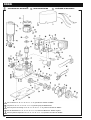
CATALOGO RICAMBI SPARE PARTS CATALOGUE
GB
F
Per i ricambi N° 26 - 36 - 37 - 39 - 25 - 31 - 5 - 32, spe ci fi ca re il modello di "ROBO".
For parts no. 26 - 36 - 37 - 39 - 25 - 31 - 5 - 32, please specify the ROBO model.
Pour les pièces de rechange n° 26 - 36 - 37 - 39 - 25 - 31 - 5 - 32, préciser le modèle de “ROBO”.
Bei den Ersatzteilen 26 - 36 - 37 - 39 - 25 - 31 - 5 - 32, immer das Modell von “ROBO” angeben.
Para las piezas de repuesto N˚ 26 - 36 - 37 - 39 - 25 - 31 - 5 - 32, especifi car el modelo de “ROBO”.
I
GB
F
D
E

ROBO
11
1
2
3
4
5
6
7
8
9
10
11
12
13
14
15
16
17
18
19
20
21
22
23
24
25
26
27
28
29
30
31
32
33
34
35
36
37
38
39
40
41
42
43/44
45
46
47
48
49
50
51
52
53
54
55
56
57
58
59
60
61
62
63
64
65
66
67
68
69
70
71
72
73
74
75
76
BMAM 4567
BMBM 4567
BMFP 4567
PPD1184 4540
BPCO2 4540
BPMS 4540
CM-B 1630
G8X40 5123
MICROI 1617
MO-B 2640
MO-D 2640
PMCSE25
PMCS6 4630
PMCU3 4630
PMCU4 4630
PMCU5 4630
PMC108 4630
PMCS8 4630
PMD0213 4610
PMD0177 4610
PMPS2 4610
V5X105 5102
V8X35C 5102
GOR-O 5501
ROA 12
D8 5102
PMCAC1 4630
V2.9X16 5101
MPFB1 2601
EMRO 4870
V2.9X19 5101
V4.2X9.5 5101
CT200 5320
PMCSS 4630
V4X5 5102
GOR-L 5501
GOR9 5501
V6X12B 5102
V4.2X9.5 5101
PMCAC 4630
CGU6A 5310
C3VF 2015
ERO1000 4870
V2.9X9.5-A 5101
MMCOI 2620
V4.2X13 5101
D8-G 5110
RO8 5120
RO8A 5120
MPFB3 2601
BPC 4540
CFCS 5320
GOR-H 5501
Ancoraggio motore.
Base motore alluminio
Flangia esterna di prot.
Base scatola per centr.
Coperchio motor.
Coperchio scat. centrale.
Sblocco
Chiave con cil.
Grani a taglio 8x40 Zn.
Microinterruttore
Molla di sblocco
Molla per finecorsa.
Rotore motore
Statore
Anello seeger ø 25
Spina elastica
Cuscinetto 6005
Cuscinetto 6203
Cuscinetto 6204
Chiavetta acc. 10x8x40.
Spina cil. acciaio 8x40.
Albero condotto.
Piastra di ancoraggio
Pignone cremagliera zn.
Ruota condotta.
Vite senza fine.
Perno di sblocco
Vite 5x10⁵ zincata
Vite 8x35 zincata
Scheda comando
Condensatore
Distanziale
Trasformatore
Motore 24 dc
Rivetto filettato
Anello compensatore
Vite autofil. 2.9x16
Fascetta
Etichetta morsettiera
Vite autofil. 2.9x19
Vite autofil. 4.2x9.5
Cablaggio terra
Spina sblocco 4x55
Vite M4x5
Guarnizione paraolio
Gommino OR
Vite trilobata 6x12
Vite auofil. 4.2x9.5
Anello compensatore
Guaina PVC
Connettore Alex
Etichetta motoriduttore
Vite autofil. 2.9x9.5
Occhiello isolato
Vite autofil. 4.2x13
Dado M8
Rondella ø8
Rondella spaccata ø8
Fascetta
Copriforo
Cabl. Micro di sicurezza
Guarnizione paraolio
Motor anchoring
Aluminium motor base
External protection flange
Base of central unit box
Motor cover
Central unit box cover
Release
Key with barrel
Slot grub screws
Microswitch
Release spring
Stroke end spring
Motor rotor
Stator
Circlip
Spring pin
Ball bearing
Ball bearing
Ball bearing
Steel key
Steel pin
Driven shaft
Anchoring plate
Pinion for rack
Driven wheel
Worm screw
Release pin
Galvanized screw
Galvanized screw
Control card
Capacitor
Spacer
Transformer
24 V dc motor
Threaded rivet
Compensator ring
2.9x16 screw
Clamp
Terminal board label
2.9x19 screw
4.2x9.5 screw
Earth wiring
Robo end dowel 4x55
4x5 screw
Splash guard seal
O-Ring
6x12 screw
4.2x9.5 screw
Compensator ring
PVC sheath
Alex connector
Gearmotor label
2.9x9.5 screw
Insulated slot
4.2x13 screw
M8 nut
D8 Washer
D8 Split washer
Clamp
Hole cover
Safety microswitch wiring
Splash guard seal
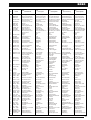
Descrizione
Description
Pos.
Code
Description
I
GB
D
EF
Beschreibung
Ancrage moteur
Base moteur aluminium
Flasque externe de protection
Base boîtier pour centrale
Couvercle motor duc-teuré
Couvercle boîtier centrale
Dblocageé
Cl avec cylindre
é
Goujon à fente 8x40Zn
Microinterrupteur
Ressort de d blocageé
Ressort de fin de course
Rotor moteur
Stator
Bague seeger ø 25
Cheville lastiqueé
Roulement 6005
Roulement 6203
Roulement 6204
Clavette acier 10x8x40
Cheville acier 8x40
Arbre mené
Plaque d’ancrage
Pignon pour cr maillèreé
Roue men eé
Vis sans fin
Pivot de d blocageé
Vis 5x10⁵ zingu eé
Vis 8x35 zingu eé
Carte commande
Condensateur
Entretoise
Transformateur
Moteur 24 V.c.c.
Rivet fileté
Bague compensatrice
Vis 2.9x16
Collier de serrage
Etiquette bornier
Vis 2.9x19
Vis 4.2x9.5
Câblage mise à la terre
Prise d’écoulement
Vis 4x5
Guarniture pare-huile
Joint OR
Vis 6x12
Vis 4.2x9.5
Bague compensatrice
Gaine PVC
Connecteur Alex
Etiquette motor ducteuré
Vis 2.9x9.5
Oeillet isolé
Vis 4.2x13
Ecrou M8
Rondelle D8
Rondelle fendue D8
Collier de serrage
Cache-trou
Câblage du micro. de s c.é
Guarniture pare-huile
Motorverankerung
Grundgestell Motor Al.
Externer Schutzflansch
Gehäuse für Steuereinheit
Motordeckel
Deckel Gehäuse
Entblockung
Schlüssel mit Zylinder
Schneidbolzen 8x40Zn
Mikroschalter
Entblockungsfeder
Feder Anschlag
Rotor Motor
Stator
Seegerring Ø 25
Elastischer Stecker
Lager 6005
Lager 6203
Lager 6204
Stahlschlüssel 10x8x40
Stecker 8x40
Welle Leitung
Verankerungsplatte
Ritzel für Zahnstange.
Rad Leitung
Endlosschraube
Entblockungsknauf
Schraube 5x10⁵ verzinkt
Schraube 8x35 verzinkt
Steuerungsplatine
Kondensator
Distanzstück
Transformator
24 V gs Motor
Niete mit gewinde
Ausgleichsring
Schraube 2.9x16
Schelle
Klemmenbrettekit
Schraube 2.9x19
Schraube 4.2x9.5
Erdverdrahtung
Mündungsstift 4x55
Schraube 4x5
Ölabdichtung
O-Ring
Schraube 6x12
Schraube 4.2x9.5
Ausgleichsring
PVC Mantel
Alex verbinder\1
Getriebemotoretikett
Schraube 2.9x9.5
Schlitz
Schraube 4.2x13
Mutter M8
Unterlegscheibe D8
Unterlegscheibe mit Öffnung D8
Schelle
Lochabdeckung
Verdrahtung des Sicher.
Ölabdichtung
Anclaje motor.
Base motor aluminio.
Brida exterior de protección
.
Base caja para central.
Tapa motor
Tapa caja central.
Desbloqueo
Llave con cil.
Espigas de corte 8x40
Microinterruptor
Resorte de desbloqueo
Resorte para fin de carrera
Rotor motor
Estator
Anillo seeger ø 25
Pasador hendido
Cojinete 6005
Cojinete 6203
Cojinete 6204
Chaveta de acero 10x8x40
Chaveta de acero 8x7x15
Eje conducido
Placa de anclaje
Pi ón para cremallerañ
Rueda conducida
Tornillo sin fin
Perno de desbloqueo
Tornillo 5x10⁵ cincado
Tornillo 8x35 cincado
Tarjeta de mando
Condensador
Separador
Transformador
Motor 24 V CC
Remache de rosca
Anillo compensador
Tornillo 2.9x16
Abrazadera
Etiqueta
Tornillo 2.9x19
Tornillo 4.2x9.5
Cableado tierra
Clavija de desbl. 4x55
Tornillo 4x5
Guarnicion sello de aceiete
Junta torica
Tornillo 6x12
Tornillo 4.2x9.5
Anillo compensador
Vaina de PVC
Connector Alex
Etiqueta motorreductor
Tornillo 2.9x9.5
Argolla aislada
Tornillo 4.2x13
Tuerca M8
Arandela D8
Arandela Grower D8
Abrazadera
Tapa para agujero
Cablado de seguridad
Guarnicion sello de aceiete
Descripción
PMDAC 4610
PPD1185 4540
Gommino OR
O-Ring
Joint OR
O-Ring
Junta torica
D5 5110
Dado M5
M5 nut
Ecrou M5
Mutter M5
Tuerca M5
R12C 5120
V10X12 5102
Vite 10X12 zincata
Galvanized screw
Vis 10X12 zingu eé
Schraube 10x12 verzinkt
Tornillo 10X12 cincado
Rondella ø12
D12 Washer
Rondelle D12
Unterlegscheibe D12
Arandela D12
PMD0886 4610
PMD0885 4610
G6X14 5123
Grani 6x14
Staffa di finecorsa
Staffa di finecorsa
Dowels 6x14 Goujons 6x14 Stiftschrauben 6x14
Tornillos 6x14
Limit switches
Limit switches
Fins de course
Fins de course
Endschalter
Endschalter
Fines de carrera
Fines de carrera
PPD1182 4540
Base scatola per centr.
Base of central unit box Base boîtier pour centrale
Gehäuse für Steuereinheit
Base caja para central.
PPD1183 4540
Tappo
Cap
Bouchon Stöpsel Tapón

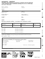
Dati cliente / Client data
Nome e cognome ....................................................
Name and surname
Indirizzo ....................................................................................................................................................................
Address
IMPORTANTE / IMPORTANT
Compilare ad installazione avvenuta e trattenere ad uso garanzia.
To be completed after installation and kept for use as a warranty
Telefono .........................................................................
Telephone
Apparecchiatura tipo ...................................................
Appliance type
Data di installazione ....................................................
Installation date
Installatore ..................................................................
Installer
Indirizzo .....................................................................
Address
Matricola .......................................................................
No. Code
Termine garanzia ...........................................................
Warranty expiry date
Ditta ..............................................................................
Messrs
Telefono .........................................................................
Telephone
Controlli periodici / Periodical check-ups
Data / Date ................................... Descrizione / Description............................................................................
Data / Date ................................... Descrizione / Description............................................................................
Data / Date ................................... Descrizione / Description............................................................................
Data / Date ................................... Descrizione / Description............................................................................
Descrizione materiale installato / Description of the components installed
Da compilare in caso di anomalia (inviare fotocopia della pagina allegandola all'attuatore in riparazione)
To fi ll in case of defect (send copy of the page enclosed with the actuator to be repaired)
Difetto segnalato / Defect ...........................................................................................................................................
..................................................................................................................................................................................
Parte riservata alla NICE spa per comunicazioni al cliente
Space reserved for NICE spa to communicate with the Clients
Data registrazione ..................................Data riparazione............................... N. Riparazione ..............................
Date of registration Repair date Repair number
Parti sostituite .......................................................................................................................................................
Parts replaced
Note / Note....................................................................... Firma tecnico / Technician signature
.........................................................................................
........................................................................................ .................................................................
A termini di legge ci riserviamo la proprietà di questo manuale con divieto di riprodurlo o di renderlo co mun que noto a terzi o a ditte
concorrenti senza nostra au to riz za zio ne.
carta riciclata 100% recycled paper 100% papier recycle 100% 100% Altpapier 100% papel reciclado
ISTRO 4865 REV.010 del 13/01/05
Centrale di comando Radio Dispositivi di sicurezza Note
Control box Radio Safety devices Notes
-
 1
1
-
 2
2
-
 3
3
-
 4
4
-
 5
5
-
 6
6
-
 7
7
-
 8
8
-
 9
9
-
 10
10
-
 11
11
-
 12
12


Nice Automation Robo Manuale del proprietario
- Categoria
- Gate Opener
- Tipo
- Manuale del proprietario
in altre lingue
Documenti correlati
Altri documenti
-
Telcoma ACE Instruction Handbook Manual
-
Genius Falcon Manuale utente
-
Genius Falcon 14C Installation Instructions Manual
-
-
-
Elvox ES series Manuale utente
-
-
Honeywell CT200 Manuale del proprietario