La pagina si sta caricando...

2
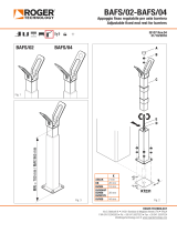
BI/004
con asta da 2,2 m a 2,80 m
with boom from 2,2 to 2,8 m
BI/004
con asta da 3 m
with boom of 3 m
BI/004
con asta da 4 m
with boom of 4 m
AG/001/PC
KB/001/PC
asta fino a 3 m
with boom up to 3 m
BI/001/PC
asta fino a 3 m
with boom up to 3 m
SP48/01
VERDE
GREEN
GRÜN
VERT
VERDE
VERDE
SP61/01
BLU
BL
UE
BLA
U
BLEU
AZUL
AZUL
2 m 2 m
1
2
1
3
IT Nr. 2 molle Ø61 art. SP61/01 installate di fabbrica.
EN Nr. 2 springs Ø61 art. SP61/01 fitted at the factory.
DE Nr. 2 Federn Ø61 art. SP61/01 - im Werk installiert.
FR Nr. 2 ressorts Ø61 art. SP61/01 - installé à l’usine.
ES
Nr. 2 muelles Ø61 art. SP61/01 - instalado en la fábrica.
PT Nr. 2 molas Ø61 art. SP61/01 - instalado na fábrica.
IT È obbligatorio l’uso dell’appoggio fisso.
EN The fixed end rest must be used.
DE Die Verwendung der festen Auflage ist Pflicht.
FR L’utilisation de l’appui fixe est obligatoire.
ES Es obligatorio utilizar el apoyo fijo.
PT É obrigatório o uso do suporte fixo.
IT È obbligatorio l’uso dell’appoggio fisso regolabile con
magnete integrato BAFS/05.
EN The adjustable fixed end rest with integrated magnet
BAFS/05 must be used.
DE Die Verwendung der einstellbaren festen Auflage mit
integriertem Magnet BAFS/05 ist Pflicht.
FR L’utilisation de l’appui fixe réglable avec aimant intégré
BAFS/05 est obligatoire.
ES Es obligatorio utilizar el apoyo fijo ajustable con imán
integrado BAFS/05.
PT É obrigatório o uso do suporte fixo ajustável com ímã
integrado BAFS/05.
2 2
3
3
Per la scelta della molla, le aste si intendono complete di gomma antiurto e strip LED.
For the choice of spring, the booms are understood as complete with shock-resistant rubber and LED strips.
Für die Wahl der Feder, die Schlagbäume verstehen sich einschließlich dem Gummi, um Stöße abzufangen und LED-Strip.
Pour le choix du ressorts, les barres sont dotées de caoutchouc antichoc et bande LED.
Para elegir la muella, las astas llevan el tope de goma y la tira de LED.
Para escolher a mola, as hastes estão dotadas de borracha antirroubo a tira LED.

3
G
r
a
s
s
o
G
r
e
a
s
e
1
2
3
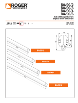
TE M14x60
TE M14x60
Sinistra (SX)
Lef
t (LT)
Destra (DX)
Right (RT)
TE M14x45
1
2
BARRIERA INSTALLATA A DESTRA
(Vista lato sportello di ispezione)
BARRIERA INSTALLATA A SINISTRA
(Vista lato sportello di ispezione)
B
B
A
A
-
+
45° >45°
<45°
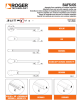
BI/004

4
AG/001/PC • KB/001/PC
A
A
B
B
G
r
a
s
s
o
G
r
e
a
s
e
A
A
B
B
G
r
a
s
s
o
G
r
e
a
s
e
45°
>45°
<45°
B
B
A
A
-
+
3
C
C
3
3
C
C
3
3
2
2
1
1
3
AABBCC
3
2
2
1
1
3
AABBCC
BARRIERA INSTALLATA A DESTRA
(Vista lato sportello di ispezione)
BARRIERA INSTALLATA A SINISTRA
(Vista lato sportello di ispezione)

5
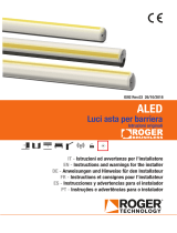
BI/001PC
BARRIERA INSTALLATA A DESTRA
(Vista lato sportello di ispezione)
BARRIERA INSTALLATA A SINISTRA
(Vista lato sportello di ispezione)
A
A
B
B
G
r
a
s
s
o
G
r
e
a
s
e
A
A
B
B
G
r
a
s
s
o
G
r
e
a
s
e
B
B
A
A
-
+
3
C
C
3
3
C
C
3
3
2
2
1
1
3
AABBCC
3
2
2
1
1
3
AABBCC
45°
<45°
>45°

6
IT
FR
EN
DE
Installazione e regolazione della molla - Installing and adjusting the spring
Installation und Einstellung der Feder - Installation et réglage du ressort
Instalación y ajuste del muelle - Instalação e ajuste da mola
Serie BI/004
1. Scegliere il senso di apertura desiderato.
2. Sbloccare la barriera e portare l’asta in posizione verticale di completa apertura.
3. Scegliere la molla più adeguata (vedi tabella).
4. Le molle sono identificate da un colore. La parte colorata deve essere posizionata verso
l’alto: verde - le molle Ø48 (SP48/01); blu - le molle Ø61 (SP61/01).
5. Svitare la vite superiore TE M14x60 della molla (vista lato colorato superiore) ed
accantonarla.
6. Svitare la vite TE M14x45 dal bilanciere e fissare la molla con la medesima vite. La vite
M14x45 sul lato opposto deve rimanere fissata sul bilanciere:
- Per barriere con apertura a sinistra usare i fori SX1 oppure SX2.
- Per barriere con apertura a destra usare i fori DX2 oppure DX3.
7. Fissare la molla alla struttura fissa, sul traverso in acciaio della barriera, con le viti TE
M14x60 incluse nella confezione.
Serie AG/001/PC-KB/001/PC-BI/001PC
1. Nelle automazioni AG/001/PC-KB/001/PC-BI/001PC sono installate di fabbrica 2 molle
Ø61 SP61/01 per aste cilindriche fino a 3 metri.
2. Nel caso di sostituzione, rimuovere le molle.
3. Fissare le NUOVE molle avvitandole sui fori del bilanciere predisposti usando le viti in
dotazione.
4. I fori di fissaggio corretti sono C-3. I fori A/B - 1/2 sono per predisposizioni future.
5. Fissare le molle alla struttura fissa, sul traverso in acciaio della barriera, con le viti in
dotazione.
• Ingrassare gli snodi con grasso al LITIO (EP LITIO) . E’ disponibile su richiesta l’articolo RS/
GR1/100: barattolo di grasso al Litio da 100 gr.
• Regolare la tensione della molla allentando i dadi [A]
• Ruotando la molla [B] in senso orario si diminuisce la tensione, in senso antiorario si
aumenta la tensione.
• Portare manualmente l’asta a 45° e rilasciarla. Se l’asta sale, ridurre la tensione della
molla. Se l’asta scende, aumentare la tensione della molla.
• Quando la regolazione della molla è ottimale, stringere con forza i dadi [A].
BI/004 Series
1. Select the desired opening direction.
2. Unlock the barrier and move the boom into the completely open vertical position.
3. Select the most suitable spring.
4. The springs are colour coded for identification. The coloured part of the spring must always
be at the top: green - Ø48 springs (SP48/01); blue - Ø61 springs (SP61/01).
5. Unscrew the upper screw TE M14x60 of the spring (viewed from the top coloured side).
6. Unscrew the screw TE M14x45 from the linkage lever and fasten the spring with the same
screw:
- For barriers with left-side opening, use the SX1 or SX2 holes.
- For barriers with right-side opening, use the DX2 or DX3 holes.
7. Fasten the springs to the fixed structure, on the steel cross bar of the barrier, using the
screws TE M14x60 included in the package.
AG/001/PC-KB/001/PC-BI/001PC Series
1. The system AG/001/PC-KB/001/PC-BI/001PC is fitted in the factory with two SP61/01
balancer springs Ø61, which are suitable for cylindrical booms up to 3 metres in length.
2. Remove the springs to be replaced.
3. Fit the NEW springs, fastening to the mounting holes on the steel linkage lever using the
screws included.
4. The fastener holes are indicated by the letter C and the number 3. Holes A/B and 1/2 are
for future variants.
5. Secure the springs to the fixed structure by fastening to the steel cross bar of the barrier
using the screws included.
• Lubricate the pivot points with lithium based grease (EP LITIO). Available upon request,
article RS/GR1/100: 100 g can of lithium grease.
• To adjust the spring tension, loosen the nuts [A].
• Then turn the spring [B] clockwise to reduce the tension or anticlockwise to increase tension.
• Lift the boom manually to an angle of 45° and let go. If the boom rises, reduce the spring
tension. If the boom drops, increase the spring tension.
• Once the spring tension is correct, tighten the nuts securely [A].
Serie AG/001/PC-KB/001/PC-BI/001PC
1. In der automatischen Schranke AG/001/PC-KB/001/PC-BI/001PC sind werkseitig zwei
Ausgleichsfedern installiert vom Typ SP61/01 für runde Schrankenbäume bis 3 Meter.
2. Die auszutauschenden Federn entnehmen.
3. Die NEUEN Federn befestigen, indem man sie mit den mitgelieferten Schrauben in den
vorhandenen Bohrungen an den Kipphebel aus Stahl schraubt.
4. Die Befestigungsbohrungen sind die Nummer C-3. Die Bohrungen Nummer A/B und 1/2
sind für zukünftige Vorrüstungen.
5. Die Federn an der festen Struktur, am Querträger aus Stahl der Schranke, mit den
mitgelieferten Schrauben befestigen.
Serie BI/004
1. Die gewünschte Öffnungsrichtung wählen.
2. Die Schranke freigeben und den Schlagbaum senkrecht in vollständig geöffnete Stellung bringen.
3. Die passendste Feder wählen.
4. Die Federn sind durch eine Farbe gekennzeichnet. Der farbige Teil muss nach oben positioniert
werden: grün - die Federn Ø48 (SP48/01); blau - die Federn Ø61 (SP61/01).
5. Die obere Schraube TE M14x60 der Feder abschrauben.
6. Die Schraube TE M14x45 von dem Kipphebel abschrauben und die Feder mit dieser
Schraube befestigen:
- Für Schranken mit Linksöffnung, die Bohrlöcher SX1 oder SX2 verwenden.
- Für Schranken mit Rechtsöffnung, die Bohrlöcher DX2 oder DX3 verwenden.
7. Die Feder mit den mitgelieferten Schrauben an der festen Struktur auf dem Stahlquerträger
der Schranke mit den beigepackten Schrauben TE M14x60 befestigen.
• Die Gelenke mit LITHIUM-Fett (EP LITHIUM) schmieren. Auf Wunsch ist der Artikel RS/
GR1/100 erhältlich: 100 g Dose Lithium-Fett.
• Die Spannung der Feder einstellen, indem man die Muttern [A] lockert.
• Durch Drehen der Feder [B] im Uhrzeigersinn verringert man die Spannung, gegen den
Uhrzeigersinn wird die Spannung erhöht.
• Den Schlagbaum von Hand auf 45° bringen und loslassen. Wenn der Baum nach oben geht,
die Spannung der Feder verringern. Wenn der Baum sinkt, die Spannung der Feder erhöhen.
• Wenn die Einstellung der Feder optimal ist, die Muttern [A] fest anziehen.
Sèrie BI/004
1. Choisir le sens d’ouverture souhaité.
2. Débloquer la barrière et porter la barre en position verticale d’ouverture totale.
3. Choisir le ressort le plus approprié.
4. Les ressorts sont identifiés par une couleur. La partie colorée doit être dirigée vers le haut:
vert - les ressorts Ø48 (SP48/01); bleu - les ressorts Ø61 (SP61/01).
5. Dévisser la vis supérieure TH M14x60 du ressort (vue côté coloré supérieur).
6. Dévisser la vis TH M14x45 du balancier et fixer le ressort avec la même vis :
- Pour barrières avec ouverture à gauche, utiliser les trous G1 ou G2.
- Pour barrières avec ouverture à droite, utiliser les trous D2 ou D3.
7. Fixer le ressort à la structure fixe, sur la traverse en acier de la barrière, avec les vis TH
M14x60 fournies dans l’emballage.
Serie AG/001/PC-KB/001/PC-BI/001PC
1. Deux ressorts d’équilibrage AG/SP/61 pour barres cylindriques jusqu’à 3 mètres sont
installés en usines.
2. En cas de remplacement des ressorts, Retirer les ressorts à remplacer.
3. Fixer les ressorts neufs en les vissant au balancier en acier dans les trous prédisposés à
l’aide des vis fournies.
4. Les trous de fixation sont le numéro C3. Les trous A/B et 1/2 servent aux prédispositions futures.
5. Fixer les ressorts à la structure fixe, sur la traverse en acier de la barrière, à l’aide des vis
fournies.
• Graisser les articulations à la graisse au LITHIUM (EP LITHIUM). L’article RS/GR1/100 est
disponible sur demande : pot de graisse au lithium de 100 g.
• Régler la tension du ressort en desserrant les écrous [A].
• Tourner le ressort [B] dans le sens des aiguilles d’une montre pour réduire la tension, dans
le sens inverse pour augmenter la tension.
• Porter à la main la barre à 45° puis la relâcher. Si la barre monte, réduire la tension du
ressort. Si la barre descend, augmenter la tension du ressort.
• Quand le réglage du ressort est optimal, serrer fermement les écrous [A].

ROGER TECHNOLOGY
Via S. Botticelli 8 • 31021 Bonisiolo di Mogliano Veneto (TV) • ITALIA
P.IVA 01612340263 • Tel. +39 041.5937023 • Fax. +39 041.5937024
info@rogertechnology.com • www.rogertechnology.com
1/8