La pagina si sta caricando...

3
FIG. 3
FIG. 4
MIN 700 mm / MAX 970 mm
F1
F2
F3
PROG TEST
+
-
BATTERY (+)
RECEIVER CARD
BATTERY CHARGER
SEC2
ENC2
ENC1
LOCKS
LED LIGHT
SEC1
BATTERY (-)
123456
Y
X
M
Z
78
COM
COM
+24V
+LAM
COM
LNA
LNB
+SC
10 11 12 13 14 15 16 17 18 19 20
+LUCI
ST
COM
COS
FT
COM
ANT
21 22 23 24 25
COM
PED
PP
CH
AP
28 29 30 31 32
ORO
33
COM
3426 27
9
+ES
+ES
COM
COM
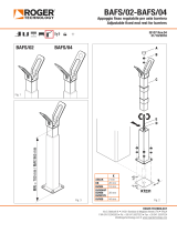
CTRL
SI31
r3.20
COMPATIBILE DA:
COMPATIBLE FROM:
F
F
F
G
G
F
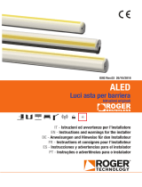
L’asta è puramente indicativa.
The boom is indicative only.
Das Schlagbaum ist nur indikativ.
La barre est purement indicative.
La asta es meramente indicativa.
A hasta é puramente indicativa.

ROGER TECHNOLOGY
Via S. Botticelli 8 • 31021 Bonisiolo di Mogliano Veneto (TV) • ITALIA
P.IVA 01612340263 • Tel. +39 041.5937023 • Fax. +39 041.5937024
info@rogertechnology.com • www.rogertechnology.com
1. Predisporre lo scavo e la canalina per il passaggio del cavo di alimentazione
della ventosa magnetica.
2. Svitare le viti e togliere il tappo dell’asta [A].
3. Tagliare la gomma antiurto a misura, come indicato in fig. 1 e sfilarla dall’asta (parte
di gomma vicino alla punta dell’asta).
4. Inserire all’interno del profilo in alluminio la piastra quadrata [B].
5. Assemblare e fissare la piastra [C] della ventosa magnetica all’asta, con la vite in
dotazione.
6. Infilare la gomma antiurto nel profilo di alluminio e chiudere il tappo [A] sull’asta.
7. Fissare l’appoggio fisso [D] sulla piastra di base KT231 (fig. 2).
8. Inserire la parte regolabile [E] dell’appoggio nella parte fissa [D].
9. Regolare l’altezza e fissare l’appoggio fisso con le 4 viti TCBEI M8x16 [F] in
dotazione.
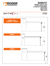
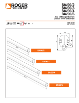
10. Forare e filettare con maschio M8. Fig. 3
11. Fissare le viti TCBEI M8x16 [G] per la messa in sicurezza dell’appoggio fisso.
12. Se necessario, regolare la posizione dell’appoggio fisso agendo sulle asole della
piastra di base. L’asta e il basamento devono risultare perpendicolari tra loro.
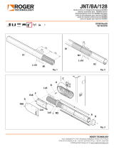
13. Verificare, che quando completamente chiusa, l’asta sia perfettamente in bolla e
appoggiata alle protezioni in gomma dell’appoggio fisso (fig. 4).
14. Collegare l’alimentazione della ventosa magnetica ai morsetti COM e +ES della
centrale di comando (fig. 3). Compatibile con la revisione r3.20 / produzione
SI31 e successive.
1. Prédisposer l’excavation et le conduit pour le passage du câble
d’alimentation de la ventouse magnétique.
2. Dévisser les vis et retirer le bouchon de la barre [A].
3. Couper le caoutchouc antichoc à la bonne mesure, comme indiqué en fig. 1 et le
défiler de la barre (partie de caoutchouc près du bout de la barre).
4. Introduire à l’intérieur du profilé en aluminium la plaque carrée [B].
5. Assembler et fixer la plaque [C] de la ventouse magnétique sur la barre, avec la
vis fournie.
6. Enfiler le caoutchouc antichoc dans le profilé en aluminium et fermer le bouchon
[A] sur la barre.
7. Fixer l’appui fixe [D] sur la plaque de base KT231 (fig. 2).
8. Introduire la partie réglable [E] de l’appui dans la partie fixe [D].
9. Régler la hauteur et fixer l’appui fixe avec les 4 vis à tête cylindrique bombée à six
pans creux M8x16 [F] fournies.
10. Percer et fileter au taraud M8. Fig. 3
11. Fixer les vis à tête cylindrique bombée à six pans creux M8x16 [G] pour la mise en
sécurité de l’appui fixe.
12. Au besoin, régler la position de l’appui fixe en agissant sur les anneaux de la plaque
de base. La barre et le socle doivent être perpendiculaires.
13. Vérifier que, une fois entièrement fermée, la barre soit parfaitement à niveau et
repose sur les protections en caoutchouc de l’appui fixe (fig. 4).
14. Brancher l’alimentation de la ventouse magnétique aux bornes COM et +ES de
la centrale de commande (fig. 3). Compatible avec révision r3.20 / lot de
fabrication SI31 et suivant.
1. Prepare the groove and duct for the magnetic suction cup supply cable.
2. Loosen the screws and remove the cap from the boom [A].
3. Cut the protective rubber to the required length (as shown in fig.1), and
remove it from the boom (part of rubber near the tip of the rod).
4. Insert the square plate [B] in the aluminium profile.
5. Assemble the plate [C] of the magnetic suction cup and fix it to the boom, using
the screw supplied.
6. Insert the protective rubber in the aluminium profile and replace the cap [A] on the
boom.
7. Fix the fixed end rest [D] to the KT231 base plate (fig.2).
8. Insert the adjustable part [E] of the rest in the fixed part [D].
9. Adjust the height and then block the fixed end rest in place with the 4 screws TCBEI
M8x16 [F] supplied.
10. Bore and thread with a male M8 (fig.3).
11. Tighten the screws TCBEI M8x16 [G] to ensure the fixed end rest is safely blocked.
12. If necessary, adjust the position of the fixed end rest by means of the slots on the
base plate. The boom and base must be at right angles to each other.
13. Make sure that, when it is fully closed, the boom is perfectly level and resting on the
rubber guards of the fixed end rest (fig.4).
14. Connect the magnetic suction cup to terminals COM and +ES of the control
unit (fig.3). Compatible with upgrade r3.20 / production batch SI31 and
following.
1. Preparar el hueco y el canal para el paso del cable de alimentación de la
ventosa magnética.
2. Desenroscar los tornillos y quitar el tapón del asta [A].
3. Cortar el tope de goma a medida, como se indica en la fig. 1, y sacarlo del asta (parte
de goma cerca de la punta de la asta).
4. Introducir dentro del perfil de aluminio la placa cuadrada [B].
5. Montar y fijar la placa [C] de la ventosa magnética al asta, con el tornillo suministrado.
6. Introducir el tope de goma en el perfil de aluminio y cerrar el tapón [A] en el asta.
7. Fijar el apoyo fijo [D] en la placa de base KT231 (fig. 2).
8. Introducir la parte regulable [E] del apoyo en la parte fija [D].
9. Regular la altura y fijar el apoyo fijo con los 4 tornillos Allen de cab. convexa M8x16
[F] suministrados.
10. Taladrar y roscar con macho M8. Fig. 3
11. Fijar los tornillos Allen de cab. convexa M8x16 [G] para la puesta en seguridad del
apoyo fijo.
12. Si es necesario, regular la posición del apoyo fijo accionando las ranuras de la placa
de base. El asta y la base deben estar perpendiculares entre sí.
13. Comprobar que, cuando esté completamente cerrada, el asta esté perfectamente
nivelada y apoyada en las protecciones de goma del apoyo fijo (fig. 4).
14. Conectar la alimentación de la ventosa magnética en los terminales COM y +ES
de la centralita (fig. 3). Compatible con revisión r3.20 / lote de producción
SI31 y posterior.
1. Aushub und Kanal für den Durchzug des Stromkabels des magnetischen
Saugnapfs vorbereiten.
2. Die Schrauben lösen und den Deckel des Schlagbaums [A] entfernen.
3. Den stoßfesten Gummi zuschneiden wie aus Abb. 1 ersichtlich und aus dem
Schlagbaum ziehen (Teil des Gummis in der Nähe der Stangenspitze).
4. Die quadratische Platte [B] in das Aluminiumprofil einsetzen.
5. Die Platte [C] des magnetischen Saugnapfs mit der beigepackten Schraube am
Schlagbaum befestigen.
6. Den stoßfesten Gummi in das Aluminiumprofil einsetzen und den Deckel [A] am
Schlagbaum anbringen.
7. Die feste Auflage [D] an der Grundplatte KT231 befestigen (Abb. 2).
8. Den verstellbaren Teil [E] der Auflage in den starren Teil [D] einsetzen.
9. Die Höhe einstellen und die feste Auflage mit den beigepackten 4 Schrauben mit
Halbrundkopf und Innensechskant M8x16 [F] befestigen.
10. Mit einem Gewindebohrer M8 Löcher bohren. Abb. 3.
11. Für einen sicheren Halt der festen Auflage die Schrauben mit Halbrundkopf und
Innensechskant M8x16 [G] arretieren.
12. Gegebenenfalls die Position der festen Auflage über die Langlöcher der Grundplatte
verstellen. Schlagbaum und Fundament müssen einen rechten Winkel zueinander bilden.
13. Prüfen, ob der komplett geschlossene Schlagbaum absolut plan ist und am
Gummischutz der festen Auflage aufliegt (Abb. 4).
14. Die Stromversorgung des magnetischen Saugnapfs an die Klemmen COM und
+ES des Steuergeräts anschließen (Abb. 3). Kompatibel mit Revision r3.20 /
Produktionslos SI31 und anschließend.
1. Prepare a escavação e a conduta para a passagem do cabo de alimentação
da ventosa magnética.
2. Desenrosque os parafusos e retire o tampão da haste [A].
3. Corte a borracha antichoque conforme indicado na fig. 1, e desenfie-a da haste
(parte de borracha perto da ponta da haste).
4. Insira no interior do perfil de alumínio a chapa quadrada [B].
5. Monte e fixe a chapa [C] da ventosa magnética à haste, com o parafuso fornecido.
6. Enfie a borracha antichoque no perfil de alumínio e feche a tampa [A] na haste.
7. Fixe o suporte fixo [D] na chapa de base KT231 (fig. 2).
8. Insira a parte ajustável [E] do suporte na parte fixa [D].
9. Ajuste a altura e fixe o suporte fixo com os 4 parafusos TCBEI M8x16 [F] fornecidos.
10. Perfure e enrosque com o macho M8. Fig. 3
11. Fixe os parafusos TCBEI M8x16 [G] para a montagem do suporte fixo.
12. Se necessário, ajuste a posição do suporte fixo atuando nas fendas da chapa de
base. A haste e a base devem estar perpendiculares entre elas.
13. Verifique se, quando completamente fechada, a haste está perfeitamente em nível
e encostada às proteções de borracha do suporte fixo (fig. 4).
14. Ligue a alimentação da ventosa magnética aos prensadores COM e +ES da unidade
de controlo (fig. 3). Compatível com revisão r3.20 / lote de produção SI31 e
posteriores.
Installazione appoggio fisso regolabile con ventosa magnetica per barriere
Adjustable fixed end rest with magnetic suction cup for barriers
Installation der einstellbaren festen Auflage mit magnetischem Saugnapf für Schranken
Installation appui fixe réglable avec ventouse magnétique pour barrières
Instalación de apoyo fijo regulable para barreras con ventosa magnética
Instalação do suporte fixo ajustável para barreiras com ventosa magnética
IT
EN
DE
FR
ES
PT
/