
364234
Audio Kit
Manuale installatore • Installation manual
LE11157AA01PC19W17

2
Attenzione: Le operazioni di installazione, configurazione, messa in servizio e manutenzione devono
essere effettuate da personale qualificato.
Caution: Installation, configuration, starting-up and maintenance must be performed by qualified
personnel
Attention: Les opérations d’installation, de configuration, de mise en service et d’entretien doivent
être confiées à un personnel qualifié.
Achtung: Die Installation, Konfiguration, Inbetriebnahme und Wartung dürfen nur von qualifizierten
Fachleuten vorgenommen werden
Atención: Las operaciones de instalación, configuración, puesta en servicio y mantenimiento han de
ser efectuadas por personal cualificado
Opgelet: Laat de installatie, de configuratie, de inbedrijfstelling en het onderhoud door gekwalificeerd
personeel verrichten
Atenção: As operações de instalação, configuração, colocação em serviço e manutenção devem ser
realizadas por pessoal qualificado

Audio - Kit
3
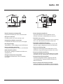
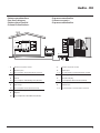
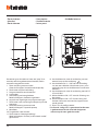
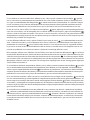
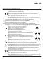
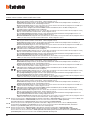
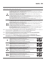
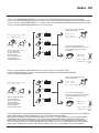
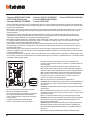
• Vecchio impianto a campanello
Impianto esistente con 3 fili e sola chiamata.
• Old system with bell
Existing system with 3 wires and just call.
• Ancienne installation a sonnette
Installation existante à 3 fils et un seul appel.
• Alte klingelanlage
Vorhandene 3-Leiter Anlage nur mit Ruffunktion.
• Vieja instalación con timbre
Instalación existente con 3 hilos y una llamada.
• Oude deurbelinstallatie
Bestaande 3-aderige installatie met alleen een
oproepfunctie.
• Antiga instalação em campaínha
Instalação existente com 3 fios e somente
chamada.
• Nuovo impianto citofonico
Impianto realizzato senza modifiche ai 2 fili
esistenti: chiamata, videocitofono e serratura.
• New door entry system
System made without modifications to the 2 existing
wires; call, video handset and electric door lock.
• Nouvelle installation phonique
Installation réalisée sans modifications sur les 2 fils
existants: appel, vidéophone, et serrure électrique.
• Neue haustelefonanlage
Anlage ohne Änderungen an den vorhandenen 2 Leiter:
Ruffunktion, Gegensprechanlage und elektrisches Schloss.
• Nueva instalación interfónica
Instalación realizada sin las modificaciones a los 2 hilos
existentes: llamada, videoportero y cerradura eléctrica.
• Nieuwe deurtelefooninstallatie
Installatie aangelegd zonder wijzigingen aan de
2 bestaande aders: oproep, beeldhuistelefoon en
elektrisch deurslot.
• Nova instalação do intercomunicador
Instalação realizada sem modificar os 2 fios existentes:
chamada, intercomunicador vídeo e fechadura eléctrica.
230 Vac 12 V
230 Vac
346040
PRI 110 - 240 V 50 - 60 Hz 370 mA - 225 mA
BUS 26.0 V 600 mA
BUS
PRI
PRI
BUS
230 Vac 12 V
230 Vac
346040
PRI 110 - 240 V 50 - 60 Hz 370 mA - 225 mA
BUS 26.0 V 600 mA
BUS
PRI
PRI
BUS

4
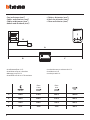
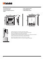
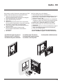
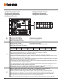
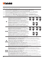
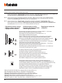
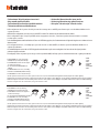
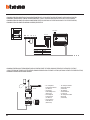
• Cavi e distanze (mm
2
)
• Cables and distances (mm
2
)
• Câbles et distances (mm
2
)
• Kabeln und Abstände (mm
2
)
• Cables y distancias (mm
2
)
• Kabels en afstanden (mm
2
)
• Cabos e distâncias (mm
2
)
B C
A
D
346040
PRI 110 - 240 V 50 - 60 Hz 370 mA - 225 mA
BUS 26.0 V 600 mA
BUS
PRI
PRI
BUS
0,28 mm
2
BTicino
336904
0,5 mm
2
BTicino
L4669
0,35 mm
2
1 mm
2
A 380 m 610 m 400 m 1000 m
B 200 m 290 m 210 m 580 m
C 180 m 320 m 190 m 560 m
D 30 m 50 m 30 m 100 m
• Installazione no a 3 PI
• Installation of up to 3 handsets
• Montage jusqu’à 3 PI
• Installation von bis zu 3 Türstationen
• Instalación con un máximo de 3 PI
• Installatie tot 3 PI
• Instalação até 3 UI

Audio - Kit
5
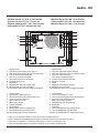
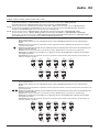
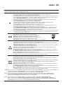
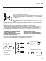
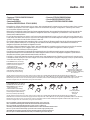
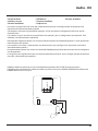
• A Pulsante locale apertura serratura.
B Chiamata al piano.
S+ S- 18 V; 4 A impulsivi. 250 mA mantenimento (30 Ω max).
• A Door lock release local pushbutton.
B Floor call.
S+ S- 18 V; 4 A impulsive. 250 mA holding current (30 max).
• A Bouton local ouverture serrure.
B Appel à l’étage.
S+ S- 18 V; 4 A impulsifs. 250 mA entretien (30 Ω max).
• A Lokale Schlossöffnungstaste.
B Etagenruf.
S+ S- 18 V; 4 A impulsstrom. 250 mA Haltestrom (30 max).
• A Pulsador local apertura cerradura.
B Llamada al piso.
S+ S- 18 V; 4 A por impulsos. 250 mA mantenimiento (30 Ω max).
• A Lokale knop opening slot.
B Oproep aan verdieping.
S+ S- 18 V; 4 A impulsief; 250 mA onderhoud (30 max).
• A Botão local de abertura da fechadura.
B Chamada ao piso.
S+ S- 18 V; 4 A instantâneos. 250 mA continuos (30 Ω max).
•
Schema monofamiliare
•
One-family diagram
•
Schéma mono-familial
•
Schema Einfamilienhaus
•
Esquema monofamiliar
•
Schema eensgezins
•
Esquema monofamiliar
N
= –
= –
S = –
T = –
M = –
J1 = –
J2
J1
= JMP
P
= –
–
=
=
JMP
230 Vac
A
BUS 2 1 PL S+ S-
P
= –
= –
= –
M
N
= –
= –
=
= –
BUS
B
5M 1
346040
PRI 110 - 240 V 50 - 60 Hz 370 mA - 225 mA
BUS 26.0 V 600 mA
BUS
PRI
PRI
BUS
OFF ON

6
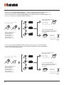
• Dati dimensionali
• Dimensional data
• Données dimensionnelles
• Maße
• Datos dimensionales
• Formaatgegevens
• Dados dimensionais
• Altezza consigliata salvo diversa normativa vigente.
• Recommended height, unless different regulations are specified.
• Hauteur conseillée sauf autre norme en vigueur.
• Empfohlene Höhe falls die gesetzlichen Vorschriften nichts anderes vorschreiben.
• Altura recomendada salvo normativa vigente diferente.
• Aanbevolen hoogte behoudens andere normen in voege.
• Altura aconselhada a não ser se a norma em vigor for diferente.
160 -165 cm
90 -130 cm
102 mm
155 mm
19 mm
49 mm
138 mm
144 mm

Audio - Kit
7
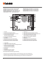
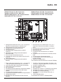
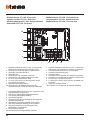
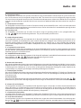
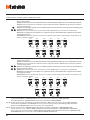
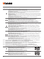
• Modulo fonico 351100 - Vista frontale
• Speaker module 351100 - Front view
• Module phonique 351100 - Vue frontale
• Audiomodul 351100 - Ansicht von vorn
• Módulo fónico 351100 - Vista frontal
• Geluidsmodule 351100 - Vooraanzicht
• Módulo fônico 351100 - Vista frontal
1. Altoparlante
2. LED verde indicazione porta aperta
3. LED verde indicazione comunicazione attiva
4. LED verde chiamata inoltrata
LED rosso sistema occupato
5. Sensore luminosità ambientale
6. Pulsanti di chiamata
7. Microfono
8. Regolazione volume altoparlante
9. Regolazione volume microfono
10. Connettore Mini USB per programmazione
1. Haut-parleur
2. LED vert indication porte ouverte
3. LED vert indication communication active
4. LED vert appel transmis
LED rouge système occupé
5. Capteur luminosité ambiante
6. Boutons d’appel
7. Micro
8. Réglage volume haut-parleur
9. Réglage volume micro
10. Connecteur Mini USB de programmation
1. Loudspeaker
2. Door open notication LED
3. Communication active notication LED
4. Green call forwarded LED
Red system busy LED
5. Room light sensor
6. Call pushbuttons
7. Microphone
8. Loudspeaker volume adjustment
9. Microphone volume adjustment
10. Mini-USB programming connector
1. Lautsprecher
2. Grüne LED Anzeige Tür auf
3. Grüne LED Anzeige Kommunikation aktiv
4. Grüne LED Ruf weitergeleitet
Rote LED System besetzt
5. Helligkeitssensor Umgebung
6. Ruftasten
7. Mikrofon
8. Lautstärkeregulierung Lautsprecher
9. Lautstärkeregulierung Mikrofon
10. Mini USB Verbinder für Programmierung
6
9
8
1
7
2
3
4
5
10*
6
• (*) Nota: per la programmazione tramite software TiSferaDesign vai su www.bticino.com
• (*) Note: To complete the programming procedure using the TiSferaDesign software visit the www.bticino.com website
• (*) Note: Pour la programmation à l’aide du logiciel TiSferaDesign, consulter le site www.bticino.com
• (*) Hinweis: Zur Programmierung über die software TiSferaDesign, sieh unsere Website www.bticino.com

8
1. Altavoz
2. LED verde señal puerta abierta
3. LED verde señal comunicación activada
4. LED verde llamada enviada
LED rojo sistema ocupado
5. Sensor de luminosidad ambiental
6. Pulsadores de llamada
7. Micrófono
8. Regulación del volumen del altavoz
9. Regulación del volumen del micrófono
10. Conector Mini USB para programación
1. Altifalante
2. LED verde de indicação de porta aberta
3. LED verde de indicação de comunicação activa
4. LED verde de chamada transmitida
LED vermelho de sistema ocupado
5. Sensor de luminosidade ambiental
6. Botões de chamada
7. Microfone
8. Regulação do volume do altifalante
9. Regulação do volume do microfone
10. Conector Mini USB para programação
1. Luidspreker
2. Groene LED indicatie deur open
3. Groene LED indicatie communicatie geactiveerd
4. LED verde chiamata inoltrata
LED rosso sistema occupato
5. Lichtsterktesensor omgeving
6. Beltoetsen
7. Microfoon
8. Volume luidspreker afstellen
9. Volume microfoon afstellen
10. Connector Mini USB voor programmering
6
9
8
1
7
2
3
4
5
10*
6
• (* )Nota: Para conocer la programación mediante el software TiSferaDesign, consulte el sitio www.bticino.com
• (*) Opmerking: Raadpleeg de website www.bticino.com voor de programmering met de software TiSferaDesign
• (*) Nota: Para a programação mediante software TiSferaDesign, roga-se consultar o sítio: www.bticino.com
• Modulo fonico 351100 - Vista frontale
• Speaker module 351100 - Front view
• Module phonique 351100 - Vue frontale
• Audiomodul 351100 - Ansicht von vorn
• Módulo fónico 351100 - Vista frontal
• Geluidsmodule 351100 - Vooraanzicht
• Módulo fônico 351100 - Vista frontal

Audio - Kit
9
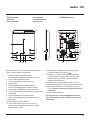
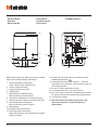
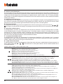
• Modulo fonico 351100 - Vista retro
• Speaker module 351100 - Back view
• Module phonique 351100 - Vue postérieure
• Audiomodul 351100 - Rückseite
• Módulo fónico 351100 - Vista posterior
• Geluidsmodule 351100 - Achteraanzicht
• Módulo fônico 351100 - Vista traseira
7
5
8
6
9
10
34 12
1. Collegamento elettroserratura (18 V; 4 A impulsivi
250 mA di mantenimento su 30 Ohm max)
2. Collegamento pulsante apriporta locale
3. Collegamento alimentazione locale
4. Collegamento Bus
5. Connettore per il collegamento ai moduli
successivi
6. Connettore per il collegamento del modulo
telecamera N&D
7. J2 estrarre per alimentazione locale
8. J1 estrarre per attivare due colonne di pulsanti di
chiamata
9. Sede conguratori
10. Connettore per il collegamento del modulo
teleloop
1. Branchement serrure électrique (18 V; 4 A à
impulsions 250 mA de maintien sur 30 Ohm
max.)
2. Branchement bouton d’ouverture porte local
3. Branchement alimentation locale
4. Branchement Bus
5. Connecteur de branchement aux modules
suivants
6. Connecteur de branchement du module caméra
N&D
7. J2 extraire pour alimentation locale
8. J1 extraire pour activer deux colonnes de
boutons d’appel
9. Logement congurateurs
10. Connecteur de branchement du module Teleloop
1. Anschluss und Steuerung elektr. Türschloss (18 V
4 A Impuls - 250 mA Haltestrom bei 30 Ohm max)
2. Anschluss Türöner lokal
3. Anschluss lokale Speisung
4. BUS - Anschluss
5. Verbinder für Anschluss an weitere Tastenmodule
6. Verbinder für Anschluss Kameramodul N&D
7. J2 entfernen für lokale Speisung
8. J1 entfernen, um zwei Spalten Ruftasten zu
aktivieren
9. Sitz für Konguratoren
10. Verbinder für Anschluss Teleloop-Modul
1. Electric door lock connection (18 V – 4 A impulsive
– 250 mA maintenance on 30 Ohm maximum)
2. Local door lock release pushbutton connection
3. Local power supply connection
4. BUS connection
5. Connector for the connection to subsequent modules
6. Connector for the connection of the N&D camera
module
7. J2 remove for local power supply
8. J1 remove to activate two columns of call pushbuttons
9. Congurator socket
10. Connector for the connection of the inductive
teleloop

10
7
5
8
6
9
10
34 12
1. Conexión electrocerradura (18 V; 4 A impulsivos
250 mA de mantenimiento a 30 Ohm máx.)
2. Conexión pulsador de apertura puerta local
3. Conexión alimentación local
4. Conexión BUS
5. Conector para los módulos sucesivos
6. Conector para el módulo telecámara N&D
7. J2: sacar para alimentación local
8. J1: sacar para activar las dos columnas de los
pulsadores de llamada
9. Alojamiento conguradores
10. Conector para el módulo del sistema de
amplicación por bucle de inducción (teleloop)
1. Conexão fechadura eléctrica (18 V; 4 A impulsivos
250 mA de mantimento em 30 Ohm ao máximo)
2. Conexão botão de abertura da porta local
3. Conexão alimentação local
4. Conexão ao Bus
5. Conector para a conexão aos módulos seguintes
6. Conector para a conexão do módulo câmara N&D
7. J2 extrair para alimentação local
8. J1 extrair para activar duas colunas de botões de
chamada
9. Sede dos conguradores
10. Conector para a conexão do módulo teleloop
1. Aansluiting elektrisch slot (18 V; 4 A impulsen 250
mA behoud op 30 Ohm max)
2. Aansluiting plaatselijke knop openen deur
3. Aansluiting plaatselijke voeding
4. Aansluiting met Bus
5. Connector voor de aansluiting op de volgende
modules met toetsen
6. Connector aansluiting module camera N&D
7. Voor de plaatselijke voeding J2 verwijderen
8. Voor de activering van de twee rijen met
beltoetsen J1 verwijderen
9. Plaats conguratoren
10. Connector aansluiting teleloop module
• Modulo fonico 351100 - Vista retro
• Speaker module 351100 - Back view
• Module phonique 351100 - Vue postérieure
• Audiomodul 351100 - Rückseite
• Módulo fónico 351100 - Vista posterior
• Geluidsmodule 351100 - Achteraanzicht
• Módulo fônico 351100 - Vista traseira

Audio - Kit
11
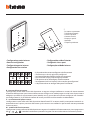
Alla pressione i tasti si illuminano ed emettono un
“beep” (disattivabile da procedura.)
1. Tasto attivazione comunicazione
LED verde lampeggiante: chiamata in arrivo
2. Tasto a soramento luci scale
3. Tasti a soramento programmabili *
4. Altoparlante
5. LED segnalazione esclusione suoneria
LED rosso lampeggiante: suoneria esclusa
6. Joystick per regolazioni e programmazioni
7. Tasto a soramento per attivazione posto estero /
ciclamento
8. Tasto disattivazione comunicazione
LED rosso lampeggiante: chiamata in corso
9. Microfono
10. Guide tattili per non vedenti
11. Tasto a soramento apertura serratura *
Led bianco lampeggiante: funzione "studio
professionale" attiva
12. Morsetti per il collegamento di un pulsante
esterno di chiamata al piano
13. Morsetti (1 - 5M) per collegamento suoneria
supplementare. Il collegamento deve essere
effettuato punto - punto sui morsetti della
suonerie supplementari
14. Morsetti per il collegamento al BUS SCS 2 fili
15. Microinterruttore ON / OFF di terminazione di tratta
16. Microinterruttore ON / OFF funzione “serratura
sicura”. Attivare la funzione con dispositivo non
alimentato
17. Sede dei configuratori
* Se alla pressione, i LED lampeggiano bianco, è
attiva la funzione "serratura sicura" ed il tasto è
disattivato.
• Posto interno
• Handset
• Poste interne
• Hausstation
• Unidad interior
• Intern punt
• Unidade interna
6
* 3
2
1
5
7
8
11*
4
9
10
Made in Italy
5M 1BUS
P
M
N
BTICINO
V.le Borri, 231
21100 (VA) ITALY
ON
CTS
1
2
OFF
OFF
ON
ON
17
16
15
12
13
14

12
When pressed, the keys light up and emit a “beep”
(that can be deactivated by procedure)
1. Communication enabling key
Green LED ashing: incoming call
2. Staircase light touch key
3. Programmable touch keys *
4. Loudspeaker
5. Bell exclusion notication LED
Red LED ashing: bell excluded
6. Joystick for adjustments and programming
7. Entrance panel/scrolling activation touch key
8. Communication disabling key
Red LED ashing: call in progress
9. Microphone
10. Tactile guides for the blinds
11. Door lock release touch key *
White LED ashing: active Professional Studio
(Oce) function
12. Clamps for the connection of an external call to
the oor pushbutton
13. Additional bell connection clamps (1 - 5M). The
connection must be point - point on the clamps of
the additional bells
14. 2 wires SCS BUS connection clamps.
15. Line termination ON / OFF micro-switch.
16. ON / OFF micro-switch for “safe door lock” function
To activate the function with device not powered
17. Congurator socket
* If the LEDs flash white when pressed, the “safe
door lock” function is active and the key is
deactivated.
• Posto interno
• Handset
• Poste interne
• Hausstation
• Unidad interior
• Intern punt
• Unidade interna
6
* 3
2
1
5
7
8
11*
4
9
10
Made in Italy
5M 1BUS
P
M
N
BTICINO
V.le Borri, 231
21100 (VA) ITALY
ON
CTS
1
2
OFF
OFF
ON
ON
17
16
15
12
13
14

Audio - Kit
13
À la pression, les touches s’illuminent et émettent un
«bip» (désactivable à travers la procédure prévue à
cet eet)
1. Touche activation communication
Voyant vert clignotant : arrivée d’un appel
2. Touche à eeurement lumières escaliers
3. Touche à eeurement programmables (*)
4. Haut-parleur
5. Voyant de signal exclusion sonnerie
Voyant rouge clignotant : sonnerie exclue
6. Joystick pour réglages et programmations
7. Touche à eeurement d’activation poste
externe/cyclage
8. Touche désactivation communication
Voyant rouge clignotant : appel en cours
9. Micro
10. Guides tactiles pour non-voyants
11. Touche à eeurement d’ouverture serrure (*)
Voyant blanc clignotant: fonction «bureau» active
12. Bornes de branchement d’un bouton externe
d’appel à l’étage
13. Bornes (1 - 5M) de branchement sonnerie
supplémentaire. Le branchement doit être
eectué point - point sur les bornes des sonneries
supplémentaires
14. Bornes de branchement au BUS SCS 2 ls
15. Microinterrupteur ON / OFF de n de ligne
16. Microinterrupteur ON/OFF fonction «serrure
sécurisée»
Activer la fonction avec le dispositif non alimenté
17. Logement des congurateurs
(*) Si, à la pression, les voyants clignotent sur le
blanc, la fonction «serrure sécurisée» est active et
la touche est désactivée.
Bei Betätigung leuchten die Tasten auf und geben
einen „Piepton“ ab (kann durch eine Prozedur
deaktiviert werden.)
1. Taste zur Aktivierung der Kommunikation
Grüne LED blinkt: eintreen eines Anrufs
2. Berührungstaste Treppenlicht
3. Programmierbare Berührungstasten
4. Lautsprecher
5. LED- Meldung Läutwerk ausgeschlossen
Rote LED blinkt: Läutwerk ausgeschlossen
6. Joystick für Regelung und Programmierung
7. Berührungstaste zum Aktivieren der Türstation
und Taktieren
8. Taste zur Deaktivierung der Kommunikation
Rote LED blinkt: Anruf im Gang
9. Mikrophon
10. Taktile Hilfe für Sehbehinderte
11. Berührungstaste Schlossöner*
Weiße Led blinkt: Funktion „Büro“ aktiv
12. Klemmen zum Anschluss an eine externe
Etagenruftaste
13. Klemmen (1 - 5M) zum Anschluss an ein
zusätzliches Läutwerk. Der Anschluss muss Punkt
zu Punkt an den Klemmen der zusätzlichen
Läutwerke erfolgen
14. Klemmen zum Anschluss an BUS, SCS, 2-Draht
15. Mikroschalter ON / OFF am Ende der Strecke.
16. Mikroschalter ON / OFF für die Funktion
„Schloss-Sicherheit“. Die Funktion mit stromloser
Vorrichtung aktivieren
17. Sitz der Konguratoren
* Wenn die LEDs beim Drücken weiß blinken, ist die
Funktion „Schloss-Sicherheit“ aktiv und die Taste
ist deaktiviert.ed il tasto è disattivato.
Con la presión, los botones se iluminan y emiten un
“beep” (desactivable según el procedimiento.)
1. Botón activación comunicación
LED verde parpadeante: llamada entrante
2. Botón de membrana luces escaleras
3. Botones de membrana programables *
4. Altavoz
5. LED de señalización de exclusión timbre
LED rojo parpadeante: timbre excluido
6. Joystick para regulaciones y programaciones
7. Botón de membrana para activación placa de
exterior / vista cíclica
8. Botón desactivación comunicación
LED rojo parpadeante: llamada corriente
9. Micrófono
10. Guías táctiles para invidentes
11. Botón de membrana apertura cerradura*
LED blanco parpadeante: función “Estudio
profesional” activa
12. Bornes para la conexión de un pulsador externo
de llamada a la planta
13. Bornes (1 - 5M) para la conexión de un timbre
adicional. Se ha de efectuar la conexión punto -
punto en los bornes de los timbres adicionales
14. Bornes para la conexión al BUS SCS 2 hilos
15. Microinterruptor ON / OFF nal de tramo.
16. Microinterruptor ON / OFF función “cerradura segura”.
Activar la función con dispositivo no alimentado
17. Alojamiento de los conguradores.
* Si con la presión, los LEDs parpadean en color
blanco, se activa la función “cerradura segura” y el
botón se desactiva. ed il tasto è disattivato.

14
• Posto interno
• Handset
• Poste interne
• Hausstation
• Unidad interior
• Intern punt
• Unidade interna
6
* 3
2
1
5
7
8
11*
4
9
10
Made in Italy
5M 1BUS
P
M
N
BTICINO
V.le Borri, 231
21100 (VA) ITALY
ON
CTS
1
2
OFF
OFF
ON
ON
17
16
15
12
13
14
De toetsen gaan branden en laten een “piep” (kan
met de procedure gedeactiveerd worden) horen
wanneer erop gedrukt wordt.
1. Toets activering communicatie
Groen led knippert: binnenkomende oproep
2. Touch-toets traphuisverlichting
3. Programmeerbare touch-toetsen*
4. Luidspreker
5. Led melding uitsluiting beltoon
Rode led knippert : beltoon uitgesloten
6. Joystick voor regelingen en programmeringen
7. Touch-toets voor activering buitenpost/cyclische
weergave
8. Toets deactivering communicatie
Rode led knippert : lopende oproep
9. Microfoon
10. Tastgeleiders voor blinden
11. Touch-toetsen slotontgrendeling*
Witte led knippert: functie “professionele studio”
geactiveerd
12. Aansluitklemmen voor de verbinding van een
externe knop op de verdieping
13. Aansluitklemmen (1 - 5M) voor de verbinding
van een extra beltoon. Verricht een punt - punt
verbinding op de aansluitklemmen van de extra
beltonen
14. Aansluitklemmen voor de verbinding met de SCS
2-Draads BUS
15. Microschakelaar ON / OFF voor de afsluiting van
het traject
16. Microschakelaar ON / OFF functie “veilig slot”.
Activeer de functie wanneer het apparaat niet
wordt gevoed
17. Plaats van de conguratoren
* De functie “veilig slot” is geactiveerd en de toets
is gedeactiveerd als de witte leds knipperen
wanneer op de toets gedrukt wordt.

Audio - Kit
15
Ao carregar as teclas iluminam-se e emitem um “bip”
(pode ser desativado através de procedimento.)
1. Tecla de ativação de comunicação
LED verde intermitente: chamada em chegada
2. Tecla de toque luzes das escadas
3. Teclas de toque programáveis *
4. Altifalante
5. LED de sinalização de exclusão da campainha
LED vermelho intermitente: campainha excluída
6. Joystick para regulações e programações
7. Tecla de toque para ativação unidade externa /
ativação cíclica
8. Tecla de desactivado de comunicação
LED vermelho intermitente: chamada em
andamento
9. Microfone
10. Guias táteis para não videntes
11. Tecla de toque abertura da fechadura *
Led branco a piscar: função “estúdio prossional” ativa
12. Bornes para a conexão de um botão externo de
chamada no piso
13. Bornes (1 - 5M) para a conexão de uma campainha
adicional. É necessário realizar uma conexão ponto-
a-ponto nos bornes das campainhas adicionais
14. Bornes para a conexão ao BUS SCS DE 2 os.
15. Micro-interruptor ON / OFF de terminação do
segmento.
16. Microinterruptor ON / OFF função “fechadura segura”.
Ativar a função com dispositivo não alimentado
17. Sede dos conguradores
* Se ao carregar, os LED piscam em branco, está
ativa a "fechadura segura" e a tecla é desativada.
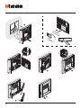
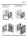
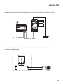
• Installazione posto esterno
• Entrance panel installation
•
Installation du poste extérieur
• Installation der Türstation
•
Instalación de la placa exterior
• Installatie externe plaats
•
Instalação da unidade externa
1
2
3

16
8
9
5
6
7
4
1
2

Audio - Kit
17
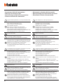
• Se si manifestasse il disturbo del fischio, (effetto Larsen), ridurre prima la potenza del microfono , agendo
con un cacciavite sul potenziometro corrispondente, fino ad un livello accettabile. Qualora il fenomeno persi-
sta, agire sul potenziometro dell’altoparlante in modo da eliminare l’inconveniente. Se il volume è troppo
basso, aumentare prima il volume dell’altoparlante ed eventualmente anche quello del microfono, tenendo
presente che è preferibile una trasmissione chiara e priva di disturbi, che una al limite dell’innesco (Larsen).
• In case of a whistle (Larsen effect), first reduce the microphones
power, adjusting the corresponding potentiom-
eters with a screw driver, until an acceptable level is reached. Should the whistle persist, adjust the loudspeakers
volume in order to eliminate the trouble. If the volume is too low level then, increase first the potentiometer of the
loudspeaker and secondly the one for the microphone, bearing in mind that a clear and noise free reception is prefer-
able than one just before whistling (Larsen).
• Lors de sifflement (effet de Larsen), reduire d’abord la puissance du micro
sur le potentiomètre correspon-
dant, à l’aide d’un tournevis, jusqu’à l’obtention d’un niveau satisfaisant. Si le sifflement persiste, régler le po-
tentiomètre du hautparleur jusqu’à l’élimination de celui-ci. Si le volume est trop bas, augmenter d’abord
la puissance du haut-parleur et éventuellement celle du micro, en considérant qu’une réception claire et sans
parasite est préférable à une communication à la limite de l’accrochage (effet de Larsen).
• Beim etwaigen Auftreten eines Pfeiftones (Larsen-Effekt), zuerst die Lautstärke des Mikrophones
bis auf einen
annehmbaren Wert herabsetzen, indem man das entsprechende Potentiometer mit einem Schraubendreher einstellt.
Sollte die Störung weiterhin bestehen, dann das Potentiometer des Lautsprechers bis zur Beseitigung des Pfeifto-
nes einstellen. Ist die Lautstärke nun zu niedrig, dann zuerst die des Lautsprechers und erst danach evtl. auch die des
Mikrophones erhohen, wobei ein deutlicher und störungsfreier Empfang einem an der Störungsgrenze liegendem
(Larsen-Effekt) vorzuziehen ist.
• Si se manifesta el silbido de acoplamiento, (efecto Larsen), reducir primero la potencia del micrófono
, girando
con un destornillador el potenciómetro correspondiente, hasta obtener un nivel aceptable. Si el fenómeno per-
sistiera, regular el potenciómetro del altavoz hasta eliminar la interferencia. Si el volumen es demasiado bajo,
aumentar primero el volumen del altavoz y eventualmente también el del micrófono, teniendo en cuenta que es
preferible una transmissión clara y limpia de interferencias, que una al limite del acoplo (Larsen).
• Als er een fluittoon hoorbaar is (effect van Larsen): verminder eerst het vermogen van de microfoon
met behulp
van een schroevendraaier zijn stroomregelaar zo te regelen dat de geluidssterkte van het gefluit aanvaardbaar is. Als
het verschijnsel niet verdwijnt, dan moet u ook de stroomregelaar van de luidspreker bijstellen. Als de geluidssterk-
te nu te klein is, verhoog dan eerst de geluidssterkte van de luidspreker en daarna eventueel ook die van de microfoon,
en denk er bij het bijstellen aan dat een duidelijk hoorbaar en ongestoord geluid beter is dan een harder geluid op de
grens van het Larsen effect.
• Se se manifestar uma interferência no som (efeito de Larsen), começar por diminuir a potência do microfone
, rodando o potenciómetro correspondente com uma chave de parafusos, até obter um nível aceitável. Se
o fenómeno persistir, regular o potenciómetro do altifalante de modo a eliminar o problema. Se o volume
estiver demasiado baixo, começar por aumentar o volume do altifalante e depois, se necessário, o do microfo-
ne, tendo presente que é melhor ter uma transmissão clara e sem interferências, que uma no limiar de início
de efeitos Larsen.

18
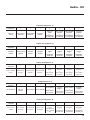
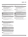
• Configurazione posto esterno
• Entrance panel configuration
• Configuration poste extérieur
• Konfiguration Türstation
• Configuración placa exterior
• Configuratie externe plaats
•
Configuração unidade externa
P N M J1S T J2
P
N
S
- Possono non essere configurati
- They do not need to be configured
- Ils peuvent ne pas être configurés
- Brauchen nicht konfiguriert zu werden
- Pueden no precisar configuración
- Kunnen niet worden geconfigureerd
- Podem não serconfigurados
T
- Temporizzatore serratura (vedi tabella)
- Door lock timer relay (see table)
- Temporisation serrure (voir tableau)
- Zeitgeber schlossrelaiscerradura (siehe Tabelle)
- Temporizador relé cerradura (véase la tabla)
- Timer deurslotrelais (zie de tabel)
- Temporizador do relé da fechadura (veja a tabela)
– 1 2 3 4 5 6 7
4 s 1 s 2 s 3 s
*
6 s 8 s 10 s
* Funzionamento come pulsante per max. 10 sec. dopodichè entra in stand-by.
Per estendere tale funzionamento oltre i 10 sec. utilizzare l’attuatore 346210 configurato con MOD=5.
* Operation as pushbutton for 10 sec. max after which it goes in stand-by.
In order to extend this type of operation over 10 seconds, use the actuator, item 346210 configured with MOD=5.
* Fonctionnement comme bouton pendant 10 sec. max., ensuite passe en stand-by. Pour étendre ce fonctionnement au-delà de 10
sec., utiliser l’actionneur 346210 configuré sur MOD=5.
* Die Tastenfunktion dauert max. 10 sec.; danach schaltet sie auf Standby. Um diese Funktion zu verlängern und mehr als 10 sec. dauern
zu lassen, den Aktor 346210 verwenden und mit MOD=5 konfigurieren.
* Funcionamiento como pulsador durante al máx.10 s. después se pone en standby. Para ampliar dicho funcionamiento a más de 10
s., use el actuador art. 346210 configurado con MOD = 5.
* 10 sec. lange werking als knop, vervolgens vindt de overschakeling naar stand-by plaats. Laat deze functie langer dan 10 sec. duren
met behulp van de actuator 346210 die als MOD=5 is geconfigureerd.
* Funcionamento como botão por um máximo de 10 segundos, depois disto dispõe-se em standby. Para prolongar este
funcionamento por mais de 10 segundos, utilizar o atuador 346210 configurado com MOD=5.s
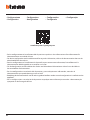
M
- Attivazione / disattivazione toni di chiamata, apertura serratura e gestione illuminazione notturna sempre ON.
- Enabling / disabling of call sounds, door lock release sounds, and setting of night lighting always ON.
- Activation / désactivation tonalités d’appel, tonalités d’ouverture serrure et gestion éclairage nocturne toujours ON.
- Aktivieren/deaktivieren der Ruftöne, des Schlosstons beim Öffnen und Verwaltung der nächtlichen Beleuchtung immer auf ON.
- Activa/desactiva los tonos de llamada, tonos de apertura de la cerradura y gestiona la iluminación nocturna siempre ON.
- Activering / deactivering tonen oproep, tonen openen slot en beheer nachtverlichting altijd ON.
- Activação / desactivação dos tons de chamada, dos tons de abertura do trinco e gestão da iluminação nocturna sempre ON.

Audio - Kit
19
Numero del configuratore - M
0 = nessun
configuratore
1 2 3 4 5 6 7
Tutti i toni
attivati
Tono serratura
disattivato
Tono di chiamata
disattivato
Tutti i toni
disattivati
Tutti i toni
attivati
+
retroilluminazio-
ne sempre ON
Tono serratura
disattivato
+
retroilluminazio-
ne sempre ON
Tono di chiamata
disattivato
+
retroilluminazio-
ne sempre ON
Tutti i toni
disattivati
+
retroilluminazio-
ne sempre ON
Number of the configurator - M
0 = no
configurator
1 2 3 4 5 6 7
All sounds
enabled
Door lock sound
disabled
Call sound
disabled
All sounds
disabled
All sounds
enabled
+
backlighting
always ON
Door lock sound
disabled
+
backlighting
always ON
Call sound
disabled
+
backlighting
always ON
All sounds
disabled
+
backlighting
always ON
Numéro du configurateur - M
0 = aucun
congurateur
1 2 3 4 5 6 7
Toutes les tonalités
activées
Tonalité serrure
désactivée
Tonalité d’appel
désactivée
Toutes les tonalités
désactivées
Toutes les tonalités
activées
+
rétro-éclairage
toujours ON.
Tonalité serrure
désactivée
+
rétro-éclairage
toujours ON.
Tonalité d’appel
désactivée
+
rétro-éclairage
toujours ON.
Toutes les tonalités
désactivées
+
rétro-éclairage
toujours ON.
Konfiguratornummer - M
= kein
Kongurator
1 2 3 4 5 6 7
Alle Töne aktiviert
Schlosston
deaktiviert
Rufton deaktiviert Alle Töne deaktiviert
Alle Töne aktiviert
+
Rückbeleuchtung
immer auf ON
Schlosston
deaktiviert
+
Rückbeleuchtung
immer auf ON
Rufton deaktiviert
+
Rückbeleuchtung
immer auf ON
Alle Ruftöne
deaktiviert
+
Rückbeleuchtung
immer auf ON
Numero del configurador - M
0 = ningun
congurador
1 2 3 4 5 6 7
Todos los tonos
activados
Tono cerradura
desactivado
Tono de llamada
desactivado
Todos los tonos
desactivados
Todos los tonos
activados
+ retroiluminación
siempre encendida
(ON)
Tono cerradura
desactivado
+
retroiluminación
encendida (ON)
Tono de llamada
desactivado
+
retroiluminación
encendida (ON)
Todos los tonos
desactivados
+
retroiluminación
encendida (ON)

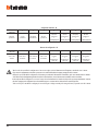
20
- Tutte le volte che si modifica la configurazione è necessario togliere e ridare l’alimentazione all’impianto, attendendo circa 1 minuto.
- Every time the configuration is altered the system must be switched off and back on again, waiting for about 1 minute.
- Chaque fois que l’on modifie la configuration, il faut retirer, puis redonner l’alimentation à l’installation, après avoir attendu environ 1 minute.
- Jedes Mal, wenn die Konfiguration geändert wird, den Strom abschalten, etwa 1 Minute warten und dann wieder einschalten.
- Cada vez que modifica la configuración, es necesario cortar y volver a dar alimentación a la instalación, después de esperar aproximadamente 1 minuto.
- Na iedere wijziging in de configuratie moet de installatie ongeveer 1 minuut van het elektriciteitsnet worden afgesloten.
- Todas as vezes que se modificar a configuração é necessário ligar e desligar a instalação da energia eléctrica, esperando cerca de 1 minuto.
Configurator nummerr - M
0 = geen
congurator
1 2 3 4 5 6 7
Alle tonen
geactiveerd
Toon slot
gedeactiveerd
Toon oproep
gedeactiveerd
Alle tonen
gedeactiveerd
Alle tonen
geactiveerd
+
verlichting altijd ON
Toon slot
gedeactiveerd
+
verlichting altijd ON
Toon oproep
gedeactiveerd
+
verlichting altijd ON
Alle tonen
geactiveerd
+
verlichting altijd ON
Numero do configurador - M
0 = nenhum
configurador
1 2 3 4 5 6 7
Todos os tons
activados
Tom do trinco
desactivado
Tom de chamada
desactivado
Todos os tons
desactivados
Todos os tons
activados
+
retroiluminação
sempre ON
Tom do trinco
desactivado
+
retroiluminação
sempre ON
Tom de chamada
desactivado
+
retroiluminação
sempre ON
Todos os tons
desactivados
+
retroiluminação
sempre ON
La pagina si sta caricando...
La pagina si sta caricando...
La pagina si sta caricando...
La pagina si sta caricando...
La pagina si sta caricando...
La pagina si sta caricando...
La pagina si sta caricando...
La pagina si sta caricando...
La pagina si sta caricando...
La pagina si sta caricando...
La pagina si sta caricando...
La pagina si sta caricando...
La pagina si sta caricando...
La pagina si sta caricando...
La pagina si sta caricando...
La pagina si sta caricando...
La pagina si sta caricando...
La pagina si sta caricando...
La pagina si sta caricando...
La pagina si sta caricando...
La pagina si sta caricando...
La pagina si sta caricando...
La pagina si sta caricando...
La pagina si sta caricando...
La pagina si sta caricando...
La pagina si sta caricando...
La pagina si sta caricando...
La pagina si sta caricando...
La pagina si sta caricando...
La pagina si sta caricando...
La pagina si sta caricando...
La pagina si sta caricando...
-
 1
1
-
 2
2
-
 3
3
-
 4
4
-
 5
5
-
 6
6
-
 7
7
-
 8
8
-
 9
9
-
 10
10
-
 11
11
-
 12
12
-
 13
13
-
 14
14
-
 15
15
-
 16
16
-
 17
17
-
 18
18
-
 19
19
-
 20
20
-
 21
21
-
 22
22
-
 23
23
-
 24
24
-
 25
25
-
 26
26
-
 27
27
-
 28
28
-
 29
29
-
 30
30
-
 31
31
-
 32
32
-
 33
33
-
 34
34
-
 35
35
-
 36
36
-
 37
37
-
 38
38
-
 39
39
-
 40
40
-
 41
41
-
 42
42
-
 43
43
-
 44
44
-
 45
45
-
 46
46
-
 47
47
-
 48
48
-
 49
49
-
 50
50
-
 51
51
-
 52
52


in altre lingue
- English: Bticino 364234 Operating instructions
- français: Bticino 364234 Mode d'emploi
- español: Bticino 364234 Instrucciones de operación
- Deutsch: Bticino 364234 Bedienungsanleitung
- Nederlands: Bticino 364234 Handleiding
- português: Bticino 364234 Instruções de operação
Documenti correlati
-
Bticino 344625 Istruzioni per l'uso
-
-
-
-
-
-
Bticino 352500 Manuale utente
-
-
-
