
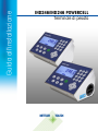
Installation Manual
IND246 and IND246 POWERCELL
Weighing Terminal


Service
IND246
and
IND246
POWERCELL Weighing Terminal
METTLER TOLEDO Service
Essential Services for Dependable Performance of Your IND246 and IND246 POWERCELL
Weighing Terminal
Congratulations on choosing the quality and precision of METTLER TOLEDO. Proper use of your
new equipment according to this Manual and regular calibration and maintenance by our factory-
trained service team ensures dependable and accurate operation, protecting your investment.
Contact us about a service agreement tailored to your needs and budget. Further information is
available at www.mt.com/service.
There are several important ways to ensure you maximize the performance of your investment:
1.
Register your product: We invite you to register your product at
www.mt.com/productregistration so we can contact you about enhancements, updates and
important notifications concerning your product.
2.
Contact METTLER TOLEDO for service: The value of a measurement is proportional to its
accuracy – an out of specification scale can diminish quality, reduce profits and increase
liability. Timely service from METTLER TOLEDO will ensure accuracy and optimize uptime and
equipment life.
a.
Installation, Configuration, Integration and Training: Our service representatives are factory-
trained, weighing equipment experts. We make certain that your weighing equipment is
ready for production in a cost effective and timely fashion and that personnel are trained for
success.
b.
Initial Calibration Documentation: The installation environment and application
requirements are unique for every industrial scale so performance must be tested and
certified. Our calibration services and certificates document accuracy to ensure production
quality and provide a quality system record of performance.
c.
Periodic Calibration Maintenance: A Calibration Service Agreement provides on-going
confidence in your weighing process and documentation of compliance with requirements.
We offer a variety of service plans that are scheduled to meet your needs and designed to
fit your budget.
d.
GWP® Verification: A risk-based approach for managing weighing equipment allows for
control and improvement of the entire measuring process, which ensures reproducible
product quality and minimizes process costs. GWP (Good Weighing Practice), the science-
based standard for efficient life-cycle management of weighing equipment, gives clear
answers about how to specify, calibrate and ensure accuracy of weighing equipment,
independent of make or brand.


© METTLER TOLEDO 2017
No part of this manual may be reproduced or transmitted in any form or by any
means, electronic or mechanical, including photocopying and recording, for any
purpose without the express written permission of METTLER TOLEDO.
U.S. Government Restricted Rights: This documentation is furnished with
Restricted Rights.
Copyright 2017 METTLER TOLEDO. This documentation contains proprietary
information of METTLER TOLEDO. It may not be copied in whole or in part
without the express written consent of METTLER TOLEDO.
METTLER TOLEDO reserves the right to make refinements or changes to the
product or manual without notice.
COPYRIGHT
METTLER TOLEDO
®
is a registered trademark of Mettler-Toledo, LLC. All other
brand or product names are trademarks or registered trademarks of their
respective companies.
METTLER TOLEDO RESERVES THE RIGHT TO MAKE REFINEMENTS OR
CHANGES WITHOUT NOTICE.
FCC Notice
This device complies with Part 15 of the FCC Rules and the Radio Interference
Requirements of the Canadian Department of Communications. Operation is
subject to the following conditions: (1) this device may not cause harmful
interference, and (2) this device must accept any interference received, including
interference that may cause undesired operation.
This equipment has been tested and found to comply with the limits for a Class
A digital device, pursuant to Part 15 of FCC Rules. These limits are designed to
provide reasonable protection against harmful interference when the equipment
is operated in a commercial environment. This equipment generates, uses, and
can radiate radio frequency energy and, if not installed and used in accordance
with the instruction manual, may cause harmful interference to radio
communications. Operation of this equipment in a residential area is likely to
cause harmful interference in which case the user will be required to correct the
interference at his or her expense.
Declaration of Conformity is available at
http://glo.mt.com/global/en/home/search/compliance.html/compliance/.

RoHS Compliance Statement.
The majority of our products fall within categories 8 and 9. Those categories
currently do not fall within the scope of the Directive 2002/95/EG (RoHS) of
January 27, 2003. If our products are intended for use in other products
which themselves fall within the scope of the RoHS Directive, compliance
requirements have to be separately negotiated contractually.
Those products which fall within categories 1-7 and 10 will be in compliance
with the EU RoHS Directive from no later than July 1, 2006.
If it is not possible for technical reasons to replace any non-RoHS-compliant
substances in any of the above products as required, we plan to inform our
customers in a timely manner
Statement regarding harmful substances
We do not make direct use of harmful materials such as asbestos, radioactive
substances or arsenic compounds. However, we purchase components from
third party suppliers, which may contain some of these substances in very small
quantities.
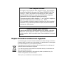
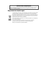
Disposal of Electrical and Electronic Equipment
In conformance with the European Directive 2002/96/EC on Waste Electrical and Electronic
Equipment (WEEE) this device may not be disposed of in domestic waste. This also applies
to countries outside the EU, per their specific requirements.
Please dispose of this product in accordance with local regulations at the collecting point
specified for electrical and electronic equipment.
If you have any questions, please contact the responsible authority or the distributor from
which you purchased this device.
Should this device be passed on to other parties (for private or professional use), the
content of this regulation must also be related.
Thank you for your contribution to environmental protection.

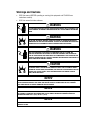
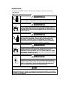
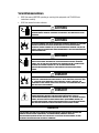
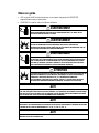
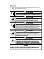
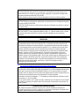
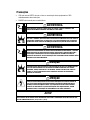
Warnings and Cautions
• READ this manual BEFORE operating or servicing this equipment and FOLLOW these
instructions carefully.
• SAVE this manual for future reference.
WARNING
FOR CONTINUED PROTECTION AGAINST SHOCK HAZARD CONNECT THE AC VERSION OF THE
IND246 TERMINAL TO PROPERLY GROUNDED OUTLET ONLY. DO NOT REMOVE THE GROUND
PRONG.
WARNING
DO NOT USE THE IND246 TERMINAL IN AREAS CLASSIFIED AS HAZARDOUS BECAUSE OF
COMBUSTIBLE OR EXPLOSIVE ATMOSPHERES. CONTACT AN AUTHORIZED METTLER TOLEDO
REPRESENTATIVE FOR INFORMATION ABOUT HAZARDOUS AREA APPLICATIONS.
WARNING
WHEN THIS EQUIPMENT IS INCLUDED AS A COMPONENT PART OF A SYSTEM, THE
RESULTING DESIGN MUST BE REVIEWED BY QUALIFIED PERSONNEL WHO ARE FAMILIAR
WITH THE CONSTRUCTION AND OPERATION OF ALL COMPONENTS IN THE SYSTEM AND THE
POTENTIAL HAZARDS INVOLVED. FAILURE TO OBSERVE THIS PRECAUTION COULD RESULT IN
BODILY HARM AND/OR PROPERTY DAMAGE.
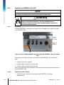
CAUTION
THE BATTERY USED IN THIS DEVICE MAY PRESENT A RISK OF FIRE OR CHEMICAL BURN IF
MISTREATED. DO NOT CRUSH, DISASSEMBLE, HEAT ABOVE 60°C OR INCINERATE. REPLACE
BATTERY WITH 72253419 ONLY. USE OF ANOTHER BATTERY MAY PRESENT A RISK OF
BURN, FIRE OR EXPLOSION.
NOTICE
NiMH BATTERIES SLOWLY DISCHARGE WHEN NOT USED (FOR EXAMPLE WHEN STORED FOR FUTURE USE).
BATTERY OPERATED TERMINALS AND SPARE NiMH BATTERY PACKS IN STORAGE MUST BE FULLY CHARGED
EVERY THREE MONTHS TO PREVENT PERMANENT BATTERY DAMAGE.
NOTICE
DO NOT ATTEMPT TO CHARGE THE BATTERY IF THE BATTERY TEMPERATURE IS BELOW 0°C (32°F). CHARGING IS
NOT POSSIBLE AT OR BELOW THIS TEMPERATURE. DO NOT OPERATE THE BATTERY CHARGER OUTSIDE ITS
TEMPERATURE RANGE OF 0°C (32°F) TO 40°C (104°F).
NOTICE
DISPOSE OF USED BATTERY PROMPTLY. KEEP AWAY FROM CHILDREN. DO NOT DISASSEMBLE AND DO NOT
DISPOSE OF IN FIRE.

Warnings and Cautions
NOTICE
OBSERVE PRECAUTIONS FOR HANDLING ELECTROSTATIC SENSITIVE DEVICES.

64084463 / Rev. 03 / 12/2017
METTLER TOLEDO IND246 and IND246 POWERCELL Weighing Terminal Installation Manual 1
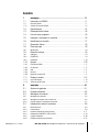
Contents
1 Introduction ...................................................................... 1-1
1.1. IND246 Overview ............................................................... 1-1
1.1.1. Standard Features .................................................................................. 1-1
1.1.2. IND246 Terminal Versions ...................................................................... 1-2
1.2. Specifications .................................................................... 1-2
1.3. Battery Performance ........................................................... 1-5
1.4. Use in Hazardous Areas ...................................................... 1-6
1.5. Inspection and Contents Checklist ........................................ 1-6
1.6. Model Identification ............................................................ 1-7
1.7. Physical Dimensions .......................................................... 1-8
1.8. Main PCB .......................................................................... 1-9
1.8.1. SD Memory ........................................................................................... 1-9
1.9. Scale Bases ...................................................................... 1-9
1.9.1. Analog .................................................................................................. 1-9
1.9.2. POWERCELL .......................................................................................... 1-9
1.9.3. PowerDeck .......................................................................................... 1-10
1.10. Options ........................................................................... 1-10
1.10.1. COM2 Serial Port .................................................................................. 1-10
1.10.2. Discrete I/O .......................................................................................... 1-11
1.10.3. USB .................................................................................................... 1-11
1.10.4. Ethernet ............................................................................................... 1-11
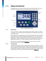
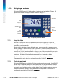
1.11. Display and Keyboard ...................................................... 1-12
1.11.1. Display Layout ..................................................................................... 1-12
1.11.2. Front Panel Keys .................................................................................. 1-12
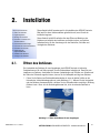
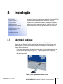
2 Installation ....................................................................... 2-1
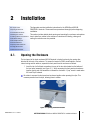
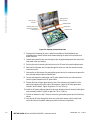
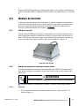
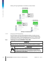
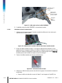
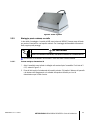
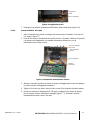
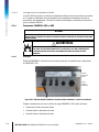
2.1. Opening the Enclosure ........................................................ 2-1
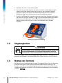
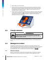
2.2. Environmental Protection ..................................................... 2-2
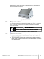
2.3. Mounting the Terminal ........................................................ 2-2
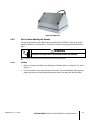
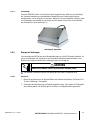
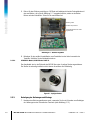
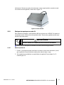
2.3.1. Desktop Mounting .................................................................................. 2-2
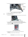
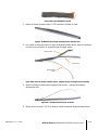
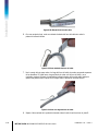
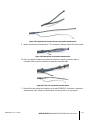
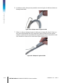
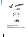
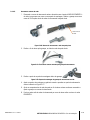
2.3.2. Wall or Column Mounting with Brackets ................................................... 2-3
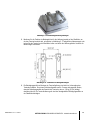
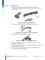
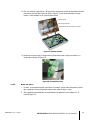
2.3.3. Attaching Brackets and Mounting Terminal ................................................ 2-9
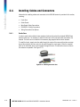
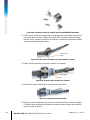
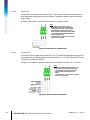
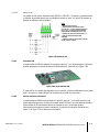
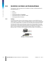
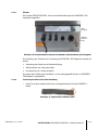
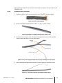
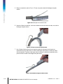
2.4. Installing Cables and Connectors ....................................... 2-10
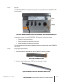
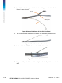
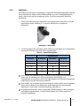
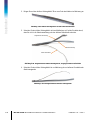
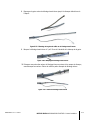
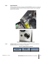
2.4.1. Ferrite Core .......................................................................................... 2-10
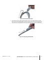
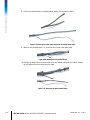
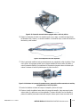
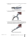
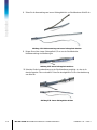
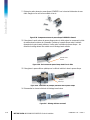
2.4.2. Cable Glands ....................................................................................... 2-11
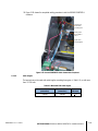
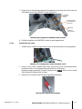
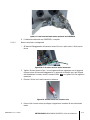
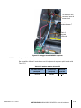
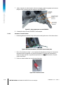
2.4.3. Main Board Wiring Connections ............................................................. 2-13
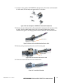
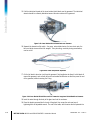
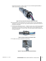
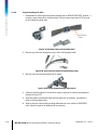
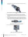
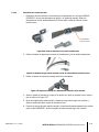
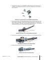
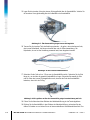
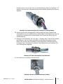
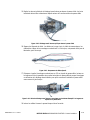
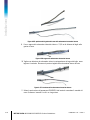
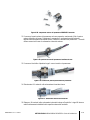
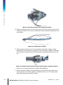
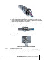
2.4.4. PDX or GDD POWERCELL Cabling ......................................................... 2-18
2.4.5. PowerDeck Connection ......................................................................... 2-30
2.4.6. Wiring Connections for Options .............................................................. 2-31

2 METTLER TOLEDO IND246 and IND246 POWERCELL Weighing Terminal Installation Manual
64084463 / Rev. 03 / 12/2017
Contents
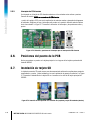
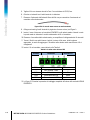
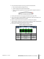
2.5. PCB Switch Settings .......................................................... 2-37
2.5.1. Main PCB Switches .............................................................................. 2-37
2.5.2. Discrete I/O Switch ............................................................................... 2-38
2.6. PCB Jumper Positions ...................................................... 2-39
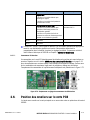
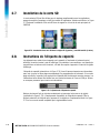
2.7. SD Card Installation .......................................................... 2-39
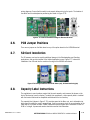
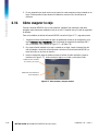
2.8. Capacity Label Instructions ................................................ 2-39
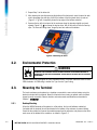
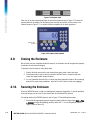
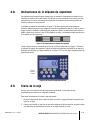
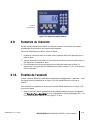
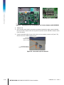
2.9. Closing the Enclosure ....................................................... 2-40
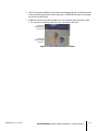
2.10. Securing the Enclosure ...................................................... 2-40

64084463 | 03 | 12/2017
METTLER TOLEDO IND246 and IND246 POWERCELL Installation Manual
1-1
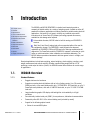
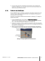
This chapter covers
• Overview
• Specifications
• Use in Hazardous Areas
• Safe Disposal Requirement
• Inspection and Contents
Checklist
• Model Identification
• Physical Dimensions
• Main PCB
• Scale Bases
• Options
• Display and Keyboard
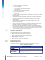
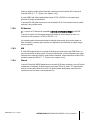
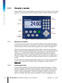
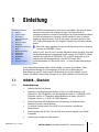
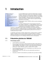
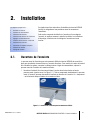
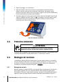
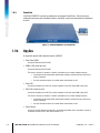
1 Introduction
The IND246 and IND246 POWERCELL industrial scale terminals provide a
compact yet flexible solution to a variety of weighing needs. Available as either AC
powered for stationary applications or battery-powered for portable analog load cell
applications, this terminal is at home in virtually any industrial environment.
Innovative use of Secure Data (SD) Memory technology expands the memory
available for data storage when required.
Unless stated otherwise, IND246 refers to both the analog and POWERCELL
versions.
Both 2mv/V and 3mv/V analog load cells are supported without the need for
any configuration change. The POWERCELL model supports the advanced
capabilities of POWERCELL PDX and GDD load cells, featuring sophisticated self-
diagnostics. The PowerDeck model for POWERCELL supports a connector for quick
home run cable termination, faster calibration and automatic addressing. The
IND246 delivers precision measurement data from grams to tons in a single, cost
effective package.
Standard applications include basic weighing, animal weighing, check weighing, counting, peak
weight measurement and vehicle weighing. Whether communicating weight data to a PC or
providing a serial output of data to a printer, the IND246 terminal offers solutions for a wide range
of applications.
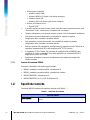
1.1. IND246 Overview
1.1.1. Standard Features
• Rugged stainless steel enclosure
• Supports one analog load cell platform with up to four (battery version), ten (AC version)
350Ω load cells; or one scale platform with up to 12 POWERCELL PDX load cells; or up to 3
PowerDeck scale platforms, each with 4 SLB615D load cells; or up to 12 SLC611D LCWM
load cells
• Large transflective graphic LCD display with backlight for vivid readability in all light
conditions
• One electrically isolated serial port (COM1) for asynchronous, bidirectional communication
• Powered by either 85–264 V AC or internal battery pack (selected by model)
• Support for the following option boards:
Choice of one serial/DIO option:

1-2
METTLER TOLEDO IND246 and IND246 POWERCELL Installation Manual
64084463 | 03 | 12/2017
Introduction
o COM2 Serial Interface
o COM2 and Discrete I/O interface (analog version only)
o USB Serial Interface
o USB and Discrete I/O interface (analog version only)
Optional network interface:
o Ethernet TCP/IP
• Front panel key access to basic weighing functions – zero, tare, clear, unit switching and
print
• Alpha numeric keypad for simple, quick entry of tare and identification information
• Selectable primary unit of measure including grams, kilograms, pounds, tons, metric tons
• Selectable second unit of measure including grams, kilograms, pounds, ounces, tons and
metric tons
• Backup and restore of configuration and calibration settings, using SD memory device or
InSite
®
SL PC tool (included)
• PC-based File Transfer Tool (included) exchanges application files and tables with the
IND246 terminal
• Automatic shutoff and backlight timeout features to help conserve energy on the battery
powered version
1.1.2. IND246 Terminal Versions
The terminal is available in the following four versions:
• IND246 Harsh enclosure, AC power
• IND246 Harsh enclosure, Battery power
• IND246 POWERCELL, AC power
• IND246 POWERCELL for SL_61xD, AC power
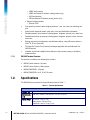
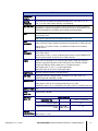
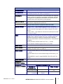
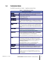
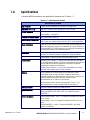
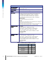
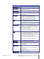
1.2. Specifications
The IND246 terminal conforms to the specifications listed in Table 1-1.
Table 1-1: Terminal Specifications
IND246 Specifications
Enclosure Type
Stainless steel, configurable as desk top or wall mount enclosure
Dimensions (w ×
h × d)
230 mm x 146 mm x 165 mm (9 in. x 5.75 in. x 6.5 in.)
Shipping Weight
AC Version: 3.4 kg (7.5 lb)
Battery Version: 3.9 kg (8.5 lb)
POWERCELL Version: 3.6 kg (7.9 lb)

64084463 | 03 | 12/2017
METTLER TOLEDO IND246 and IND246 POWERCELL Installation Manual
1-3
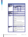
IND246 Specifications
Environmental
Protection
IP66 (comparable to Type 4x)
Operating
Environment
The terminal can be operated at temperatures ranging from −10° to 40° C (14° to
104° F) at 10% to 95% relative humidity, non-condensing.
Hazardous Areas
The IND246 terminal cannot be operated in areas classified as Hazardous because of
combustible or explosive atmospheres in those areas. Contact an authorized METTLER
TOLEDO representative for information about hazardous area applications.
Power
AC version: Operates at 85–264 VAC, 49–61 Hz and includes a power cord configured
for the country of use.
Battery version: Operates from internal NiMH battery pack
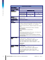
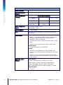
Power
Consumption
Refer to Table 1-2 for details of the AC version. Values shown are with internal COM2/DIO
option and Ethernet option installed and load cell input loaded with 8 x 350Ω load cells.
Refer to Table 1-3 for Refer to Table 1-4 for details of the battery life for the battery
powered version.
Power
Consumption
Refer to Table 1-2 for the AC version; Table 1-3 for IND246 POWERCELL; and Table 1-4
for the battery version.
Values shown in Table 1-2 are for an IND246 terminal with the internal COM2/DIO and
Ethernet options installed, and input from 8 x 350Ω load cells.
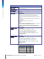
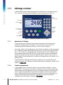
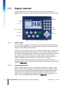
Display
Backlit 240 x 96 dot graphic LCD including weight display, weight units, gross/net
indication and graphic symbols for motion and center of zero, SmartTrac, operator
prompts and data entry display. Update rate of 12 updates per second.
Basic weight mode: 27 mm (1.1 in) high weight display
Application mode: 20 mm (0.8 in) high weight display
Weight Display
Maximum displayed resolution of 50,000 divisions.
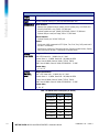
Scale Types
Analog load cells (AC or battery models), POWERCELL PDX, GDD, SLC611D or
SLD615D load cells (POWERCELL model),
Number of Cells
AC Version: From one to ten 350-ohm load cells (2 or 3 mV/V)
Battery Version: From one to four 350-ohm load cells (2 or 3 mV/V)
POWERCELL Version: Up to 12 POWERCELL PDX, GDD, SLC611D or SLB615D load cells
Number of Scales
One
Analog
Update Rate
Internal analog: 366 MHz
POWERCELL
Update Rate
Update Rates (Hz)
Update Rate, Type
Vehicle, 12 load cells
Load Cell Network
25
Synchronized Continuous Weight
Output
USB, COM1,
COM2, Ethernet
17 - 25
Load Cell
Excitation Voltage
AC Version: 10 VDC
Battery Version : 5 V DC

1-4
METTLER TOLEDO IND246 and IND246 POWERCELL Installation Manual
64084463 | 03 | 12/2017
Introduction
IND246 Specifications
Minimum
Sensitivity
0.1 microvolt per increment
Keypad
25 keys; polyester overlay (PET) with polycarbonate display lens
Communications
Serial Interfaces
Standard: One isolated serial port (COM1) RS-232 (analog only); RS-232/RS-422-
RS-485 (POWERCELL only), 300 to 115,200 baud
Optional isolated serial port: (COM2) RS-232/485, 300 to 115,200 baud
Optional USB port: serial port bridge, 300 to 115,200 baud
Ethernet Interface
Optional Ethernet port: 10/100 TCP/IP port
Protocol
Serial Inputs: ASCII commands for CTPZ (Clear, Tare, Print, Zero), SICS (most level 0
and level 1 commands)
Serial Outputs: Continuous, Extended continuous, Demand (limited formats), Reports,
SICS (most level 0 and level 1 commands) or Variable Access
Approvals,
Analog Version
Weights and Measures
USA: NTEP Class III/IIIL - 10,000d; Cert. #11-040
Canada: Class III - 10,000d; Class IIIHD - 20,000d; AM-5819
Europe: Class III 6000e, Class IIII 1000e; TC7918, T8030
OIML: Class III 6000e, Class IIII 1000e; R76/2006-NL1-15.49R1
Product Safety
UL, cUL, CE
Approvals,
POWERCELL
Version
Weights and Measures
USA: : NTEP Class III/IIIL - 10,000d; Cert. #11-040
Canada: Class III - 10,000d; Class IIIHD - 20,000d; AM-5819
Europe: Class III 6000e, Class IIII 1000e; TC7918, T8426
OIML: Class III 6000e, Class IIII 1000e; R76/2006-NL1-15.49R1
Product Safety
UL, cUL, CE
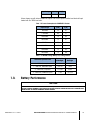
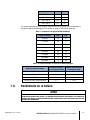
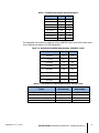
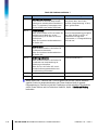
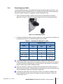
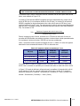
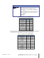
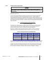
Table 1-2: IND246 Power Consumption (AC Source)
Input Voltage I (mA) P (W)
85V/50 Hz 167 7.9
110 V/50 Hz 133 7.7
240 V/50 Hz 64 7.9
264 V/50 Hz 59 7.9
85 V/60 Hz 163 7.9
110 V/60 Hz 128 7.7
240 V/60 Hz 62 7.9

64084463 | 03 | 12/2017
METTLER TOLEDO IND246 and IND246 POWERCELL Installation Manual
1-5
Input Voltage I (mA) P (W)
264 V/60 Hz 58 8.0
Values shown are with internal COM2/DIO option and Ethernet option installed and load cell input
loaded with 8 x 350Ω load cells.
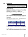
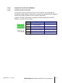
Table 1-3: Power Consumption for POWERCELL Version
Input Voltage I(mA) P(W)
85V/50Hz 112 5.7
110V/50Hz 94 6
240V/50Hz 73 8.4
264V/50Hz 72 8.7
85V/60Hz 108 5.8
110V/60Hz 92 6
240V/60Hz 73 8.3
264V/60Hz 73 8.6
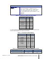
Table 1-4: IND246 Average Battery Life, Analog Version
Continuous Operation Load
Battery Life
w/Backlight
Battery Life w/o
Backlight
1- 350Ω cell, no options 21.5 hrs 49 hrs
1 – 350Ω cell, COM2/DIO option 12.5 hrs 19 hrs
4 – 350Ω cells, no options 17. 5 hrs 32 hrs
4 – 350Ω cells, COM2/DIO option 11 hrs 15.5 hrs
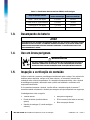
1.3. Battery Performance
NOTICE
NiMH BATTERIES SLOWLY DISCHARGE WHEN NOT USED (FOR EXAMPLE WHEN STORED FOR FUTURE USE).
BATTERY OPERATED TERMINALS AND SPARE NiMH BATTERY PACKS IN STORAGE MUST BE FULLY CHARGED EVERY
THREE MONTHS TO PREVENT PERMANENT BATTERY DAMAGE.

1-6
METTLER TOLEDO IND246 and IND246 POWERCELL Installation Manual
64084463 | 03 | 12/2017
Introduction
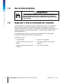
1.4. Use in Hazardous Areas
WARNING
DO NOT USE THE IND246 TERMINAL IN AREAS CLASSIFIED AS HAZARDOUS BECAUSE OF
COMBUSTIBLE OR EXPLOSIVE ATMOSPHERES. CONTACT AN AUTHORIZED METTLER TOLEDO
REPRESENTATIVE FOR INFORMATION ABOUT HAZARDOUS AREA APPLICATIONS.
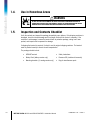
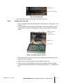
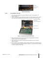
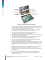
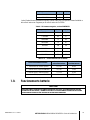
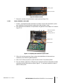
1.5. Inspection and Contents Checklist
Verify the contents and inspect the package immediately upon delivery. If the shipping container is
damaged, check for internal damage and file a freight claim with the carrier if necessary. If the
container is not damaged, remove the terminal from its protective package, noting how it was
packed, and inspect each component for damage.
If shipping the terminal is required, it is best to use the original shipping container. The terminal
must be packed correctly to ensure its safe transportation.
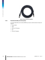
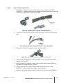
The package should include:
• IND246 Terminal
• Battery Pack (battery version only)
• Mounting brackets (2; analog version only)
• Safety Instructions
• Resource CD (includes all manuals)
• Bag of miscellaneous parts

64084463 | 03 | 12/2017
METTLER TOLEDO IND246 and IND246 POWERCELL Installation Manual
1-7
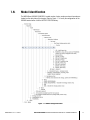
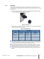
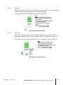
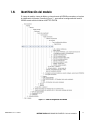
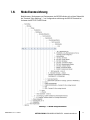
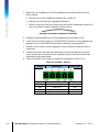
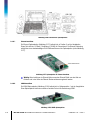
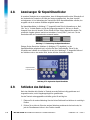
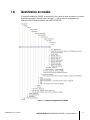
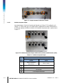
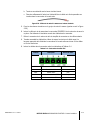
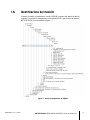
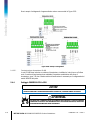
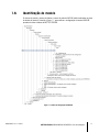
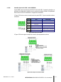
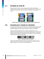
1.6. Model Identification
The IND246 and IND246 POWERCELL model number, factory number and serial number are
located on the data plate of the terminal. Refer to Figure 1-1 to verify the configuration of the
IND246 terminal when it left the METTLER TOLEDO factory.
Figure 1-1: IND246 Configuration Chart

1-8
METTLER TOLEDO IND246 and IND246 POWERCELL Installation Manual
64084463 | 03 | 12/2017
Introduction
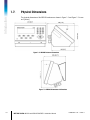
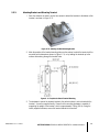
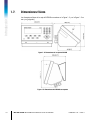
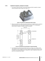
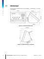
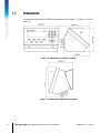
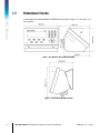
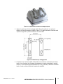
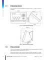
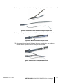
1.7. Physical Dimensions
The physical dimensions of the IND246 enclosure are shown in Figure 1-2 and Figure 1-3 in mm
and [inches].
Figure 1-2: IND246 Enclosure Dimensions
Figure 1-3: IND246 Dimensions with Brackets

64084463 | 03 | 12/2017
METTLER TOLEDO IND246 and IND246 POWERCELL Installation Manual
1-9
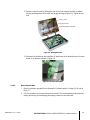
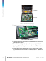
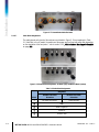
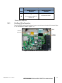
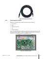
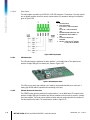
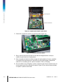
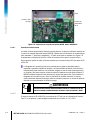
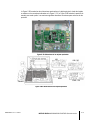
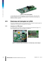
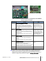
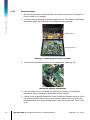
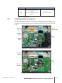
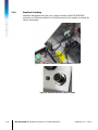
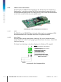
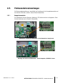
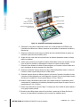
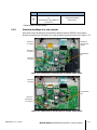
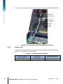
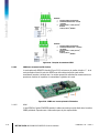
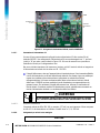
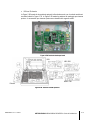
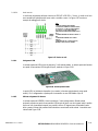
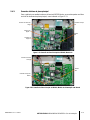
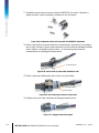
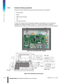
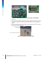
1.8. Main PCB
The IND246 terminal’s main printed circuit board (PCB) provides the analog load cell scale
interface, as well as the COM1 RS-232 serial port. The IND246 POWERCELL main board provides
the load cell interface and a standard COM1 RS-232/RS-422/RS-485 isolated serial port.
The main board also contains the power input connection (for either AC supply or battery,
depending on the model), display interface, keypad interface and six-position DIP switch.
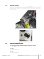
An SD memory card socket is mounted to the PCB to support the optional SD memory and bus
connectors are included for the option boards.
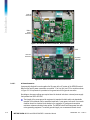
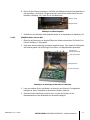
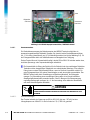
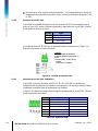
1.8.1. SD Memory
An SD Memory card is included as a standard feature of the analog version of the IND246, and is
available as an option for the POWERCELL version. The card provides a medium on which to store
files such as Alibi memory, transaction records in the vehicle application, IDs in the counting
application and target weights in the checkweighing application.
The SD memory can be used to extract and save the configuration and calibration settings of the
terminal. These can then be restored to the terminal or loaded to a different terminal.
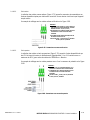
1.9. Scale Bases
1.9.1. Analog
The standard IND246 terminal supports analog scale bases and provides either 10 volts (AC
version) or 5 volts (battery version) of excitation to drive analog load cells. Up to four (battery
version) or ten (AC version) 350Ω load cells can be powered by the terminal.
A six wire load cell connection is provided with sense lines to help maintain accuracy as the load
cell cable resistance changes with temperature variations.
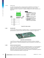
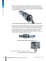
1.9.2. POWERCELL
The IND246 POWERCELL terminal supports scale bases that use POWERCELL PDX, GDD,
SLC611D or SLB615D load cells. Up to 12 load cells can be configured in a single scale platform.
The load cell network provides monitoring and logging of a variety of factors that can affect system
integrity, including weighing errors, overloads and network health. The specific characteristics differ
by type of load cell.

1-10
METTLER TOLEDO IND246 and IND246 POWERCELL Installation Manual
64084463 | 03 | 12/2017
Introduction
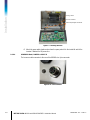
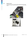
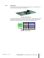
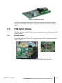
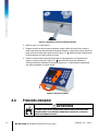
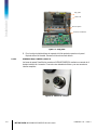
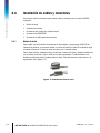
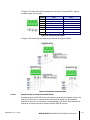
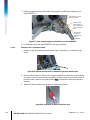
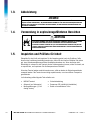
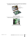
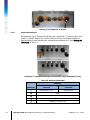
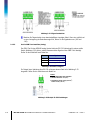
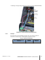
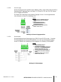
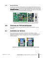
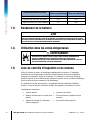
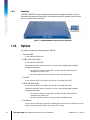
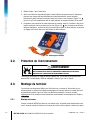
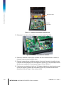
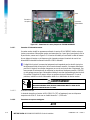
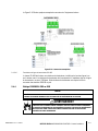
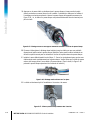
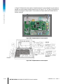
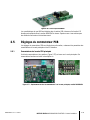
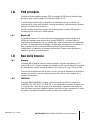
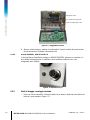
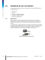
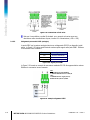
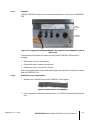
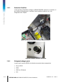
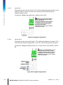
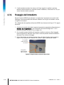
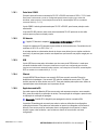
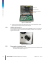
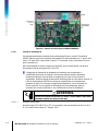
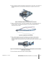
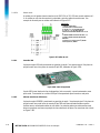
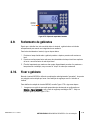
1.9.3. PowerDeck
The IND246 POWERCELL supports PowerDeck
TM
weighing platforms. These provide calibration
without weights for fast installation and visual guidance for leveling the floor platform.
Figure 1-4: IND246 POWERCELL with PowerDeck Platform
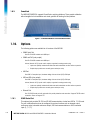
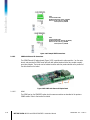
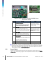
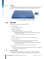
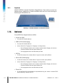
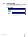
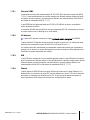
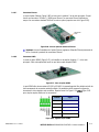
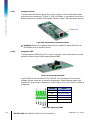
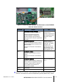
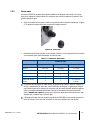
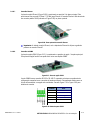
1.10. Options
The following options are available for all versions of the IND246:
• COM2 Serial Port
One RS-232/485 isolated serial COM port
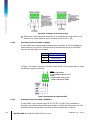
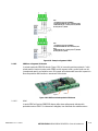
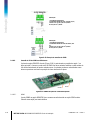
•
COM2 and DIO (relay output)
One RS-232/485 isolated serial COM port
Internal, discrete I/O (2 inputs and 4 outputs; supported in analog version only)
─ Inputs are optically isolated solid state and switch selectable as either active or passive
─ Output relays provide one normally open contact per relay
•
USB Port
One USB 2.0 compliant port, hardware bridge. Acts as virtual (UCP) COM port
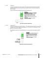
•
USB and DIO (relay output)
One USB 2.0 compliant port, hardware bridge. Acts as virtual (UCP) COM port
Internal, discrete I/O (2 inputs and 4 outputs; supported in analog version only)
─ Inputs are optically isolated solid state and switch selectable as either active or passive
─ Output relays provide one normally open contact per relay
•
Ethernet Port
One 10/100 Ethernet port with automatic link polarity detection and correction. Supports TCP/IP socket
connection. Does not support FTP
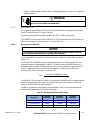
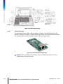
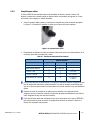
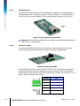
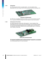
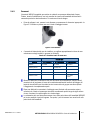
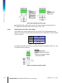
1.10.1. COM2 Serial Port
This optional port provides RS-232 and RS-485 communication at rates from 300 to 115.2k baud.
The port is bidirectional and can be configured for various functions such as demand output,
continuous output, extended continuous output, SICS host communications or ASCII command
input (C, T, P, Z).
La pagina sta caricando ...
La pagina sta caricando ...
La pagina sta caricando ...
La pagina sta caricando ...
La pagina sta caricando ...
La pagina sta caricando ...
La pagina sta caricando ...
La pagina sta caricando ...
La pagina sta caricando ...
La pagina sta caricando ...
La pagina sta caricando ...
La pagina sta caricando ...
La pagina sta caricando ...
La pagina sta caricando ...
La pagina sta caricando ...
La pagina sta caricando ...
La pagina sta caricando ...
La pagina sta caricando ...
La pagina sta caricando ...
La pagina sta caricando ...
La pagina sta caricando ...
La pagina sta caricando ...
La pagina sta caricando ...
La pagina sta caricando ...
La pagina sta caricando ...
La pagina sta caricando ...
La pagina sta caricando ...
La pagina sta caricando ...
La pagina sta caricando ...
La pagina sta caricando ...
La pagina sta caricando ...
La pagina sta caricando ...
La pagina sta caricando ...
La pagina sta caricando ...
La pagina sta caricando ...
La pagina sta caricando ...
La pagina sta caricando ...
La pagina sta caricando ...
La pagina sta caricando ...
La pagina sta caricando ...
La pagina sta caricando ...
La pagina sta caricando ...
La pagina sta caricando ...
La pagina sta caricando ...
La pagina sta caricando ...
La pagina sta caricando ...
La pagina sta caricando ...
La pagina sta caricando ...
La pagina sta caricando ...
La pagina sta caricando ...
La pagina sta caricando ...
La pagina sta caricando ...
La pagina sta caricando ...
La pagina sta caricando ...
La pagina sta caricando ...
La pagina sta caricando ...
La pagina sta caricando ...
La pagina sta caricando ...
La pagina sta caricando ...
La pagina sta caricando ...
La pagina sta caricando ...
La pagina sta caricando ...
La pagina sta caricando ...
La pagina sta caricando ...
La pagina sta caricando ...
La pagina sta caricando ...
La pagina sta caricando ...
La pagina sta caricando ...
La pagina sta caricando ...
La pagina sta caricando ...
La pagina sta caricando ...
La pagina sta caricando ...
La pagina sta caricando ...
La pagina sta caricando ...
La pagina sta caricando ...
La pagina sta caricando ...
La pagina sta caricando ...
La pagina sta caricando ...
La pagina sta caricando ...
La pagina sta caricando ...
La pagina sta caricando ...
La pagina sta caricando ...
La pagina sta caricando ...
La pagina sta caricando ...
La pagina sta caricando ...
La pagina sta caricando ...
La pagina sta caricando ...
La pagina sta caricando ...
La pagina sta caricando ...
La pagina sta caricando ...
La pagina sta caricando ...
La pagina sta caricando ...
La pagina sta caricando ...
La pagina sta caricando ...
La pagina sta caricando ...
La pagina sta caricando ...
La pagina sta caricando ...
La pagina sta caricando ...
La pagina sta caricando ...
La pagina sta caricando ...
La pagina sta caricando ...
La pagina sta caricando ...
La pagina sta caricando ...
La pagina sta caricando ...
La pagina sta caricando ...
La pagina sta caricando ...
La pagina sta caricando ...
La pagina sta caricando ...
La pagina sta caricando ...
La pagina sta caricando ...
La pagina sta caricando ...
La pagina sta caricando ...
La pagina sta caricando ...
La pagina sta caricando ...
La pagina sta caricando ...
La pagina sta caricando ...
La pagina sta caricando ...
La pagina sta caricando ...
La pagina sta caricando ...
La pagina sta caricando ...
La pagina sta caricando ...
La pagina sta caricando ...
La pagina sta caricando ...
La pagina sta caricando ...
La pagina sta caricando ...
La pagina sta caricando ...
La pagina sta caricando ...
La pagina sta caricando ...
La pagina sta caricando ...
La pagina sta caricando ...
La pagina sta caricando ...
La pagina sta caricando ...
La pagina sta caricando ...
La pagina sta caricando ...
La pagina sta caricando ...
La pagina sta caricando ...
La pagina sta caricando ...
La pagina sta caricando ...
La pagina sta caricando ...
La pagina sta caricando ...
La pagina sta caricando ...
La pagina sta caricando ...
La pagina sta caricando ...
La pagina sta caricando ...
La pagina sta caricando ...
La pagina sta caricando ...
La pagina sta caricando ...
La pagina sta caricando ...
La pagina sta caricando ...
La pagina sta caricando ...
La pagina sta caricando ...
La pagina sta caricando ...
La pagina sta caricando ...
La pagina sta caricando ...
La pagina sta caricando ...
La pagina sta caricando ...
La pagina sta caricando ...
La pagina sta caricando ...
La pagina sta caricando ...
La pagina sta caricando ...
La pagina sta caricando ...
La pagina sta caricando ...
La pagina sta caricando ...
La pagina sta caricando ...
La pagina sta caricando ...
La pagina sta caricando ...
La pagina sta caricando ...
La pagina sta caricando ...
La pagina sta caricando ...
La pagina sta caricando ...
La pagina sta caricando ...
La pagina sta caricando ...
La pagina sta caricando ...
La pagina sta caricando ...
La pagina sta caricando ...
La pagina sta caricando ...
La pagina sta caricando ...
La pagina sta caricando ...
La pagina sta caricando ...
La pagina sta caricando ...
La pagina sta caricando ...
La pagina sta caricando ...
La pagina sta caricando ...
La pagina sta caricando ...
La pagina sta caricando ...
La pagina sta caricando ...
La pagina sta caricando ...
La pagina sta caricando ...
La pagina sta caricando ...
La pagina sta caricando ...
La pagina sta caricando ...
La pagina sta caricando ...
La pagina sta caricando ...
La pagina sta caricando ...
La pagina sta caricando ...
La pagina sta caricando ...
La pagina sta caricando ...
La pagina sta caricando ...
La pagina sta caricando ...
La pagina sta caricando ...
La pagina sta caricando ...
La pagina sta caricando ...
La pagina sta caricando ...
La pagina sta caricando ...
La pagina sta caricando ...
La pagina sta caricando ...
La pagina sta caricando ...
La pagina sta caricando ...
La pagina sta caricando ...
La pagina sta caricando ...
La pagina sta caricando ...
La pagina sta caricando ...
La pagina sta caricando ...
La pagina sta caricando ...
La pagina sta caricando ...
La pagina sta caricando ...
La pagina sta caricando ...
La pagina sta caricando ...
La pagina sta caricando ...
La pagina sta caricando ...
La pagina sta caricando ...
La pagina sta caricando ...
La pagina sta caricando ...
La pagina sta caricando ...
La pagina sta caricando ...
La pagina sta caricando ...
La pagina sta caricando ...
La pagina sta caricando ...
La pagina sta caricando ...
La pagina sta caricando ...
La pagina sta caricando ...
La pagina sta caricando ...
La pagina sta caricando ...
La pagina sta caricando ...
La pagina sta caricando ...
La pagina sta caricando ...
La pagina sta caricando ...
La pagina sta caricando ...
La pagina sta caricando ...
La pagina sta caricando ...
La pagina sta caricando ...
La pagina sta caricando ...
La pagina sta caricando ...
La pagina sta caricando ...
La pagina sta caricando ...
La pagina sta caricando ...
La pagina sta caricando ...
La pagina sta caricando ...
La pagina sta caricando ...
La pagina sta caricando ...
La pagina sta caricando ...
La pagina sta caricando ...
La pagina sta caricando ...
La pagina sta caricando ...
La pagina sta caricando ...
La pagina sta caricando ...
La pagina sta caricando ...
La pagina sta caricando ...
La pagina sta caricando ...
La pagina sta caricando ...
La pagina sta caricando ...
La pagina sta caricando ...
La pagina sta caricando ...
La pagina sta caricando ...
La pagina sta caricando ...
La pagina sta caricando ...
La pagina sta caricando ...
La pagina sta caricando ...
La pagina sta caricando ...
La pagina sta caricando ...
La pagina sta caricando ...
La pagina sta caricando ...
La pagina sta caricando ...
La pagina sta caricando ...
La pagina sta caricando ...
La pagina sta caricando ...
La pagina sta caricando ...
La pagina sta caricando ...
La pagina sta caricando ...
La pagina sta caricando ...
La pagina sta caricando ...
La pagina sta caricando ...
La pagina sta caricando ...
La pagina sta caricando ...
La pagina sta caricando ...
La pagina sta caricando ...
La pagina sta caricando ...
La pagina sta caricando ...
La pagina sta caricando ...
La pagina sta caricando ...
La pagina sta caricando ...
La pagina sta caricando ...
La pagina sta caricando ...
La pagina sta caricando ...
La pagina sta caricando ...
La pagina sta caricando ...
La pagina sta caricando ...
La pagina sta caricando ...
La pagina sta caricando ...
La pagina sta caricando ...
La pagina sta caricando ...
La pagina sta caricando ...
La pagina sta caricando ...
La pagina sta caricando ...
La pagina sta caricando ...
La pagina sta caricando ...
La pagina sta caricando ...
La pagina sta caricando ...
La pagina sta caricando ...
La pagina sta caricando ...
La pagina sta caricando ...
La pagina sta caricando ...
La pagina sta caricando ...
La pagina sta caricando ...
La pagina sta caricando ...
La pagina sta caricando ...
La pagina sta caricando ...
La pagina sta caricando ...
La pagina sta caricando ...
La pagina sta caricando ...
La pagina sta caricando ...
La pagina sta caricando ...
La pagina sta caricando ...
La pagina sta caricando ...
La pagina sta caricando ...
La pagina sta caricando ...
La pagina sta caricando ...
La pagina sta caricando ...
La pagina sta caricando ...
La pagina sta caricando ...
La pagina sta caricando ...
La pagina sta caricando ...
La pagina sta caricando ...
La pagina sta caricando ...
La pagina sta caricando ...
La pagina sta caricando ...
La pagina sta caricando ...
La pagina sta caricando ...
La pagina sta caricando ...
La pagina sta caricando ...
La pagina sta caricando ...
La pagina sta caricando ...
La pagina sta caricando ...
La pagina sta caricando ...
La pagina sta caricando ...
La pagina sta caricando ...
La pagina sta caricando ...
La pagina sta caricando ...
La pagina sta caricando ...
La pagina sta caricando ...
La pagina sta caricando ...
La pagina sta caricando ...
La pagina sta caricando ...
La pagina sta caricando ...
La pagina sta caricando ...
La pagina sta caricando ...
La pagina sta caricando ...
La pagina sta caricando ...
La pagina sta caricando ...
La pagina sta caricando ...
-
 1
1
-
 2
2
-
 3
3
-
 4
4
-
 5
5
-
 6
6
-
 7
7
-
 8
8
-
 9
9
-
 10
10
-
 11
11
-
 12
12
-
 13
13
-
 14
14
-
 15
15
-
 16
16
-
 17
17
-
 18
18
-
 19
19
-
 20
20
-
 21
21
-
 22
22
-
 23
23
-
 24
24
-
 25
25
-
 26
26
-
 27
27
-
 28
28
-
 29
29
-
 30
30
-
 31
31
-
 32
32
-
 33
33
-
 34
34
-
 35
35
-
 36
36
-
 37
37
-
 38
38
-
 39
39
-
 40
40
-
 41
41
-
 42
42
-
 43
43
-
 44
44
-
 45
45
-
 46
46
-
 47
47
-
 48
48
-
 49
49
-
 50
50
-
 51
51
-
 52
52
-
 53
53
-
 54
54
-
 55
55
-
 56
56
-
 57
57
-
 58
58
-
 59
59
-
 60
60
-
 61
61
-
 62
62
-
 63
63
-
 64
64
-
 65
65
-
 66
66
-
 67
67
-
 68
68
-
 69
69
-
 70
70
-
 71
71
-
 72
72
-
 73
73
-
 74
74
-
 75
75
-
 76
76
-
 77
77
-
 78
78
-
 79
79
-
 80
80
-
 81
81
-
 82
82
-
 83
83
-
 84
84
-
 85
85
-
 86
86
-
 87
87
-
 88
88
-
 89
89
-
 90
90
-
 91
91
-
 92
92
-
 93
93
-
 94
94
-
 95
95
-
 96
96
-
 97
97
-
 98
98
-
 99
99
-
 100
100
-
 101
101
-
 102
102
-
 103
103
-
 104
104
-
 105
105
-
 106
106
-
 107
107
-
 108
108
-
 109
109
-
 110
110
-
 111
111
-
 112
112
-
 113
113
-
 114
114
-
 115
115
-
 116
116
-
 117
117
-
 118
118
-
 119
119
-
 120
120
-
 121
121
-
 122
122
-
 123
123
-
 124
124
-
 125
125
-
 126
126
-
 127
127
-
 128
128
-
 129
129
-
 130
130
-
 131
131
-
 132
132
-
 133
133
-
 134
134
-
 135
135
-
 136
136
-
 137
137
-
 138
138
-
 139
139
-
 140
140
-
 141
141
-
 142
142
-
 143
143
-
 144
144
-
 145
145
-
 146
146
-
 147
147
-
 148
148
-
 149
149
-
 150
150
-
 151
151
-
 152
152
-
 153
153
-
 154
154
-
 155
155
-
 156
156
-
 157
157
-
 158
158
-
 159
159
-
 160
160
-
 161
161
-
 162
162
-
 163
163
-
 164
164
-
 165
165
-
 166
166
-
 167
167
-
 168
168
-
 169
169
-
 170
170
-
 171
171
-
 172
172
-
 173
173
-
 174
174
-
 175
175
-
 176
176
-
 177
177
-
 178
178
-
 179
179
-
 180
180
-
 181
181
-
 182
182
-
 183
183
-
 184
184
-
 185
185
-
 186
186
-
 187
187
-
 188
188
-
 189
189
-
 190
190
-
 191
191
-
 192
192
-
 193
193
-
 194
194
-
 195
195
-
 196
196
-
 197
197
-
 198
198
-
 199
199
-
 200
200
-
 201
201
-
 202
202
-
 203
203
-
 204
204
-
 205
205
-
 206
206
-
 207
207
-
 208
208
-
 209
209
-
 210
210
-
 211
211
-
 212
212
-
 213
213
-
 214
214
-
 215
215
-
 216
216
-
 217
217
-
 218
218
-
 219
219
-
 220
220
-
 221
221
-
 222
222
-
 223
223
-
 224
224
-
 225
225
-
 226
226
-
 227
227
-
 228
228
-
 229
229
-
 230
230
-
 231
231
-
 232
232
-
 233
233
-
 234
234
-
 235
235
-
 236
236
-
 237
237
-
 238
238
-
 239
239
-
 240
240
-
 241
241
-
 242
242
-
 243
243
-
 244
244
-
 245
245
-
 246
246
-
 247
247
-
 248
248
-
 249
249
-
 250
250
-
 251
251
-
 252
252
-
 253
253
-
 254
254
-
 255
255
-
 256
256
-
 257
257
-
 258
258
-
 259
259
-
 260
260
-
 261
261
-
 262
262
-
 263
263
-
 264
264
-
 265
265
-
 266
266
-
 267
267
-
 268
268
-
 269
269
-
 270
270
-
 271
271
-
 272
272
-
 273
273
-
 274
274
-
 275
275
-
 276
276
-
 277
277
-
 278
278
-
 279
279
-
 280
280
-
 281
281
-
 282
282
-
 283
283
-
 284
284
-
 285
285
-
 286
286
-
 287
287
-
 288
288
-
 289
289
-
 290
290
-
 291
291
-
 292
292
-
 293
293
-
 294
294
-
 295
295
-
 296
296
-
 297
297
-
 298
298
-
 299
299
-
 300
300
-
 301
301
-
 302
302
-
 303
303
-
 304
304
-
 305
305
-
 306
306
-
 307
307
-
 308
308
-
 309
309
-
 310
310
-
 311
311
-
 312
312
-
 313
313
-
 314
314
-
 315
315
-
 316
316
-
 317
317
-
 318
318
-
 319
319
-
 320
320
-
 321
321
-
 322
322
-
 323
323
-
 324
324
-
 325
325
-
 326
326
-
 327
327
-
 328
328
-
 329
329
-
 330
330
-
 331
331
-
 332
332
-
 333
333
-
 334
334
-
 335
335
-
 336
336
-
 337
337
-
 338
338
-
 339
339
-
 340
340
-
 341
341
-
 342
342
-
 343
343
-
 344
344
-
 345
345
-
 346
346
-
 347
347
-
 348
348
-
 349
349
-
 350
350
-
 351
351
-
 352
352
-
 353
353
-
 354
354
-
 355
355
-
 356
356
-
 357
357
-
 358
358
-
 359
359
-
 360
360
-
 361
361
-
 362
362
-
 363
363
-
 364
364
-
 365
365
-
 366
366
-
 367
367
-
 368
368
-
 369
369
-
 370
370
-
 371
371
-
 372
372
-
 373
373
-
 374
374
-
 375
375
-
 376
376
-
 377
377
-
 378
378
-
 379
379
-
 380
380


Mettler Toledo IND246 Terminal Guida d'installazione
- Tipo
- Guida d'installazione
- Questo manuale è adatto anche per
in altre lingue
Documenti correlati
-
Mettler Toledo IND570 Istruzioni per l'uso
-
-
-
-
-
-
-
-
-
Altri documenti
-
Samsung SSA-P400T Manuale utente
-
Ohaus Defender Series Guida utente
-
Boynq Alibi speaker & webcam Manuale utente
-
JVC LVT1650-001B Manuale utente
-
AVENTICS Series NL Assembly Instructions
-
ETC Unison Paradigm P-TS7 Guida d'installazione
-
Honeywell HEV28C Quick Install Manual
-
HellermannTyton Reliseal Series Installation Instructions Manual
-
 Allen-Bradley 2711-NP3 Installation Instructions Manual
