
A
B
Photocell
Its self-aligning photocell, consisting of a modular infrared Transmitter and Receiver.
It is classed as a safety device.
Breaking the luminous beam causes the state of the electric contact on the Receiver
to be switched.
1. TECHNICAL SPECIFICATIONS
POWER SUPPLY 24Vac/Vdc
POWER CONSUMPTION TX 22 mA RX 50 mA
NOMINAL DISTANCE 15 metres
ALIGNMENT automatic
OBSTACLE DETECTION TIME 13 milliseconds
OPERATING TEMPERATURE -20°C +55 °C
MAX CAPACITY ON CONTACTS 1A-28 Vdc / 0.5A-120 Vac
TYPE OF CONTACTS NO / NC
INSTALLATION wall / stand
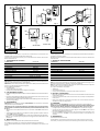
DIMENSION see fig. 1
ENGLISH
2. FITTING
N.B.: To ensure maximum efficiency of the system, position the Receiver (fig.2 - item
A) and the Transmitter (fig.2 - item B) so that they are aligned.
N.B.: If two pairs of photocells are to be employed, place the Receivers on opposite
sides in order to avoid mutual interference.
Two types of installation are possible:
Wall (fig.3).
On special stand (fig.4).
Carry out the preparatory work for the electrical connections.
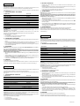
3. ELECTRIC CONNECTIONS
Effect the necessary elestrical connections to the terminal blocks of the Receiver
and Trasmitter (fig. 5).
Connect wiring to the electronic control unit and any other photocells presents
in the system.
Refer to the diagrams contained in the electronic control unit instructions for
details of the various configurations.
4. ALIGNMENT
N.B.: The photocell is self-aligning and requires no adjustment after installation.
Caution: For a correct alignment it is absolutely necessary to apply both front panels
to the enclosures before starting the alignment procedure, as shown in fig. 6.
Energise the photocell and check that LED DL1 is lit on both Receiver (fig. 5).
Check that the photocells are correctly aligned. The LED DL2 on the receiver
illuminates when alignment is correct.
N.B.: If the LED DL2 on the Receiver is off, first check that the power supply to the
device is turned on, LED DL1 on, then adjust the position of the Receiver as
required.
5. MAINTENANCE
The VISION is maintenance free.
It is advisable to check that the system is in good working order every six months.
If necessary, the front panel can be removed using a screwdriver as shown in Fig. 7.
Fotocellula
La fotocellula autoallineante, composta da un Trasmettitore ed un Ricevitore a
raggi infrarossi modulati, è un dispositivo di sicurezza.
L'oscuramento del fascio luminoso, provoca il cambiamento di stato del contatto
elettrico sul Ricevitore.
1. CARATTERISTICHE TECNICHE
ALIMENTAZIONE 24 Vac/Vdc
ASSORBIMENTO TX 22 mA RX 50 mA
PORTATA NOMINALE 15 metri
ALLINEAMENTO automatico
TEMPO DI RILEVAMENTO OSTACOLO 13 millisecondi
TEMPERATURA AMBIENTE -20°C +55°C
PORTATA MAX SUI CONTATTI 1A-28 Vdc / 0,5A-120 Vac
TIPO DI CONTATTI NO / NC
INSTALLAZIONE a parete / su colonnetta
DIMENSIONI vedi fig. 1
ITALIANO
2. MONTAGGIO
Attenzione: per ottenere la massima efficienza del sistema, collocare il Ricevitore
(fig.2 - rif.A) e il Trasmettitore (fig.2 - rif.B) allineati.
Attenzione: nel caso siano previste due coppie di fotocellule, per evitare interferenze
reciproche, disporre i Ricevitori su lati opposti.
Sono possibili due installazioni:
A parete (fig.3).
Su apposita colonnetta (fig.4).
Eseguire le predisposizioni per i collegamenti elettrici.
3. COLLEGAMENTI ELETTRICI
Eseguire i collegamenti elettrici sulle morsettiere del Ricevitore e del Trasmettitore
(fig.5).
Eseguire i cablaggi elettrici allapparecchiatura elettronica di comando ed ad
altre eventuali fotocellule presenti nellimpianto.
Fare riferimento agli schemi riportati nelle istruzioni delle apparecchiature per le
diverse configurazioni.
4. ALLINEAMENTO
Attenzione: le fotocellule sono dispositivi autoallineanti e non prevedono operazioni
di regolazione dopo linstallazione.
Attenzione: per un corretto allineamento è assolutamente necessario applicare
i due frontalini sui contenitori prima di iniziare la procedura di allineamento,come
da fig. 6.
Alimentare la fotocellula verificando laccensione del led DL1 sul Ricevitore
(fig.5).
Verificare il corretto allineamento delle fotocellule, segnalato dallaccensione
del led DL2 del Ricevitore (fig.5).
Nota bene: nel caso il led DL2 sia spento verificare che il dispositivo sia alimentato,
DL1 acceso, e quindi apportare gli opportuni aggiustamenti alla posizione del
Ricevitore.
5. MANUTENZIONE
Il dispositivo non richiede particolari operazioni di manutenzione.
Si consiglia di controllare con cadenza semestrale l'efficienza del sistema.
In caso di necessità il frontalino può essere rimosso con l'ausilio di un cacciavite come
da fig.7.
Fig. 1
Fig. 2
Fig. 3
Fig. 4
Fig. 6
Fig. 5
28
53
95
NO NC 1 2 3
NO NC COM
DL1
DL2
- +
~ ~
24 Vac/Vdc
1 2
- +
~ ~
24 Vac/Vdc
1
2
Fig. 7
La pagina si sta caricando...
-
 1
1
-
 2
2


in altre lingue
- English: Genius Vision Operating instructions
- français: Genius Vision Mode d'emploi
- español: Genius Vision Instrucciones de operación
- Deutsch: Genius Vision Bedienungsanleitung
Documenti correlati
-
Genius Vision Istruzioni per l'uso
-
-
-
-
-
-
-
-