
microchip.com
SiC Gate Driver
Quick Start Guide
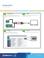
Geng Started
Insert ASB-014 adapter board into PICkit™ 4 and
connect programming cable from ASB-014 to driver
board.
Connect
Connect micro-USB cable from PICkit™ 4 to computer.
Apply power to driver board.
1 2
Congure
Open Intelligent Conguration Tool (ICT),
select your board, and enter desired settings.
Compile
43
Click Compile to generate conguration hex le.
Micro-B USB USB
2ASC Series
62EMI Series
ASB-014

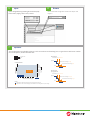
Open
Open Integrated Programming Environment (IPE).
Enter Device, Apply; select Tool, Connect.
5 6
Opmize
Test conguration using double-pulse test. Look at overshoot and switching loss. For gate drivers with lesser number
of turn o options, choose the lower limit.
Vgs operation
Vth
SiC MOSFET Datasheet
Legend
Optimization for Eoff with multi-level turn-off voltage less than equal Vgth
Multi-Level Turn-Off Voltage(V)
+Vgs
12345678910
Eoff Optimization
Vds overshot and
ringing Optimization
Vds Overshoot &
Eoff (mJ)
Dwell Time(ns)
Optimization for Vds Overshoot & Ringing with multi-level turn-off voltage less than equal to 2*Vgth
1 us
900 ns
800 ns
700 ns
600 ns
500 ns
400 ns
300 ns
200 ns
100 ns
50 ns
Vds overshot
and ringing
Optimization
Eoff Optimization
Dwell Time(ns) ~50 ns <200 ns
Vgs(max)
First level Turn-Off voltage < =Vgth
Second level Turn-Off voltage <Vgth
Vgs(min)
T(ns)
Dwell Time(ns) ~250 ns <650 ns
Vgs(max)
First level Turn-Off voltage <=2* Vgth
Second level Turn-Off voltage <=Vgth
Vgs(min)
T(ns)
7
Browse
Browse and select conguraon hex le from step 4. Click
Program.

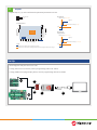
Set Up
Note: Diagrams and parts are not to scale.
If using 2ASC series core board, connect programming cable at A1 and B1.
If using 62EM1 series plug-and-play board, connect programming cable at A2 and B2.
Repeat
Repeat steps 3, 4, 6, and 7 until desired operational parameters are met.
Vgs operation
Vth
SiC MOSFET Datasheet
Legend
Optimization for Eon 2Level Turn-On voltage up to Vgth
2Level Turn-on Voltage(V)
+Vgs
12345678910
Eon Optimization
Ids overshot and
ringing Optimization
Ids Overshoot &
Eon (mJ)
Dwell Time(ns)
Optimization for Ids Overshoot & Ringing with 2Level Turn-On voltage less than equal to 2.5*Vgth
1 us
900 ns
800 ns
700 ns
600 ns
500 ns
400 ns
300 ns
200 ns
100 ns
50 ns
Ids overshot
and ringing
Optimization
Eon
Optimization
Dwell Time(ns) ~50 ns <200 ns
Vgs(max)
First level Turn-On voltage < =Vgth
Vgs(min)
T(ns)
Dwell Time(ns) ~400 ns <750 ns
Vgs(max)
First level Turn-On voltage < =2.5*Vgth
Vgs(min)
T(ns)
8
Micro-B USB USB
2ASC Series
62EMI Series
ASB-014
A1
A2
B2
B1
C D

A1
(2ASC series only)
Connect 6-pin spring-loaded header to 2ASC (J4, near input
connector).
A2
(62EM1 series only)
Connect 12-pin (6x2) header to 62EM1 (J2) using either row
on the ribbon cable connector. Note the location of pin 1
(red stripe) and header protrusion.
B1
(2ASC series only)
Connect other end of programming cable to ASB-014
adapter board (J3, 3x2 pins).
B2
(62EM1 series only)
Connect other end of programming cable to ASB-014
adapter board (J2, 6x2 pins).
C
(All boards)
Insert 8-pin header from ASB-014 adapter board into PICkit
4, aligning the top side of the board with the top/logo side
of the PICkit.
D
(All boards)
Insert micro-USB into PICkit 4.
Insert other end of USB cable into computer.
A1
B1
C
A2
B2
D
OR
OR
Micro-B USB USB
2ASC Series
62EMI Series
ASB-014
A1
A2
B2
B1
C D

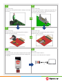
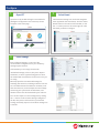
Congure
Open ICT
Open the ICT by double-clicking the executable le
(Intelligent Conguration Tool v2.X.X.exe). The ICT
will open to the Home page
Select Board
Click the Board Settings icon on the left navigation
menu (by default the second item). Click the “Select
Board” button in the center of the window, or click
the “+” at the top next to the “Start Page” tab. Click
the board you wish to congure.
Enter Sengs
Enter all desired settings, or use one of the
recommended congurations for your module by
clicking “Import è Board”.
If the module you are using is listed under
“Predened Settings”, select it, then press “Import”.
Otherwise, it is often a good starting point to select
the module with characteristics closest to the one you
are using.
Microchip provides recommended settings for
switching characteristics, including multi-level turn-on/
turn-o and desaturation waveforms. However, note
that some features, such as temperature and voltage
monitoring, are system-level considerations, and
therefore these must be determined by the end user.
You can also import a custom settings le by clicking
the “…” button under “Custom Settings”. Navigate to
the le, then press “Load from le” to preview the
settings, and nally “Import” to load these settings into
a new tab.
1 2
3

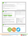
Compile
Click the “Compile” button on the right. Enter any of the optional
traceability information, then click “Compile!” to conrm.
Select a location to save the output. The compilation process will
create a new folder named SOFT-XXXXX-YY (depending on the entered
Part Number) containing all output les. Click “Select Folder” to
continue.
A window displaying compilation progress will appear. Wait for the
process to nish, then click “Close”.
Program
Open MPLAB X IPE. In the “Device” box, enter the
corresponding device based on the board you are
programming, using the table below.
Board Device
2ASC series PIC16F1776
62EM1 series PIC16F1773
Click “Apply”. Make sure PICkit 4 is selected as the Tool, then
click “Connect”.
Next to “Hex File”, click “Browse” and select the SOFT-XXXXX-
YY.hex le generated during compilation. Ensure the driver
board is powered, then click “Program”.
Power to the driver board can be made available through the
IPE software conguration by selecting Advanced Mode in
the Settings Pulldown menu (see right) or from the hardware
platform.
Test
Your board is ready to test! If you wish to change any parameters, simply edit those values in the Board Settings
page and repeat steps 4 and 5.
The Microchip name and logo, the Microchip logo, MPLAB and PIC are registered trademarks of Microchip Technology Incorporated
in the U.S.A. and other countries. Arm and Cortex are registered trademarks of Arm Limited in the EU and other countries. All other
trademarks mentioned herein are property of their respective companies.
© 2022, Microchip Technology Incorporated and its subsidiaries. All Rights Reserved. 3/22 DS00004386B
4
5
6
-
 1
1
-
 2
2
-
 3
3
-
 4
4
-
 5
5
-
 6
6


in altre lingue
- English: MICROCHIP SIC User guide
Altri documenti
-
Gigabyte W480M VISION W Manuale del proprietario
-
Mettler Toledo ICS241- Guida d'installazione
-
Gigabyte W480 VISION W Manuale del proprietario
-
-
-
-
-
-
-