NEC AccuSync LCD22WMGX Manuale del proprietario
- Categoria
- TV
- Tipo
- Manuale del proprietario
Questo manuale è adatto anche per

AccuSync LCD22WMGX
AccuSync LCD24WMCX
User’s Manual
Bedienerhandbuch
Manual del usuario
Manuel Utilisateur
Manuale utente
Руководство пользователя
Kullan∂c∂ Kılavuzu
00_Cover 25/9/07, 12:15 PM1

TCO’06 (LCD24WMCX Only)
Congratulations!
The product you have just purchased carries the TCO’06 Media
Displays label. This means that your display is designed and
manufactured according to some of the strictest performance and
environmental criteria in the world. The manufacturer of this display
has selected it to be certified to TCO’06 Media Displays as a sign of
usability, high performance and reduced impact on the natural
environment.
Products certified to TCO´06 Media Displays are specifically designed for high quality reproduction
of moving images. Features such as luminance, colour rendition and response time are important
when watching TV or working with media, graphics, web design and other applications that demand
outstanding moving images.*
Other features of TCO’06 Media Displays:
Ergonomics
• Good visual ergonomics and image quality in order to reduce vision and strain problems.
Criteria for luminance, contrast, resolution, reflectance, colour rendition and response time.
Energy
• Energy saving mode – beneficial both for the user and the environment
• Electrical safety
Emissions
• Low electromagnetic fields surrounding the display
Ecology
• Product is designed for recycling. Manufacturer must have a certified environmental
management system such as EMAS or ISO 14 001
• Restrictions on:
- Chlorinated and brominated flame retardants and polymers
- Hazardous heavy metals such as cadmium, mercury, hexavalent chromium and lead.
All TCO labelled products are verified and certified by TCO Development, an independent third party
labelling organization. For over 20 years, TCO Development has been at the forefront of moving the
design of IT equipment in a more user-friendly direction. Our criteria are developed in collaboration
with an international group of researchers, experts, users and manufacturers. Since the program’s
inception, TCO labelled products have grown in popularity and are now requested by users and IT-
manufacturers all over the world.
Full specifications and lists of certified products can be found on our homepage
www.tcodevelopment.com
* For a display used primarily for conventional work tasks such as word processing, we recommend a display certified to
our office display series TCO’03 Displays or later version.
00_Cover 25/9/07, 12:15 PM2

Manufacturer’s Recycling and Energy Information
NEC DISPLAY SOLUTIONS is strongly committed to environmental protection and sees recycling
as one of the company’s top priorities in trying to minimize the burden placed on the environment.
We are engaged in developing environmentally-friendly products, and always strive to help define
and comply with the latest independent standards from agencies such as ISO (International
Organisation for Standardization) and TCO (Swedish Trades Union).
Disposing of your old NEC product
The aim of recycling is to gain an environmental benefit by means of re-use, upgrading,
reconditioning or reclamation of material. Dedicated recycling sites ensure that environmentally
harmful components are properly handled and securely disposed. To ensure the best recycling of
our products, NEC DISPLAY SOLUTIONS offers a variety of recycling procedures and gives
advice on how to handle the product in an environmentally sensitive way, once it has reached the
end of its life.
All required information concerning the disposal of the product and country-specific information on
recycling facilities can be found on our following websites:
http://www.nec-display-solutions.com/greencompany/ (in Europe),
http://www.nec-display.com (in Japan) or
http://www.necdisplay.com (in USA).
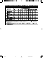
Energy Saving
This monitor features an advanced energy saving capability. When a VESA Display Power
Management Signalling (DPMS) Standard signal is sent to the monitor, the Energy Saving mode is
activated. The monitor enters a single Energy Saving mode.
WEEE Mark (European Directive 2002/96/EC)
Within the European Union
EU-wide legislation, as implemented in each Member State, requires that waste
electrical and electronic products carrying the mark (left) must be disposed of
separately from normal household waste. This includes monitors and electrical
accessories, such as signal cables or power cords. When you need to dispose of
your NEC display products, please follow the guidance of your local authority, or
ask the shop where you purchased the product, or if applicable, follow any
agreements made between yourself and NEC.
The mark on electrical and electronic products only applies to the current European Union Member
States.
Outside the European Union
If you wish to dispose of used electrical and electronic products outside the European Union, please
contact your local authority so as to comply with the correct disposal method.
Mode Power consumption LED color
Normal Operation Approx. 48W (LCD22WMGX) Blue
Approx. 98W (LCD24WMCX)
Energy Saving Mode Less than 2W Amber
Off Mode Less than 1W Unlit
00_Cover 25/9/07, 12:15 PM3

Chinese RoHS-information relevant for Chinese market
00_Cover 25/9/07, 12:15 PM4

English-1
English
Declaration of the Manufacturer
We hereby certify that the colour monitors AccuSync LCD22WMGX
(TFT22W90PS)/AccuSync LCD24WMCX (TFT24W90PS) are in
compliance with
RISK OF ELECTRIC SHOCK • DO NOT OPEN
TO PREVENT FIRE OR SHOCK HAZARDS, DO NOT EXPOSE THIS UNIT TO RAIN OR MOISTURE. ALSO, DO NOT USE THIS UNIT’S
POLARIZED PLUG WITH AN EXTENSION CORD RECEPTACLE OR OTHER OUTLETS UNLESS THE PRONGS CAN BE FULLY INSERTED.
REFRAIN FROM OPENING THE CABINET AS THERE ARE HIGH VOLTAGE COMPONENTS INSIDE. REFER SERVICING TO QUALIFIED
SERVICE PERSONNEL.
WARNING
CAUTION: TO REDUCE THE RISK OF ELECTRIC SHOCK,
DO NOT REMOVE COVER (OR BACK). NO USER
SERVICEABLE PARTS INSIDE. REFER SERVICING
TO QUALIFIED SERVICE PERSONNEL.
This symbol warns user that uninsulated voltage
within the unit may have sufficient magnitude to cause
electric shock. Therefore, it is dangerous to make any
kind of contact with any part inside this unit.
This symbol alerts the user that important literature
concerning the operation and maintenance of this
unit has been included. Therefore, it should be read
carefully in order to avoid any problems.
CAUTION
and marked with
NEC Display Solutions, Ltd.
4-13-23, Shibaura,
Minato-Ku
Tokyo 108-0023, Japan
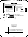
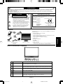
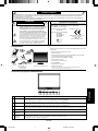
Contents
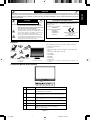
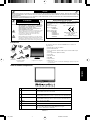
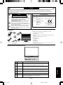
Your new NEC LCD monitor box* should contain the following:
• LCD monitor with tilt base
• Power Cord
•Video Signal Cable (15-pin mini D-SUB to 15-pin mini D-SUB
male)
•Video Signal Cable (DVI-D to DVI-D)
• Audio Cable
• User’s Manual
• CD-ROM
• Base Stand
• Cable Holder
*
Remember to save your original box and packing material to transport or ship
the monitor.
User’s Manual
Power Cord
15-pin mini D-SUB
to 15-pin mini
D-SUB male
Cable
Holder
LCD monitor
(Stand not connected)
CD-ROM
Council Directive 73/23/EEC:
– EN 60950-1
Council Directive 89/336/EEC:
– EN 55022
– EN 61000-3-2
– EN 61000-3-3
– EN 55024
Audio Cable
DVI-D to DVI-D
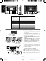
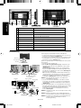
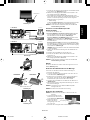
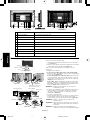
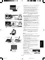
1
2
3
4
5
6
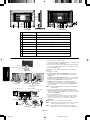
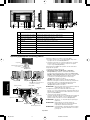
7
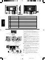
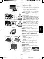
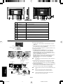
Source
Auto
-/<
+/>
Menu
Power Switch
Power LED
Switches the input source being displayed.
When not in OSD menu, enables Auto Configuration.
When in OSD menu, act EXIT-key.
When not in OSD menu, lowers the sound volume.
When in OSD menu, decreases value or move left/up cursor.
When not in OSD menu, raises the sound volume.
When in OSD menu, increases value or move right/down cursor.
Opens or Closes the OSD menu.
Turns on or off the main power.
LED Blue - Power is ON.
LED Amber - Monitor is in “Power Saving Mode”.
LED is off - Power is OFF.
Component Names and Functions
01_English 25/9/07, 12:15 PM1

English-2
English
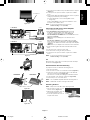
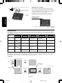
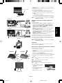
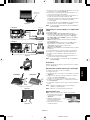
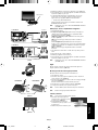
Figure B.1
Cable holder
Input (DVI)
Audio Cable
Input (VGA)
Power Cable
Quick Start
To attach the Base to the LCD Stand:
1. Insert the front of the LCD stand into the holes in the front of the
Base (Figure S.1).
2. Attach the Base to the Stand. The locking tab on the Base should
fit into the hole on the back of the Stand (Figure S.1).
To attach the LCD monitor to your system, follow these instructions:
1. Turn off the power to your computer.
2. For the PC or MAC with DVI digital output: Connect the DVI
signal cable to the connector of the display card in your system
(Figure A.1).
For the PC with Analog output: Connect the 15-pin mini D-SUB
signal cable connected with the monitor to the connector of the
display card in your system (Figure A.2). Tighten all screws.
For the Mac: Connect the MultiSync Macintosh cable adapter
(not included) to the computer. Attach the 15-pin mini D-SUB
signal cable to the MultiSync Macintosh cable adapter
(Figure A.3). Tighten all screws.
NOTE: Some Macintosh systems do not require a Macintosh cable
adapter.
3. Connect one end of the power cord to the monitor and the other
end to the power outlet. Use the Cable holder to keep the Video
Signal Cable, Audio cable and power cord together (Figure B.1).
4. To attach the Cable Holder:
Attach the Cable Holder on to the Base. Insert the hooks on the
Cable Holder into the holes at the back of the Stand and slide the
Cable Holder downward into place (Figure B.1).
NOTE: Please confirm that the tabs are completely secure.
NOTE: Adjust position of cable that place under the Cable holder to
avoid damage for cable or monitor.
NOTE: Please refer to Caution section of this manual for proper
selection of power cord.
Figure S.1
Figure A.1 Figure A.2
Stand
Base
Locking Tabs
Macintosh Cable Adapter
(not included)
LCD22WMGX LCD24WMCX
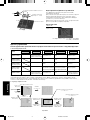
1
2
3
4
5
6
7
8
9
10
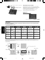
SPDIF OUT
Component (Audio)
Component (Video)
Headphone Jack
AUDIO IN
D-SUB
DVI-D
HDMI
AC IN
Kensington Lock Opening
Outputs the Digital audio signal from HDMI (COAXIAL).
Connects Component Audio.
Connects Component Video.
Connects headphones to the monitor.
Connects audio input from PC.
Connects to analog RGB input.
Connects to digital RGB input.
Connects to digital HDMI signals.
Connects power cord to monitor.
Monitor can be secured using a Kensington locking system.
Figure A.3
Input (HDMI)
Headphone
01_English 25/9/07, 12:15 PM2

English-3
English
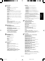
Figure C.1
Power Button
Figure TS.1
Figure R.1
Non-abrasive surface
Figure R.2
Tab
5. Turn on the monitor with the front power button and the computer
(Figure C.1).
6. Select input source by Source button or Input Select on OSD
menu.
7. No-touch Auto Adjust automatically adjusts the monitor to optimal
settings upon initial setup for most timings.
For further adjustments, use the following OSD controls:
• Image Setup
Refer to the Controls section of this User’s Manual for a full
description of these OSD controls.
NOTE: If you have any problem, please refer to the
Troubleshooting section (CD-ROM).
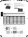
Connecting to DVD player, Stereo Amplifier
1. Turn off the power to the monitor.
2. For the DVD player with component out: Connect the
Component connecter (RCA) on the LCD monitor, use a
separately available RCA connector cable (Figure D).
For the DVD Player with HDMI out: Connect HDMI cable to the
DVD player (Figure D).
NOTE: Refer to your DVD player user’s manual for more
information.
For the Stereo Amplifier: Connect HDMI cable to the DVD
player. Connect the stereo RCA cable to the SPDIF (COAXIAL)
connector on the LCD monitor and the audio input on the amplifier
(Figure D).
NOTE: Refer to your amplifier user’s manual for more information.
3. Keep all cables together and attach the Cable Holder into the
Base.
4. Connect the power cord to the power outlet.
5. Turn the monitor on using the front power button.
6. Select input source by Source button or Input Select on OSD
menu.
NOTE: If you have any problem, please refer to the
Troubleshooting section (CD-ROM).
Tilt
Grasp both sides of the monitor screen with your hands and adjust
the tilt as desired (Figure TS.1).
Remove Monitor Stand for Mounting
To prepare the monitor for alternative mounting purposes:
1. Disconnect all cables.
2. Place monitor face down on a non-abrasive surface (Figure R.1).
3. Remove the 3 screws connecting the monitor to the stand and
remove the stand as indicated (Figure R.1).
The monitor is now ready for mounting in an alternative manner.
4. Connect the AC cord to the back of the monitor (Figure R.2).
5. Reverse this process to re-attach stand.
NOTE: Use only VESA-compatible alternative mounting method.
NOTE: Handle with care when removing monitor stand.
Removing the Base
NOTE: Always remove the Base when shipping the LCD.
1. Place monitor face down on a non-
abrasive surface (Figure R.1).
2. While using your thumbs, press the
bottom tabs upward to unlock.
3. Press the top tabs down to unlock
and pull off the stand.
HDMI Connector
RCA
RCA
To Audio
From HDMI Output
DVD
External Speakers
Amplifier
Left Audio
Right Audio
RCA
Figure D
LCD22WMGX
From HDMI Output
Left Audio
Right Audio
RCA
LCD24WMCX
DVD
External Speakers
Amplifier
HDMI Connector
RCA
RCA
To Audio
LCD22WMGX LCD24WMCX
01_English 25/9/07, 12:15 PM3

English-4
English
2. OSD Lock function
To lock the OSD, press and hold the MENU button while the monitor is off and then press power button to turn the monitor on. To un-lock the
OSD press and hold the MENU button while the monitor is off and then press power button to turn the monitor on.
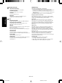
3. OSD structure
Controls
OSD (On-Screen Display) control buttons on the front of the monitor function as follows:
1. Basic Key function
Main menu selection stage
Main menu selection stage
Press
“MENU” key
Press
“- / <” or “+ / >”
Press
“AUTO” key
Press
“MENU” key
Adjust by using
“- / <” or “+ / >”
Press
“AUTO” key
Press
“AUTO” key
Press
“MENU” key
Press
“AUTO” or “MENU”
key
Adjustment stage
Press
“- / <” or “+ / >”
Active Auto Adjustment
function (Press over
2 seconds)
Shortcut to volume
window
Button
OSD Off Shortcut to volume
window
OSD ON
(Main menu selection
stage)
Act Exit-key Cursor moves up Cursor moves down
OSD ON
(Sub menu selection
stage)
Act Exit-key Cursor moves up Cursor moves down
AUTO
– / < + / >
OSD displayed
Go to Adjustment stage
MENU
OSD Lock Active Auto Adjustment
function (Press over
2 seconds)
Shortcut to volume
window
Shortcut to volume
window
Message displayed
“OSD Loked”
Go to Sub menu
selection stage
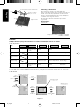
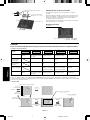
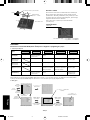
Connecting a Flexible Arm
This LCD monitor is designed for use with a flexible arm.
Please use the attached screws (4pcs) as shown in the picture when
installing. To meet the safety requirements, the monitor must be
mounted to an arm which guaranties the necessary stability under
consideration of the weight of the monitor.
The LCD monitor shall only be used with an approved arm
(e.g. GS mark).
4-SCREWS (M4)
(MAX depth: 10 mm)
Weight of LCD assembly: 5.0 kg (MAX) - LCD22WMGX
7.0 kg (MAX) - LCD24WMCX
Specifications
4 x 12 mm with lock washer and flat washer
Tighten all screws
100 mm
100 mm
Thickness of Bracket
(Arm) 2.0 ~ 3.2 mm
12 mm
M4
SOURCE
Select Signal
OSD ON
(Adjustment stage)
Act Exit-key Adjust value decrease
or Cursor for adjust
moves left
Adjust value increase or
Cursor for adjust moves
right
Go to Sub menu
selection stage
Select Signal
Sub menu selection stage
Select Item by using
“- / <” or “+ / >”
OSD off
01_English 25/9/07, 12:15 PM4

English-5
English
Luminance
Contrast
Contrast from Digital-register.
Brightness
Backlight Adjustment.
DV Mode
Adjusts picture as following.
Standard: Brightness = 90, Contrast = 50 (adjustable)
Text: Brightness = 20, Contrast = 80 (nonadjustable)
Internet: Brightness = 40, Contrast = 80 (nonadjustable)
Game: Brightness = 60, Contrast = 80 (nonadjustable)
Movie: Brightness = 80, Contrast = 80 (nonadjustable)
Sports: Brightness = 100, Contrast = 80 (nonadjustable)
Gamma
Gamma Adjustment.
DCR
Dynamic contrast ratio.
Note: When DCR is not supported Contrast, Brightness,
DV Mode and GAMMA.
When DCR/Color Boost/Picture Boost recalls Color Temp.
The Contrast is not smaller than 2000 to 1.
Image Setup
Clock (no DVI support)
Adjusts picture Clock to reduce Vertical-Line noise.
Focus (no DVI support)
Adjusts Picture Phase to reduce Horizontal-Line noise.
H. Position (no DVI support)
Adjusts the horizontal position of the picture.
V. Position (no DVI support)
Adjusts the vertical position of the picture.
Audio Control
Volume
Adjusts the volume of the audio.
Balance
Adjusts the Balance of the audio.
Bass
Adjusts the Bass of the audio.
Treble
Adjusts the Treble of the audio.
Color Temp.
Normal
Recalls Normal Color Temperature.
(RGB value is non-adjustable).
Warm
Recalls Warm Color Temperature.
(RGB value is non-adjustable).
Cool
Recalls Cool Color Temperature.
(RGB value is non-adjustable).
sRGB (for the model with sRGB function)
Recalls sRGB Color Temperature from.
(RGB value is non-adjustable).
User
Adjusts R, G, B, Y, C and M as desired.
User-R
Red Gain from Digital-register.
User-G
Green Gain from Digital-register.
User-B
Blue Gain from Digital-register.
User-Y
Red/Green Gain from Digital-register.
User-C
Green/Blue Gain from Digital-register.
User-M
Red/Blue Gain from Digital-register.
Note: When some item of DCR/Color Boost/Picture Boost is
set to ON, then user adjusts color temp, the screen display
effect will change along with the color temp adjustment if
users turn off some item which DCR/Color Boost/Picture
Boost is set on previous.
When Normal, Warm or Cool is selected, contrast/brightness
are reset.
Color Boost (Alternative)
Full Enhance
Full Enhance.
Nature Skin
Red Gain from Digital-register.
Green Field
Green Gain from Digital-register.
Sky-Blue
Blue Gain from Digital-register.
Auto Detect
Auto gain for input signal.
Demo
Enhances Area in half Picture.
Whether DEMO on or off, it is effected Full Enhance, Nature-
Skin, Green-Field, Sky-blue, Auto Detect displays in the left
side screen.
Picture Boost
Frame Size (When Bright Frame is ON)
Adjusts the Size of the Frame.
Note: The smallest size is 14.
Brightness (When Bright Frame is ON)
Brightness Adjustment for Enhance Area.
Contrast (When Bright Frame is ON)
Contrast Adjustment for Enhance Area.
Hue (When Bright Frame is ON)
Hue Adjustment for Enhance Area.
Saturation (When Bright Frame is ON)
Saturation Adjustment for Enhance Area.
Position (When Bright Frame is ON)
Adjusts the horizontal position of the Frame.
Adjusts the vertical position of the Frame.
Bright Frame
Enhances Area function.
Note: After Bright frame turns OFF to ON, the values of
Frame Size recalls factory mode.
Bright Frame and the Frame Size do not store the position
setting.
01_English 25/9/07, 12:15 PM5

English-6
English
OSD Setup
H. Position
Adjusts the horizontal position of the OSD.
V. Position
Adjusts the vertical position of the OSD.
Timeout
Adjusts the OSD timeout.
Language
Sets OSD display language to English.
(English is the default setting).
Extra
Input Select
Selects input source Ypbpr and HDMI for MFM.
Auto Adjust
Auto Adjusts the H/V Position, Focus and Clock of picture.
DDC/CI
Turns on or off the two-way communication between the
graphics card and the monitor.
With DDC/CI turned on, some monitor settings
can be adjusted through the graphics card using
a computer.
Reset
Clears each old status of Auto-configuration and sets the
color temperature to Warm and recall.
Aspect
Sets up the rate of showing.
Information
Shows the resolution, H/V frequency, serial number and input
port of current input timing.
OSD Message:
Auto Config Please Wait
1. When Analog signal input, if User Press Hot-Key “Auto”, will show
this message, and the monitor do the auto configuration function.
This message location is at the position setting in “OSD Setup”
item.
2. When Digital signal input, without this OSD Message.
Input Not Support
When the Hsync Frequency, Vsync Frequency or Resolution is out of
the monitor support range, will show this message. This message will
be flying.
No Signal
When the video cable is not connected, or the video cable is
connected but there is no active signal input, will show this message,
after 9s the monitor will enter power saving. This message location is
at the position setting in “OSD Setup” item.
OSD Locked
When the OSD is unlocked, keep holding down “Menu” key and
“Power” key once to turn on the monitor, the OSD will be locked and
show this message. When the OSD is locked, only Power key
function is still working, if user press other key will also this message.
When the OSD is locked, keep holding down “Menu” key and press
“Power” key once to turn on the monitor, the OSD will be unlocked an
does not show message. This message location is at the position
setting in “OSD Setup” item.
Input Signal
1. D-SUB: Analog PC source is selected.
2. DVI: Digital PC source is selected.
3. Ypbpr: Analog Video source (Component) is selected.
4. HDMI: Digital Video source (HDMI) is selected.
01_English 25/9/07, 12:15 PM6

Deutsch-1
Deutsch
STROMSCHLAGGEFAHR • NICHT ÖFFNEN
SETZEN SIE DAS GERÄT WEDER REGEN NOCH FEUCHTIGKEIT AUS, DA ES ANDERNFALLS ZU FEUER ODER STROMSCHLÄGEN KOMMEN
KANN. VERWENDEN SIE DEN NETZSTECKER DIESES GERÄTS KEINESFALLS MIT EINEM VERLÄNGERSKABEL ODER EINER
STECKDOSENLEISTE, WENN DIE STECKERSTIFTE NICHT VOLLSTÄNDIG EINGEFÜHRT WERDEN KÖNNEN.
ÖFFNEN SIE DAS GEHÄUSE NICHT, DA SICH IM INNEREN KOMPONENTEN BEFINDEN, DIE UNTER HOCHSPANNUNG STEHEN. LASSEN SIE
WARTUNGSARBEITEN VON QUALIFIZIERTEN WARTUNGSTECHNIKERN DURCHFÜHREN.
WARNUNG
VORSICHT: ENTFERNEN SIE KEINESFALLS ABDECKUNG ODER
RÜCKSEITE, DAMIT ES NICHT ZU STROMSCHLÄGEN
KOMMT. IM INNEREN BEFINDEN SICH KEINE VOM
BENUTZER ZU WARTENDEN KOMPONENTEN. LASSEN
SIE WARTUNGSARBEITEN VON QUALIFIZIERTEN
WARTUNGSTECHNIKERN DURCHFÜHREN.
Dieses Symbol weist den Benutzer auf nicht isolierte
spannungsführende Komponenten im Gerät hin, die
Stromschläge verursachen können. Aus diesem Grund
dürfen Sie keinesfalls Kontakt mit einer Komponente im
Geräteinneren herstellen.
Dieses Symbol weist den Benutzer auf wichtige
Informationen zu Betrieb und Pflege dieses Geräts hin.
Die Informationen sollten sorgfältig gelesen werden, um
Probleme zu vermeiden.
VORSICHT
Erklärung des Herstellers
Wir bestätigen hiermit, dass die Farbmonitore AccuSync
LCD22WMGX (TFT22W90PS) und AccuSync LCD24WMCX
(TFT24W90PS) folgenden Richtlinien entsprechen:
und mit folgendem Siegel
gekennzeichnet ist:
NEC Display Solutions, Ltd.
4-13-23, Shibaura,
Minato-Ku
Tokyo 108-0023, Japan
EG-Direktive 73/23/EG:
– EN 60950-1
EG-Direktive 89/336/EG:
– EN 55022
– EN 61000-3-2
– EN 61000-3-3
– EN 55024
Inhalt der Verpackung
Der Karton* mit Ihrem neuen NEC LCD-Monitor sollte folgende
Komponenten enthalten:
• LCD-Monitor mit verstellbarem Fuß
• Netzkabel
• Signalkabel (15-poliger Mini-D-SUB-Stecker mit 15 Stiften an
beiden Seiten)
• Signalkabel (DVI-D auf DVI-D)
• Audiokabel
• Bedienungsanleitung
• CD-ROM
• Standfuß
• Kabelhalter
*
Bewahren Sie den Originalkarton und das Verpackungsmaterial für spätere
Transporte des Monitors auf.
Bedienung-
sanleitung
Netzkabel
15-poliger Mini-D-
SUB-Stecker mit
15 Stiften an beiden
Seiten
Kabelhalter
LCD-Monitor
(Fuß nicht montiert)
CD-ROM
Audiokabel
DVI-D auf DVI-D
Komponenten und ihre Funktionen
1
2
3
4
5
6
7
Quelle
Auto
-/<
+/>
Menü
Netzschalter
Strom-LED
Wechselt die angezeigte Eingangsquelle.
Wenn Sie nicht im OSD-Menü sind, wird so die automatische Einstellung aktiviert.
Wenn Sie im OSD-Menü sind, verlassen Sie das Menü, wenn Sie diese Taste drücken.
Wenn Sie nicht im OSD-Menü sind, wird so die Lautstärke gesenkt.
Wenn Sie im OSD-Menü sind, wird so der Wert gesenkt oder der Cursor nach links/oben bewegt.
Wenn Sie nicht im OSD-Menü sind, wird so die Lautstärke erhöht.
Wenn Sie im OSD-Menü sind, wird so der Wert erhöht oder der Cursor nach rechts/unten bewegt.
Öffnet oder schließt das OSD-Menü.
Schaltet die Stromversorgung ein oder aus.
LED blau – Monitor ist EINGESCHALTET.
LED gelb – Monitor ist im „Energiesparmodus“.
LED aus – Monitor ist AUSGESCHALTET.
02_German 25/9/07, 12:15 PM1

Deutsch-2
Deutsch
Kurzanleitung
So befestigen Sie den Standfuß am Fuß des LCD-Monitors:
1. Setzen Sie die Vorderseite des LCD-Fußes in die Löcher auf der
Vorderseite des Standfußes (Abbildung S.1).
2. Befestigen Sie den Standfuß am Monitor. Der Schnappverschluss
des Standfußes muss in die Aussparung auf der Rückseite des
Monitorfußes einrasten (Abbildung S.1).
Gehen Sie folgendermaßen vor, um den LCD-Monitor an Ihr System
anzuschließen:
1. Schalten Sie Ihren Computer aus.
2. PC oder Mac mit digitalem DVI-Ausgang: Verbinden Sie das
DVI-Kabel mit dem Anschluss der Grafikkarte in Ihrem System
(Abbildung A.1).
PC mit analogem Ausgang: Verbinden Sie den Mini-D-SUB-
Stecker (15 Stifte) des am Monitor montierten Signalkabels mit
dem Anschluss der Grafikkarte in Ihrem System (Abbildung A.2).
Ziehen Sie die Schrauben fest.
Mac: Schließen Sie den MultiSync-Kabeladapter für Macintosh
(nicht mitgeliefert) an den Computer an. Stecken Sie den Mini-D-
SUB-Stecker (15 Stifte) des Signalkabels in den Macintosh-
Kabeladapter (Abbildung A.3). Ziehen Sie die Schrauben fest.
HINWEIS: Für einige Macintosh-Systeme ist kein Macintosh-
Kabeladapter erforderlich.
3. Stecken Sie ein Ende des Netzkabels in den Monitor und das
andere Ende in die Steckdose. Verwenden Sie den Kabelhalter,
um Signalkabel, Audiokabel und Netzkabel zusammenzuhalten
(Abbildung B.1).
4. Gehen Sie folgendermaßen vor, um den Kabelhalter zu befestigen:
Befestigen Sie den Kabelhalter am Standfuß. Stecken Sie die Haken
des Kabelhalters in die Aussparungen auf der Rückseite des
Monitorfußes und schieben Sie den Kabelhalter nach unten in
Position (Abbildung B.1).
HINWEIS: Überprüfen Sie bitte, dass der Schnappverschluss richtig
eingerastet ist.
HINWEIS: Bringen Sie die Kabel so unter der Kabelabdeckung an,
dass weder Kabel noch Monitor beschädigt werden können.
HINWEIS: Beachten Sie zur Auswahl des richtigen Netzkabels den
entsprechenden Sicherheitshinweis in dieser
Bedienungsanleitung.
Abbildung S.1
Monitorfuß
Standfuß
Verriegelungen
LCD22WMGX LCD24WMCX
Abbildung B.1
Kabelhalter
Eingang (DVI)
Audiokabel
Eingang (VGA)
Netzkabel
Abbildung A.1 Abbildung A.2
Macintosh-Kabeladapter
(nicht mitgeliefert)
Abbildung A.3
Eingang (HDMI)
Kopfhörer
1
2
3
4
5
6
7
8
9
10
SPDIF OUT
Komponente (Audio)
Komponente (Video)
Kopfhörerbuchse
AUDIO IN
D-SUB
DVI-D
HDMI
Wechselstrom (Eingang)
Öffnung für Kensington-Schloss
Ausgabe für das digitale Audiosignal von HDMI (KOAXIAL).
Verbindet die Audiokomponente.
Verbindet die Videokomponente.
Verbindet die Kopfhörer mit dem Monitor.
Verbindet den Audioeingang des PCs.
Verbindet den analogen RGB-Eingang.
Verbindet den digitalen RGB-Eingang.
Verbindet zu den digitalen HDMI-Signalen.
Verbindet das Netzkabel mit dem Monitor.
Der Monitor kann mithilfe eines Kensington-Schlosses gesichert werden.
02_German 25/9/07, 12:15 PM2

Deutsch-3
Deutsch
Verriegelungen
5. Schalten Sie den Computer und den Monitor mit dem Netzschalter
an der Vorderseite (Abbildung C.1) ein.
6. Wählen Sie die Eingangsquelle mithilfe der Taste „Quelle“ oder
über „Eingangsauswahl“ im OSD-Menü.
7. Die berührungslose Einstellungsautomatik nimmt beim ersten
Setup für die meisten Timings die optimalen Einstellungen für den
Monitor vor. Weitere Anpassungen werden mit den folgenden
OSD Steuerungen vorgenommen:
• Bildeinstellung
Im Abschnitt Bedienelemente dieser Bedienungsanleitung finden
Sie eine ausführliche Beschreibung der OSD-Steuerungen.
HINWEIS: Sollten Probleme auftreten, beachten Sie den Abschnitt
Fehlerbehebung (CD-ROM).
Anschluss an einen DVD-Player oder
Stereoverstärker
1. Schalten Sie den Monitor aus.
2. Bei einem DVD-Player mit Komponentenausgang: Verbinden
Sie den RCA-Anschluss über ein getrennt erhältliches RCA-
Anschlusskabel mit dem LCD-Monitor (Abbildung D).
Bei einem DVD-Player mit HDMI-Ausgang: Schließen Sie das
HDMI-Kabel an den DVD-Player an (Abbildung D).
HINWEIS: Weitere Informationen finden Sie im Benutzerhandbuch
Ihres DVD-Players.
Bei einem Stereoverstärker: Schließen Sie das HDMI-Kabel an
den DVD-Player an. Schließen Sie das RCA-Kabel an den SPDIF-
Anschluss (KOAXIAL) am LCD-Monitor und an den Audioeingang
am Verstärker an (Abbildung D).
HINWEIS: Weitere Informationen finden Sie im Benutzerhandbuch
zu Ihrem Verstärker.
3. Nehmen Sie alle Kabel und befestigen Sie den Kabelhalter am
Standfuß.
4. Schließen Sie das Netzkabel an die Steckdose an.
5. Schalten Sie den Monitor über die Einschalttaste auf der
Vorderseite ein.
6. Wählen Sie die Eingangsquelle mithilfe der Taste „Quelle“ oder
über „Eingangsauswahl“ im OSD-Menü.
HINWEIS: Sollten Probleme auftreten, beachten Sie den Abschnitt
Fehlerbehebung (CD-ROM).
Neigen
Fassen Sie den Monitor an beiden Seiten und neigen Sie ihn nach
Bedarf (Abbildung TS.1).
Entfernen des Monitorfußes für die Montage
So bereiten Sie den Monitor für eine alternative Montage vor:
1. Ziehen Sie alle Kabel ab.
2. Legen Sie den Monitor mit der Vorderseite nach unten auf eine
weiche Oberfläche (Abbildung R.1).
3. Entfernen Sie die 3 Schrauben, mit denen der Fuß am Monitor
befestigt ist, und heben Sie den Fuß ab (Abbildung R.1).
Der Monitor kann jetzt auf andere Art montiert werden.
4. Schließen Sie das Netzkabel an der Rückseite des Monitors an
(Abbildung R.2).
5. Führen Sie die Schritte in umgekehrter Reihenfolge aus, um den
Fuß wieder anzubringen.
HINWEIS: Verwenden Sie ausschließlich VESA-kompatible
Montagemethoden.
HINWEIS: Entfernen Sie den Monitorfuß vorsichtig.
Entfernen des Standfußes
HINWEIS: Entfernen Sie den Standfuß vor dem Versenden des
Monitors.
1. Legen Sie den Monitor mit der
Vorderseite nach unten auf eine
weiche Oberfläche (Abbildung R.1).
2. Drücken Sie mit den
Daumen die unteren
Verriegelungen nach oben,
um sie zu lösen.
3. Ziehen Sie den entriegelten Fuß vom Monitor ab.
Abbildung C.1
Netzschalter
Abbildung TS.1
Abbildung R.1
Weiche Oberfläche
Abbildung R.2
HDMI-Anschluss
RCA
RCA
An Audio
Von HDMI-Ausgang
DVD
Externe
Lautsprecher
Verstärker
Linker Audioausgang
Rechter Audioausgang
RCA
Abbildung D
LCD22WMGX
Von HDMI-Ausgang
Linker Audioausgang
Rechter Audioausgang
RCA
LCD24WMCX
DVD
Externe
Lautsprecher
Verstärker
HDMI-Anschluss
RCA
RCA
An Audio
LCD22WMGX LCD24WMCX
02_German 25/9/07, 12:15 PM3

Deutsch-4
Deutsch
2. OSD-Sperrfunktion
Um die OSD-Anzeige zu sperren, drücken Sie die MENU-Taste und halten Sie diese gedrückt, während der Monitor ausgeschaltet ist. Schalten
Sie den Monitor anschließend wieder ein. Um die OSD-Anzeige zu entsperren, drücken Sie die MENU-Taste und halten Sie diese gedrückt,
während der Monitor ausgeschaltet ist. Schalten Sie den Monitor anschließend wieder ein.
3. OSD-Struktur
Bedienelemente
Die OSD-Bedienelemente (On-Screen-Display) auf der Vorderseite des Monitors haben folgende Funktionen:
1. Grundfunktionen der Tasten
Hauptmenüauswahlmodus
Hauptmenüauswahlmodus
Taste „MENU“
drücken
Taste
„- / <“ oder „+ / >“
drücken
Taste „AUTO“
drücken
Taste „MENU“
drücken
Mit
„- / <“ oder „+ / >“ anpassen
Taste „AUTO“
drücken
Taste „AUTO“
drücken
Taste „MENU“
drücken
Taste „AUTO“ oder
„MENU“ drücken
Einstellungsmodus
Taste „- / <“ oder „+ / >“
drücken
Aktiv - Automatische
Einstellung (länger als 2
Sekunden gedrückt halten)
Öffnet das
Fenster für die
Lautstärkeeinstellung
Taste
OSD Off Öffnet das
Fenster für die
Lautstärkeeinstellung
OSD ON
(Hauptmenüauswahlmodus)
Akt. Exit-Taste Cursor bewegt sich
nach oben
Cursor bewegt sich
nach unten
OSD ON
(Untermenüauswahlmodus)
Akt. Exit-Taste Cursor bewegt sich
nach oben
Cursor bewegt sich
nach unten
AUTO
– / < + / >
OSD wird angezeigt
Wechselt zum
Einstellungsmodus
MENU
OSD-Sperre
Aktiv - Automatische
Einstellung (länger als 2
Sekunden gedrückt halten)
Öffnet das
Fenster für die
Lautstärkeeinstellung
Öffnet das
Fenster für die
Lautstärkeeinstellung
Meldung „OSD
gesperrt“ wird angezeigt
Wechselt zum
Untermenüauswahlmodus
Befestigen eines Tragarms
Dieser LCD-Monitor kann mit einem Tragarm verwendet werden.
Verwenden Sie die beigefügten Schrauben (4 Stück) für die Montage,
wie es in der Abbildung dargestellt ist. Die Sicherheitsvorschriften
verlangen, dass der Monitor an einem Tragarm montiert wird, der für
das Gewicht des Monitors ausreichend stabil ist.
Der LCD-Monitor darf nur auf einem zugelassenen Arm montiert
werden, der beispielsweise mit einem GS-Zeichen versehen ist.
4 SCHRAUBEN (M4)
(maximale Tiefe: 10 mm)
Gewicht des LCD-Monitors komplett: 5,0 kg (max.) - LCD22WMGX
7,0 kg (max.) - LCD24WMCX
Technische Daten
4 x 12 mm mit Federring und Federscheibe
Alle Schrauben
festziehen
100 mm
100 mm
Stärke der Halterung
(Arm) 2,0 ~ 3,2 mm
12 mm
M4
SOURCE
Signal wählen
OSD ON
(Einstellungsmodus)
Akt. Exit-Taste Verringert den Wert
oder bewegt Cursor
nach links
Erhöht den Wert oder
bewegt Cursor nach
rechts
Wechselt zum
Untermenüauswahlmodus
Signal wählen
Untermenüauswahlmodus
Menüpunkt mit
„- / <“ oder „+ / >“
auswählen
OSD Off
02_German 25/9/07, 12:15 PM4

Deutsch-5
Deutsch
Lumineszenz
Kontrast
Stellt den Kontrast aus dem Digitalregister ein.
Helligkeit
Stellt die Hintergrundbeleuchtung ein.
DV Mode
Passt das Bild wie folgt an:
Standard: Helligkeit = 90, Kontrast = 50 (kann angepasst
werden)
Text: Helligkeit = 20, Kontrast = 80 (kann nicht angepasst
werden)
Internet: Helligkeit = 40, Kontrast = 80 (kann nicht angepasst
werden)
Spiel: Helligkeit = 60, Kontrast = 80 (kann nicht angepasst
werden)
Film: Helligkeit = 80, Kontrast = 80 (kann nicht angepasst
werden)
Sport: Helligkeit = 100, Kontrast = 80 (kann nicht angepasst
werden)
Gamma
Gammaeinstellung.
DCR
Dynamisches Kontrastverhältnis.
Hinweis: Ohne DCR-Unterstützung: Kontrast, Helligkeit,
DV Mode und GAMMA.
Wenn DCR/Color Boost/Picture Boost die Farbtemperatur
abruft, ist der Kontrast nicht geringer als 2000 zu 1.
Bildeinstellung
Takt (kein DVI-Signal)
Passt die Bildtaktrate zur Reduzierung des Rauschens
vertikaler Linien an.
Bildschärfe (kein DVI-Signal)
Passt die Bildtaktrate zur Reduzierung des Rauschens
horizontaler Linien an.
Horiz. Position (kein DVI-Signal)
Passt die horizontale Position des Bilds an.
V. Position (kein DVI-Signal)
Passt die vertikale Position des Bilds an.
Audiobedienelemente
Lautstärke
Passt die Audiolautstärke an.
Balance
Passt die Audiobalance an.
Bässe
Passt den Audiobass an.
Höhen
Passt die Audiohöhen an.
Farbtemperatur
Normal
Ruft die normale Farbtemperatur ab.
(Der RGB-Wert kann nicht angepasst werden).
Warm
Ruft die warme Farbtemperatur ab.
(Der RGB-Wert kann nicht angepasst werden).
Kühl
Ruft die kühle Farbtemperatur ab.
(Der RGB-Wert kann nicht angepasst werden).
sRGB (für Modelle mit sRGB-Funktion)
Ruft die Farbtemperatur „sRGB“ ab.
(Der RGB-Wert kann nicht angepasst werden).
Benutzer
Passt R, G, B, Y, C und M wie gewünscht an.
Benutzer-R
Stellt den Rotanteil aus dem Digitalregister ein.
Benutzer-G
Stellt den Grünanteil aus dem Digitalregister ein.
Benutzer-B
Stellt den Blauanteil aus dem Digitalregister ein.
Benutzer-Y
Stellt den Rot-/Grünanteil aus dem Digitalregister ein.
Benutzer-C
Stellt den Grün-/Blauanteil aus dem Digitalregister ein.
Benutzer-M
Stellt den Rot-/Blauanteil aus dem Digitalregister ein.
Hinweis: Wenn einige der Menüpunkte unter DCR/Color
Boost/Picture Boost EINGESCHALTET sind und der Benutzer
die Farbtemperatur anpasst, ändert sich die
Bildschirmanzeige zusammen mit der Einstellung der
Farbtemperatur, wenn der Benutzer einige der
voreingestellten Menüpunkte unter DCR/Color Boost/Picture
Boost ausschaltet.
Wenn „Normal“, „Warm“ oder „Kühl“ ausgewählt wird, werden
Kontrast und Helligkeit zurückgesetzt.
Color Boost (Alternative)
Vollständige Verbesserung
Vollständige Verbesserung.
Natürliche Hautfarbe
Stellt den Rotanteil aus dem Digitalregister ein.
Grünes Feld
Stellt den Grünanteil aus dem Digitalregister ein.
Himmelblau
Stellt den Blauanteil aus dem Digitalregister ein.
Automatische Erkennung
Automatische Erkennung des Eingangssignals.
Demo
Verbessert die Hälfte des Bildes.
Ob DEMO ein- oder ausgeschaltet ist, wirkt sich auf die
Anzeigen „Vollständige Verbesserung“, „Natürliche
Hautfarbe“, „Grünes Feld“, „Himmelblau“ oder „Automatische
Erkennung“ auf der linken Bildschirmseite aus.
Picture Boost
Rahmengröße (wenn „Heller Rahmen“
EINGESCHALTET ist)
Passt die Rahmengröße an.
Hinweis: Die kleinste Größe ist 14.
Helligkeit (wenn „Heller Rahmen“
EINGESCHALTET ist)
Helligkeitseinstellung für den zu verbessernden Bereich.
Kontrast (wenn „Heller Rahmen“
EINGESCHALTET ist)
Kontrasteinstellung für den zu verbessernden Bereich.
Farbton (wenn „Heller Rahmen“
EINGESCHALTET ist)
Einstellung des Farbtons für den zu verbessernden Bereich.
Sättigung (wenn „Heller Rahmen“
EINGESCHALTET ist)
Sättigungseinstellung für den zu verbessernden Bereich.
Position (wenn „Heller Rahmen“
EINGESCHALTET ist)
Passt die horizontale Position des Rahmens an.
Passt die vertikale Position des Rahmens an.
Heller Rahmen
Verbesserungsfunktion.
Hinweis: Nachdem „Heller Rahmen“ EINGESCHALTET
wurde, werden für die Rahmengröße die Werkseinstellungen
abgerufen.
Heller Rahmen und Rahmengröße speichern keine
Positionseinstellungen.
02_German 25/9/07, 12:15 PM5

Deutsch-6
Deutsch
OSD-Einstellungen
Horizontale Position
Passt die horizontale Position des OSD an.
Vertikale Position
Passt die vertikale Position des OSD an.
Timeout
Passt den OSD-Timeout an.
Sprache
Stellt Englisch als Sprache für die OSD-Anzeige ein.
(Englisch ist die Standardeinstellung).
Extra
Eingangsauswahl
Wählt die Eingangsquellen Ypbpr und HDMI für MFM aus.
Automatische Einstellung
Stellt die Werte für horizontale und vertikale Position,
Bildschärfe und Takt automatisch ein.
DDC/CI
Schaltet die 2-Wege-Kommunikation und die Steuerung des
Monitors ein oder aus.
Bei eingeschaltetem DDC/CI können einige
Monitoreinstellungen über die Grafikkarte eines Computers
angepasst werden.
Zurücksetzen
Setzt alle Funktionen auf die Werte der automatischen
Einstellung zurück und stellt die Farbtemperatur „Warm“ ein.
Seitenmaße
Legt den Anzeigeausdehnung fest.
Information
Zeigt Auflösung, horizontale/vertikale Bildwiederholfrequenz,
die Seriennummer und den Eingang des aktuellen
Signaltimings an.
OSD-Meldung:
Automatische Konfiguration – bitte warten
1. Diese Benachrichtigung wird bei analogem Signaleingang
angezeigt, wenn der Benutzer die Abkürzungstaste „Auto“ drückt.
Der Monitor wird daraufhin automatisch konfiguriert. Diese
Nachricht finden Sie in den Positionseinstellungen im Menüpunkt
„OSD-Einstellung“.
2. Bei digitalem Signaleingang erscheint keine OSD-Meldung.
Eingangssignal nicht unterstützt
Diese Meldung wird angezeigt, wenn die Hsync-Frequenz, Vsync-
Frequenz oder Auflösung zu hoch eingestellt sind. Diese Meldung
erscheint als schwebende Meldung auf Ihrem Monitor.
Kein Signal
Wenn kein Videokabel angeschlossen ist oder ein Videokabel
angeschlossen ist, es aber kein aktives Eingangssignal gibt, wird
diese Meldung, nachdem der Monitor in den Energiesparmodus
gewechselt ist, neun Sekunden später angezeigt. Diese Nachricht
finden Sie in den Positionseinstellungen im Menüpunkt „OSD-
Einstellung“.
OSD gesperrt
Wenn OSD entsperrt ist, halten Sie die Menütaste gedrückt und
drücken Sie einmal auf die Einschalttaste, um den Monitor
einzuschalten. OSD wird gesperrt und diese Meldung angezeigt.
Wenn OSD gesperrt ist, kann nur die Einschalttaste verwendet
werden. Wenn Sie auf eine der anderen Tasten drücken, wird diese
Meldung angezeigt.
Wenn OSD gesperrt ist, halten Sie die Menütaste gedrückt und
drücken Sie einmal auf die Einschalttaste, um den Monitor
einzuschalten. OSD wird entsperrt und diese Meldung nicht
angezeigt. Diese Nachricht finden Sie in den Positionseinstellungen
im Menüpunkt „OSD-Einstellung“.
Eingangssignal
1. D-SUB: Analoge PC-Quelle wird ausgewählt.
2. DVI: Digitale PC-Quelle wird ausgewählt.
3. Ypbpr: Analoge Video-Quelle (Komponente) wird ausgewählt.
4. HDMI: Digitale Video-Quelle (HDMI) wird ausgewählt.
02_German 25/9/07, 12:15 PM6

Español-1
Español
RIESGO DE DESCARGAS ELÉCTRICAS • NO ABRIR
PARA PREVENIR EL PELIGRO DE INCENDIO O DESCARGAS ELÉCTRICAS, NO EXPONGA ESTE PRODUCTO A LA LLUVIA O LA HUMEDAD.
TAMPOCO UTILICE EL ENCHUFE POLARIZADO DE ESTE PRODUCTO CON UN RECEPTÁCULO DEL CABLE DE EXTENSIÓN U OTRAS TOMAS A
MENOS QUE LAS PROLONGACIONES SE PUEDAN INSERTAR COMPLETAMENTE.
NO ABRA LA CAJA DEL MONITOR, YA QUE CONTIENE COMPONENTES DE ALTO VOLTAJE. DEJE QUE SEA EL PERSONAL DE SERVICIO
CUALIFICADO QUIEN SE ENCARGUE DE LAS TAREAS DE SERVICIO.
ADVERTENCIA
PELIGRO: PARA REDUCIR EL RIESGO DE DESCARGAS
ELÉCTRICAS, NO RETIRE LA CUBIERTA (O LA PARTE
POSTERIOR). EL MONITOR NO CONTIENE PIEZAS QUE
DEBA MANIPULAR EL USUARIO. DEJE QUE SEA EL
PERSONAL DE SERVICIO CUALIFICADO QUIEN SE
ENCARGUE DE LAS TAREAS DE SERVICIO.
Este símbolo advierte al usuario de que el producto puede
contener suficiente voltaje sin aislar como para
causar descargas eléctricas. Por tanto, evite el contacto con
cualquier pieza del interior del monitor.
Este símbolo advierte al usuario de que se incluye
documentación importante respecto al funcionamiento y el
mantenimiento de este producto. Por ello, debería leerla
atentamente para evitar problemas.
PELIGRO
Declaración del fabricante
Por la presente certificamos que los monitores en color AccuSync
LCD22WMGX (TFT22W90PS)/AccuSync LCD24WMCX
(TFT24W90PS) cumplen la
y lleva la marca
NEC Display Solutions, Ltd.
4-13-23, Shibaura,
Minato-Ku
Tokyo 108-0023, Japón
Directiva 73/23/CEE:
– EN 60950-1
Directiva 89/336/CEE:
– EN 55022
– EN 61000-3-2
– EN 61000-3-3
– EN 55024
Contenido
Su nueva caja* de monitor LCD NEC debería contener:
• Un monitor LCD con base inclinable
• Cable de alimentación
• Cable de señal de vídeo (mini D-SUB de 15 clavijas a mini D-SUB
de 15 clavijas macho)
• Cable de señal de vídeo (DVI-D/DVI-D)
• Cable de audio
• Manual del usuario
• CD-ROM
• Base
• Pasacables
*
Recuerde conservar la caja y el material de embalaje originales para poder
transportar el monitor en el futuro.
Manual del
usuario
Cable de
alimentación
Mini D-SUB de 15
clavijas a mini D-SUB
de 15 clavijas macho
Pasacables
Monitor LCD
(soporte no conectado)
CD-ROM
Cable de audio
DVI-D/DVI-D
Nombres de los componentes y funciones
1
2
3
4
5
6
7
Fuente
Auto
-/<
+/>
Menú
Interruptor de encendido
LED de encendido
Cambia la fuente de entrada que se visualiza.
Cuando no está en el menú OSD, permite la configuración automática.
Cuando está en el menú OSD, act. la tecla EXIT.
Cuando no está en el menú OSD, baja el volumen del sonido.
Cuando está en el menú OSD, disminuye el valor o mueve el cursor a la izquierda y arriba.
Cuando no está en el menú OSD, aumenta el volumen del sonido.
Cuando está en el menú OSD, aumenta el valor o mueve el cursor a la derecha y abajo.
Abre o cierra el menú OSD.
Enciende o apaga el monitor.
LED azul: encendido.
LED ámbar: el monitor está en modo de ahorro de energía.
LED apagado: apagado.
03_Spain 25/9/07, 12:15 PM1

Español-2
Español
Inicio rápido
Para conectar la base al soporte del monitor:
1. Inserte la parte frontal del soporte del monitor en los orificios
situados en la parte delantera de la base (figura S.1).
2. Conecte la base al soporte. La lengüeta de sujeción de la base
debería encajar en el orificio de la parte posterior del soporte
(figura S.1).
Para conectar el monitor LCD a su sistema, siga estas indicaciones:
1. Apague el ordenador.
2. Para PC o MAC con salida digital DVI: conecte el cable de
señal DVI al conector de la tarjeta de visualización de su sistema
(figura A.1).
Para PC con salida analógica: conecte el cable de señal del
mini D-SUB de 15 clavijas conectado al monitor al conector de la
tarjeta de visualización de su sistema (figura A.2). Apriete todos
los tornillos.
Para los Mac: conecte el adaptador para Macintosh de MultiSync
(no incluido) al ordenador. Conecte el cable de señal del mini
D-SUB de 15 clavijas al adaptador para Macintosh de MultiSync
(figura A.3). Apriete todos los tornillos.
NOTA: algunos sistemas Macintosh no necesitan adaptador.
3. Conecte un extremo del cable de alimentación al monitor y el otro
a la toma de corriente. Use el pasacables para colocar juntos el
cable de señal de vídeo, el cable de audio y el cable de
alimentación (figura B.1).
4. Para montar el pasacables:
Conecte el pasacables a la base. Inserte los corchetes del
pasacables en los orificios situados en la parte posterior del
soporte y deslice el pasacables hacia abajo hasta que encaje en
su sitio (figura B.1).
NOTA: compruebe que las lengüetas están bien aseguradas.
NOTA: asegúrese de que el cable del pasacables está bien
colocado para evitar daños en él y el monitor.
NOTA:
consulte el apartado Peligro de este manual para
asegurarse de que selecciona el cable de alimentación
adecuado.
Figura S.1
Soporte
Base
Lengüetas de sujeción
LCD22WMGX LCD24WMCX
Figura B.1
Pasacables
Entrada DVI
Cable de audio
Entrada VGA
Cable de alimentación
Figura A.1 Figura A.2
Adaptador para Macintosh
(no incluido)
Figura A.3
Entrada HDMI
Auriculares
1
2
3
4
5
6
7
8
9
10
SPDIF OUT
Componente (Audio)
Componente (Vídeo)
Clavija para auriculares
ENTRADA AUDIO
D-SUB
DVI-D
HDMI
Entrada AC
Apertura de candado Kensington
Envía la señal de audio digital de HDMI (COAXIAL).
Conecta el audio componente.
Conecta el vídeo componente.
Conecta los auriculares al monitor.
Conecta la entrada de audio del PC.
Conecta la entrada RGB analógica.
Conecta la entrada RGB digital.
Conecta las señales HDMI digitales.
Conecta el cable de alimentación al monitor.
Se puede proteger el monitor usando un sistema de candado Kensington.
03_Spain 25/9/07, 12:15 PM2

Español-3
Español
Lengüeta
5. Encienda el monitor y el ordenador con el botón de encendido
(figura C.1).
6. Seleccione la fuente de entrada con el botón Fuente o Selección
de entrada en el menú OSD.
7. Esta función No-touch ajusta automáticamente el monitor con
la configuración óptima inicial en la mayoría de cadencias.
Para llevar a cabo otros ajustes, utilice los siguientes controles
de OSD:
• Configuración de la imagen
Consulte el apartado Controles de este manual del usuario si
desea obtener una descripción detallada de estos controles OSD.
NOTA: si surgiera algún problema, consulte la sección Solución
de problemas (CD-ROM).
Conexión al reproductor de DVD, amplificador
estéreo
1. Apague el monitor.
2. Para reproductor de DVD con salida de componente: Conecte
el conector de componente (RCA) al monitor LCD, usando un
cable de conector RCA disponible por separado (figura D).
Para reproductor de DVD con salida HDMI: Conecte el cable
HDMI al reproductor de DVD (figura D).
NOTA: Consulte el manual del usuario del fabricante del DVD
para obtener más información.
Para el amplificador estéreo: Conecte el cable HDMI al
reproductor de DVD. Conecte el cable de RCA estéreo al conector
SPDIF (COAXIAL) del monitor LCD monitor y la entrada de audio
al amplificador (figura D).
NOTA: Consulte el manual del usuario del fabricante del
amplificador para obtener más información.
3. Mantenga los cables juntos y conecte el pasacables a la base.
4. Conecte el cable de alimentación a la toma de corriente.
5. Encienda el monitor pulsando el botón de encendido frontal.
6. Seleccione la fuente de entrada con el botón Fuente o Selección
de entrada en el menú OSD.
NOTA: si surgiera algún problema, consulte la sección Solución
de problemas (CD-ROM).
Inclinación
Sostenga el monitor por ambos lados con las manos y ajuste la
inclinación que desee (figura TS.1).
Cómo retirar el soporte del monitor para el montaje
Para montar el monitor de otra forma:
1. Desconecte todos los cables.
2. Coloque el monitor boca abajo en una superficie no abrasiva
(figura R.1).
3. Retire los 3 tornillos que unen el monitor al soporte y retire el
soporte como se indica (figura R.1).
El monitor ya está preparado para montarlo de otro modo.
4. Conecte el cable de CA a la parte posterior del monitor (figura R.2).
5. Repita el proceso en sentido inverso para volver a montar el
soporte.
NOTA: utilice sólo métodos de montaje alternativos compatibles
con VESA.
NOTA: retire el soporte del monitor con cuidado.
Desmontaje de la base
NOTA: desmonte la base siempre que vaya a transportar el
monitor.
1. Coloque el monitor boca abajo
en una superficie no abrasiva
(figura R.1).
2. Suelte las lengüetas inferiores
presionándolas hacia arriba
con los pulgares.
3. Extraiga la base del soporte.
Figura C.1
Botón de encendido
Figura TS.1
Figura R.1
Superficie no abrasiva
Figura R.2
Conector HDMI
RCA
RCA
A audio
De salida HDMI
DVD
Altavoces
externos
Amplificador
Audio de la izquierda
Audio de la derecha
RCA
Figura D
LCD22WMGX
De salida HDMI
Audio de la izquierda
Audio de la derecha
RCA
LCD24WMCX
DVD
Altavoces
externos
Amplificador
Conector HDMI
RCA
RCA
A audio
LCD22WMGX LCD24WMCX
03_Spain 25/9/07, 12:15 PM3

Español-4
Español
2. Función de bloqueo de OSD
Para bloquear OSD, mantenga pulsado el botón MENU cuando el monitor esté apagado y, a continuación, pulse el botón de encendido para
encender el monitor. Para desbloquear OSD, mantenga pulsado el botón MENU cuando el monitor esté apagado y, a continuación, pulse el
botón de encendido para encender el monitor.
3. Estructura de OSD
Controles
Los botones de control OSD (On-Screen Display) situados en la parte frontal del monitor funcionan del
siguiente modo:
1. Funciones básicas de las teclas
Nivel de selección del menú principal
Nivel de selección del menú principal
Pulse la tecla
“MENU”
Pulse
“- / <” o “+ / >”
Pulse la tecla
“AUTO”
Pulse la tecla
“MENU”
Ajuste con
“- / <” o “+ / >”
Pulse la
tecla “AUTO”
Pulse la tecla
“AUTO”
Pulse la tecla
“MENU”
Pulse la tecla
“AUTO” o “MENU”
Nivel de ajuste
Pulse
“- / <” o “+ / >”
Activa - Función de
Auto Ajuste (pulse
durante 2 segundos)
Enlace a la ventana de
volumen
Botón
Apagado de OSD Enlace a la ventana de
volumen
OSD ON
(Nivel de selección
del menú principal)
Tecla Exit act El cursor se mueve
hacia arriba
El cursor se mueve
hacia abajo
OSD ON
(nivel de selección del
submenú)
Tecla Exit act El cursor se mueve
hacia arriba
El cursor se mueve
hacia abajo
AUTO
– / < + / >
Aparece OSD
Vaya al nivel de ajuste
MENU
Bloqueo de OSD Activa - Función de
Auto Ajuste (pulse
durante 2 segundos)
Enlace a la ventana de
volumen
Enlace a la ventana de
volumen
Se muestra el mensaje
“OSD bloqueado”
Vaya al nivel de
selección de submenú
Instalación de un brazo flexible
Este monitor LCD está diseñado para ser utilizado con un brazo
flexible.
Para el montaje, utilice los tornillos (4) y colóquelos tal como se
muestra en la imagen. Para cumplir las normas de seguridad, el monitor
debe estar montado a un brazo que garantice la estabilidad necesaria
teniendo en cuenta el peso del monitor.
El monitor LCD sólo se podrá utilizar con un brazo homologado (por
ejemplo, de la marca GS).
4 TORNILLOS (M4)
(profundidad MÁX.: 10 mm)
Peso del conjunto del monitor: 5,0 kg (MÁX.) - LCD22WMGX
7,0 kg (MÁX.) - LCD24WMCX
Especificaciones
4 arandelas de seguridad y
arandelas planas de 12 mm
Apriete todos los
tornillos
100 mm
100 mm
Grosor de la escuadra
(brazo) 2,0 ~ 3,2 mm
12 mm
M4
SOURCE
Selección de
señal
OSD ON
(fase de ajuste)
Tecla Exit act
Disminución del valor de ajuste
o el cursor para el ajuste se
desplaza hacia la izquierda
Aumento del valor de ajuste
o el cursor para el ajuste se
desplaza hacia la derecha
Vaya al nivel de
selección de submenú
Selección de
señal
Nivel de selección del submenú
Seleccione elemento con
“- / <” o “+ / >”
Apagado de
OSD
03_Spain 25/9/07, 12:15 PM4
La pagina si sta caricando...
La pagina si sta caricando...
La pagina si sta caricando...
La pagina si sta caricando...
La pagina si sta caricando...
La pagina si sta caricando...
La pagina si sta caricando...
La pagina si sta caricando...
La pagina si sta caricando...
La pagina si sta caricando...
La pagina si sta caricando...
La pagina si sta caricando...
La pagina si sta caricando...
La pagina si sta caricando...
La pagina si sta caricando...
La pagina si sta caricando...
La pagina si sta caricando...
La pagina si sta caricando...
La pagina si sta caricando...
La pagina si sta caricando...
La pagina si sta caricando...
La pagina si sta caricando...
La pagina si sta caricando...
La pagina si sta caricando...
La pagina si sta caricando...
La pagina si sta caricando...
La pagina si sta caricando...
La pagina si sta caricando...
-
 1
1
-
 2
2
-
 3
3
-
 4
4
-
 5
5
-
 6
6
-
 7
7
-
 8
8
-
 9
9
-
 10
10
-
 11
11
-
 12
12
-
 13
13
-
 14
14
-
 15
15
-
 16
16
-
 17
17
-
 18
18
-
 19
19
-
 20
20
-
 21
21
-
 22
22
-
 23
23
-
 24
24
-
 25
25
-
 26
26
-
 27
27
-
 28
28
-
 29
29
-
 30
30
-
 31
31
-
 32
32
-
 33
33
-
 34
34
-
 35
35
-
 36
36
-
 37
37
-
 38
38
-
 39
39
-
 40
40
-
 41
41
-
 42
42
-
 43
43
-
 44
44
-
 45
45
-
 46
46
-
 47
47
-
 48
48


NEC AccuSync LCD22WMGX Manuale del proprietario
- Categoria
- TV
- Tipo
- Manuale del proprietario
- Questo manuale è adatto anche per
in altre lingue
Documenti correlati
-
NEC AccuSync® LCD19WMGX Manuale del proprietario
-
-
NEC LCD205WXM, LCD225WXM Manuale utente
-
-
-
-
-
NEC LCD22WV Manuale del proprietario
-
NEC MultiSync E271N Manuale del proprietario
-