MSI 7B25 Manuale del proprietario
- Categoria
- Schede madri
- Tipo
- Manuale del proprietario
Questo manuale è adatto anche per

1
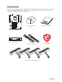
Unpacking
Unpacking
Thank you for buying the MSI
®
B360-F PRO/ H310-F PRO motherboard. Check to make
sure your motherboard box contains the following items. If something is missing,
contact your dealer as soon as possible.
SATA Cable x2
24-pin to 2-pin Adapter x4
Drivers & Utilities
Disc
Installation Guide
I/O Shield
Motherboard
Case Badge

2
Safety Information
Safety Information
y The components included in this package are prone to damage from electrostatic
discharge (ESD). Please adhere to the following instructions to ensure successful
computer assembly.
y Ensure that all components are securely connected. Loose connections may cause
the computer to not recognize a component or fail to start.
y Hold the motherboard by the edges to avoid touching sensitive components.
y It is recommended to wear an electrostatic discharge (ESD) wrist strap when
handling the motherboard to prevent electrostatic damage. If an ESD wrist strap is
not available, discharge yourself of static electricity by touching another metal object
before handling the motherboard.
y Store the motherboard in an electrostatic shielding container or on an anti-static pad
whenever the motherboard is not installed.
y Before turning on the computer, ensure that there are no loose screws or metal
components on the motherboard or anywhere within the computer case.
y Do not boot the computer before installation is completed. This could cause
permanent damage to the components as well as injury to the user.
y If you need help during any installation step, please consult a certified computer
technician.
y Always turn off the power supply and unplug the power cord from the power outlet
before installing or removing any computer component.
y Keep this user guide for future reference.
y Keep this motherboard away from humidity.
y Make sure that your electrical outlet provides the same voltage as is indicated on the
PSU, before connecting the PSU to the electrical outlet.
y Place the power cord such a way that people can not step on it. Do not place anything
over the power cord.
y All cautions and warnings on the motherboard should be noted.
y If any of the following situations arises, get the motherboard checked by service
personnel:
Liquid has penetrated into the computer.
The motherboard has been exposed to moisture.
The motherboard does not work well or you can not get it work according to user
guide.
The motherboard has been dropped and damaged.
The motherboard has obvious sign of breakage.
y Do not leave this motherboard in an environment above 60°C (140°F), it may damage
the motherboard.

3
Contents
Contents
Unpacking .............................................................................................................. 1
Safety Information ................................................................................................. 2
Specifications ......................................................................................................... 5
Block Diagram ...................................................................................................... 9
Rear I/O Panel ..................................................................................................... 10
LAN Port LED Status Table................................................................................... 10
Debug LED Table .................................................................................................. 10
Realtek HD Audio Manager .................................................................................. 11
Overview of Components .................................................................................... 12
B360-F PRO .......................................................................................................... 12
H310-F PRO .......................................................................................................... 13
CPU Socket ........................................................................................................... 15
DIMM Slots ............................................................................................................ 17
PCI_E1~18: PCIe Expansion Slots ........................................................................ 19
PCIe Slot LEDs ...................................................................................................... 20
JPS_ON1~4: Multiple Power Supplies Turn On Connectors ................................ 20
CPU_PWR1, ATX_PWR1, GPU_PWR1~3 (optional): Power Connectors .............. 21
CPU_FAN1, SYS_FAN1: Fan Connectors .............................................................. 22
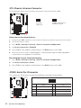
SATA1~4: SATA 6Gb/s Connectors ....................................................................... 23
JFP1, JFP2: Front Panel Connectors ................................................................... 23
JAUD1: Front Audio Connector ............................................................................ 24
JTPM1: TPM Module Connector ........................................................................... 24
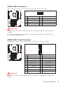
JUSB1: USB 2.0 Connector .................................................................................. 25
JUSB2: USB 3.1 Gen1 Connector ......................................................................... 25
JCI1: Chassis Intrusion Connector ....................................................................... 26
JCOM1: Serial Port Connector ............................................................................. 26
POWER1, RESET1: Power Button, Reset Button ................................................. 27
CLR_CMOS1: Clear CMOS Button ........................................................................ 27
JBAT1: Clear CMOS (Reset BIOS) Jumper ........................................................... 27
BIOS Setup ........................................................................................................... 28
Entering BIOS Setup ............................................................................................. 28
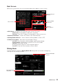
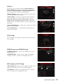
Boot Screen .......................................................................................................... 29
Mining Mode ......................................................................................................... 29
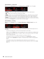
Resetting BIOS ...................................................................................................... 30
Updating BIOS ....................................................................................................... 30
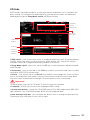
EZ Mode ................................................................................................................ 31
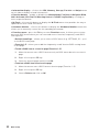
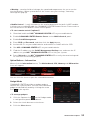
Advanced Mode .................................................................................................... 33

4
Contents
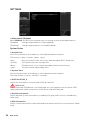
SETTINGS .............................................................................................................. 34
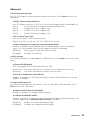
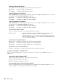
Advanced ............................................................................................................... 35
Boot ....................................................................................................................... 40
Security ................................................................................................................. 41
Save & Exit ............................................................................................................ 42
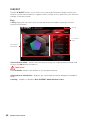
OC .......................................................................................................................... 43
M-FLASH .............................................................................................................. 49
OC PROFILE .......................................................................................................... 50
HARDWARE MONITOR .......................................................................................... 51
Software Description ........................................................................................... 52
Installing Windows
®
10 ......................................................................................... 52
Installing Drivers .................................................................................................. 52
Installing Utilities ................................................................................................. 52
APP MANAGER ..................................................................................................... 53
LIVE UPDATE 6 ...................................................................................................... 54
COMMAND CENTER ............................................................................................. 56
X-BOOST ............................................................................................................... 60
DPC LATENCY TUNER .......................................................................................... 62
SMART TOOL ......................................................................................................... 63
RAMDISK............................................................................................................... 65
NETWORK MANAGER ........................................................................................... 66
Troubleshooting .................................................................................................. 68

5
Specifications
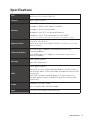
Specifications
CPU
Supports 8th Gen Intel
®
Core™, Pentium
®
Gold and Celeron
®
processors for Socket LGA1151
Chipset Intel
®
B360 Chipset
Memory
y 2x DDR4 memory slots, support up to 32GB
y Supports DDR4 2666/ 2400/ 2133 MHz
y Supports Dual-Channel mode
y Supports non-ECC, un-buffered memory
y Supports Intel
®
Extreme Memory Profile (XMP)
* Please refer www.msi.com for more information on compatible memory.
Expansion Slot
y 1x PCIe 3.0 x16 slot
y 17x PCIe 3.0 x1 slots (B360-F PRO)/ 12x PCIe 2.0 x1 slots
(H310-F PRO)
Onboard Graphics
y 1x DVI-D port, supports a maximum resolution of
1920x1200@60Hz
y 1x HDMI™ port 1.4, supports a maximum resolution of
4096x2160@30Hz
Storage
Intel
®
B360 Chipset
y 4x SATA 6Gb/s ports
USB
Intel
®
B360 Chipset
y 4x USB 3.1 Gen1 (SuperSpeed USB) ports (2 Type-A ports
on the back panel, 2 ports available through the internal USB
connector)
y 6x USB 2.0 (High-speed USB) ports (4 Type-A ports on
the back panel, 2 ports available through the internal USB
connector)
Audio
y Realtek
®
ALC887 Codec
y 7.1-Channel High Definition Audio
LAN 1x Intel I219-V Gigabit LAN controller
Continued on next page

6
Specifications
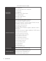
Continued from previous page
Back Panel
Connectors
y 4x Debug LEDs
y 1x PS/2 keyboard/ mouse combo port
y 1x DVI-D port
y 1x HDMI port
y 2x USB 3.1 Gen1 Type-A ports
y 1x LAN (RJ45) port
y 4x USB 2.0 Type-A ports
y 3x Audio jacks
Internal Connectors
y 1x 24-pin ATX main power connector
y 1x 8-pin ATX 12V power connector
y 3x 4-pin PCIe power connectors (B360-F PRO)/ 2x 4-pin
PCIe power connectors (H310-F PRO)
y 4x 2-pin PS_ON connectors
y 4x SATA 6Gb/s connectors
y 1x USB 3.1 Gen1 connector (supports additional 2 USB 3.1
Gen1 ports)
y 1x USB 2.0 connector (supports additional 2 USB 2.0 ports)
y 1x 4-pin CPU fan connector
y 1x 4-pin system fan connector
y 1x Front panel audio connector
y 2x Front panel connectors
y 1x TPM module connector
y 1x Chassis Intrusion connector
y 1x Serial port connector
y 1x Clear CMOS jumper
y 1x Power button
y 1x Reset button
y 1x Clear CMOS button
I/O Controller NUVOTON NCT5567 Controller Chip
Hardware Monitor
y CPU/System temperature detection
y CPU/System fan speed detection
y CPU/System fan speed control
Continued on next page

7
Specifications
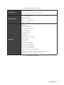
Continued from previous page
Form Factor
y ATX Form Factor
y 12.0 in. x 8.9 in. (30.5 cm x 22.5 cm)
BIOS Features
y 1x 128 Mb flash
y UEFI AMI BIOS
y ACPI 6.1, SMBIOS 2.8
y Multi-language
Software
y Drivers
y APP MANAGER
y COMMAND CENTER
y LIVE UPDATE 6
y SMART TOOL
y RAMDISK
y DPC LATENCY TUNER
y FAST BOOT
y X-BOOST
y SUPER CHARGER
y NETWORK MANAGER
y CPU-Z MSI GAMING
y Intel
®
Extreme Tuning Utility
y Google Chrome™ ,Google Toolbar, Google Drive
y Norton™ Internet Security Solution
Continued on next page

8
Specifications
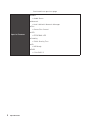
Continued from previous page
Special Features
y Audio
Audio Boost
y Network
Intel LAN with Network Manager
y Fan
Smart Fan Control
y LED
EZ DEBUG LED
y Stability
7000+ Quality Test
y VR
VR Ready
y BIOS
Click BIOS 5

9
Block Diagram
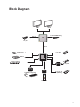
Block Diagram
2 Channel DDR4 Memory
USB 3.1 Gen1
PCI_E1
PCI_E2~6
PCI_E7~13
USB 2.0
P/S2 Mouse / Keyboard
Audio Jacks
DMI 3.0
B360/ H310
CPU
NV5567
Super I/O
ASM1187E
Realtek
ALC887
PCIe x16
HDMI
PCI_E14~18
(B360 only)
DVI-D
SATA 6Gb/s

10
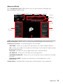
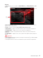
Rear I/O Panel
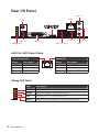
Rear I/O Panel
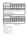
Link/ Activity LED
Status Description
Off No link
Yellow Linked
Blinking Data activity
Speed LED
Status Description
Off 10 Mbps connection
Green 100 Mbps connection
Orange 1 Gbps connection
LAN Port LED Status Table
Debug LED Table
LAN
USB 2.0
USB 3.1 Gen1 Mic
Line-Out
Line-In
DVI-D
PS/2
USB 2.0
Debug LED
LED Description
CPU Indicates CPU is not detected or fail.
DRAM Indicates DRAM is not detected or fail.
VGA Indicates GPU is not detected or fail.
BOOT Indicates the booting device is not detected or fail.

11
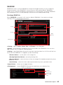
Rear I/O Panel
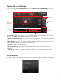
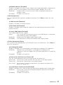
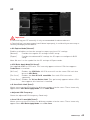
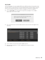
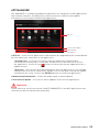
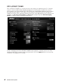
Realtek HD Audio Manager
After installing the Realtek HD Audio driver, the Realtek HD Audio Manager icon will
appear in the system tray. Double click on the icon to launch.
y Device Selection - allows you to select a audio output source to change the related
options. The check sign indicates the devices as default.
y Application Enhancement - the array of options will provide you a complete guidance
of anticipated sound effect for both output and input device.
y Main Volume - controls the volume or balance the right/left side of the speakers that
you plugged in front or rear panel by adjust the bar.
y Profiles - toggles between profiles.
y Advanced Settings - provides the mechanism to deal with 2 independent audio
streams.
y Jack Status - depicts all render and capture devices currently connected with your
computer.
y Connector Settings - configures the connection settings.
Auto popup dialog
When you plug into a device at an audio jack, a dialogue window will pop up asking you
which device is current connected.
Jack Status
Device
Selection
Connector
Settings
Profiles
Main Volume
Application
Enhancement
Advanced
Settings

12
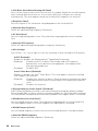
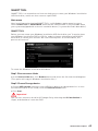
Overview of Components
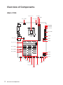
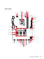
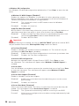
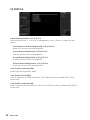
Overview of Components
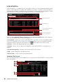
B360-F PRO
PCI_E1~18
GPU_PWR1
GPU_PWR2
GPU_PWR3
JTPM1
CLR_CMOS1
POWER1
RESET1
JCOM1
CPU Socket
CPU_PWR1
ATX_PWR1
JPS_ON1
JPS_ON2
JPS_ON3
JPS_ON4
JUSB1
JUSB2
JBAT1
DIMMA1
DIMMB1
JCI1
SATA3
SATA4
SATA2
SATA1
CPU_FAN1
SYS_FAN1
JFP2
JFP1
JAUD1

13
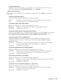
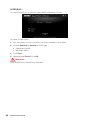
Overview of Components
H310-F PRO
PCI_E1~13
GPU_PWR1
GPU_PWR2
JTPM1
CLR_CMOS1
POWER1
RESET1
JCOM1
CPU Socket
CPU_PWR1
ATX_PWR1
JPS_ON1
JPS_ON2
JPS_ON3
JPS_ON4
JUSB1
JUSB2
JBAT1
DIMMA1
DIMMB1
JCI1
SATA3
SATA4
SATA2
SATA1
CPU_FAN1
SYS_FAN1
JFP2
JFP1
JAUD1

14
Overview of Components
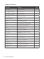
Component Contents
Port Name Port Type Page
CLR_CMOS1 Clear CMOS Button 27
CPU_FAN1, SYS_FAN1 Fan Connectors 22
CPU_PWR1, ATX_PWR1,
GPU_PWR1~3 (optional)
Power Connectors 21
CPU Socket LGA1151 CPU Socket 15
DIMMA1, DIMMB1 DIMM Slots 17
JAUD1 Front Audio Connector 24
JBAT1 Clear CMOS (Reset BIOS) Jumper 27
JCI1 Chassis Intrusion Connector 26
JCOM1 Serial Port Connector 26
JFP1, JFP2 Front Panel Connectors 23
JPS_ON1~4
Multiple Power Supplies Turn On
Connectors
20
JTPM1 TPM Module Connector 24
JUSB1 USB 2.0 Connector 25
JUSB2 USB 3.1 Gen1 Connector 25
PCI_E1~18 PCIe Expansion Slots 19
POWER1, RESET1 Power Button, Reset Button 27
SATA1~4 SATA 6Gb/s Connectors 23

15
Overview of Components
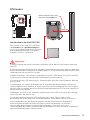
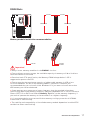
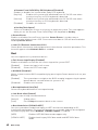
CPU Socket
Introduction to the LGA 1151 CPU
The surface of the LGA 1151 CPU has
two notches and a golden triangle to
assist in correctly lining up the CPU for
motherboard placement. The golden
triangle is the Pin 1 indicator.
Important
y
Always unplug the power cord from the power outlet before installing or removing
the CPU.
y
Please retain the CPU protective cap after installing the processor. MSI will deal with
Return Merchandise Authorization (RMA) requests if only the motherboard comes with
the protective cap on the CPU socket.
y
When installing a CPU, always remember to install a CPU heatsink. A CPU heatsink
is necessary to prevent overheating and maintain system stability.
y
Confirm that the CPU heatsink has formed a tight seal with the CPU before booting
your system.
y
Overheating can seriously damage the CPU and motherboard. Always make sure
the cooling fans work properly to protect the CPU from overheating. Be sure to apply
an even layer of thermal paste (or thermal tape) between the CPU and the heatsink to
enhance heat dissipation.
y
Whenever the CPU is not installed, always protect the CPU socket pins by covering
the socket with the plastic cap.
y
If you purchased a separate CPU and heatsink/ cooler, Please refer to the
documentation in the heatsink/ cooler package for more details about installation.
y
This motherboard is designed to support overclocking. Before attempting to
overclock, please make sure that all other system components can tolerate
overclocking. Any attempt to operate beyond product specifications is not
recommended. MSI
®
does not guarantee the damages or risks caused by inadequate
operation beyond product specifications.
50.83 mm
Distance from the center of the
CPU to the nearest DIMM slot.

16
Overview of Components
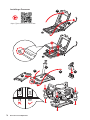
https://youtu.be/4ce91YC3Oww
Installing a Processor
1
2
3
6
4
5
7
8
9

17
Overview of Components
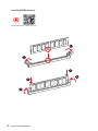
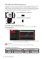
DIMM Slots
DIMMA1 DIMMB1
Channel A Channel B
Memory module installation recommendation
Important
y
Always insert memory modules in the DIMMA1 slot first.
y
Due to chipset resource usage, the available capacity of memory will be a little less
than the amount of installed.
y
Based on Intel CPU specification, the Memory DIMM voltage below 1.35V is
suggested to protect the CPU.
y
Please note that the maximum capacity of addressable memory is 4GB or less
for 32-bit Windows OS due to the memory address limitation. Therefore, we
recommended that you to install 64-bit Windows OS if you want to install more than
4GB memory on the motherboard.
y
Some memory may operate at a lower frequency than the marked value when
overclocking due to the memory frequency operates dependent on its Serial Presence
Detect (SPD). Go to BIOS and find the Memory Try It! to set the memory frequency if
you want to operate the memory at the marked or at a higher frequency.
y
It is recommended to use a more efficient memory cooling system for full DIMMs
installation or overclocking.
y
The stability and compatibility of installed memory module depend on installed CPU
and devices when overclocking.
DIMMA1
DIMMB1
DIMMA1

18
Overview of Components
Installing DDR4 memory
http://youtu.be/T03aDrJPyQs
1
1
2
2
3
3

19
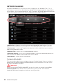
Overview of Components
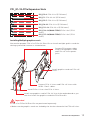
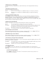
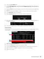
PCI_E1~18: PCIe Expansion Slots
PCI_E1: PCIe 3.0 x16 (CPU lanes)
PCI_E2~4: PCIe 2.0 x1 (PCH lanes)
PCI_E5~7: PCIe 2.0 x1 (PCH lanes)
PCI_E8~10: PCIe 2.0 x1 (PCH lanes)
PCI_E11~13: PCIe 2.0 x1 (PCH lanes)
PCI_E14~16 (B360-F PRO): PCIe 2.0 x1 (PCH
lanes)
PCI_E17~18 (B360-F PRO): PCIe 2.0 x1 (PCH
lanes)
Installing Multiple graphics cards
You need to prepare PCIe x1 to PCIe x16 Riser Kits to install multiple grahics cards for
mining system and connect as shown below.
Connect PCIe power cables
from PSU to graphics cards
and PCIe x16 risers power
jacks.
Install graphics cards on PCIe x16
risers.
Install one graphics card in PCIe x16 slot of the motherboard or you
can also install the graphics card with PCIe Riser Kit.
Connect PCIe x1 risers and PCIe x16 risers with
USB 3.1 Gen1 cables.
Install PCIe x1 risers into PCIe x1 slots.
Important
y
PCIe x1 to PCIe x16 Riser Kits are purchased separately.
y
Make sure the graphics cards are locked by the latch at the end of the PCIe x16 slots.

20
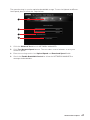
Overview of Components
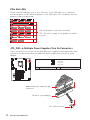
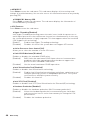
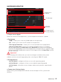
PCIe Slot LEDs
There is an LED indicator next to each PCIe slot. If the LED light is on, it indicates
that the graphics card is working properly. If the LED light is off, it indicates that the
graphics card is not detected.
ON: The graphics card works normally.
OFF: The slot is empty or the graphics card has
an error.
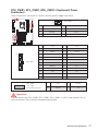
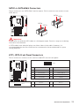
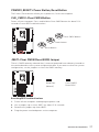
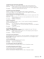
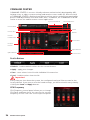
JPS_ON1~4: Multiple Power Supplies Turn On Connectors
These connectors use to turn on the multiple power supplies at the same time. Each
connector can be connected to an additional power supply with a 24-pin to 2-pin
adapter.
JPS_ON1
JPS_ON2
JPS_ON3
JPS_ON4
1
1 JPS_ON 2 Ground
Additional power supply 24 pin
connector
24-pin to 2-pin adapter
JPS_ON connector
La pagina si sta caricando...
La pagina si sta caricando...
La pagina si sta caricando...
La pagina si sta caricando...
La pagina si sta caricando...
La pagina si sta caricando...
La pagina si sta caricando...
La pagina si sta caricando...
La pagina si sta caricando...
La pagina si sta caricando...
La pagina si sta caricando...
La pagina si sta caricando...
La pagina si sta caricando...
La pagina si sta caricando...
La pagina si sta caricando...
La pagina si sta caricando...
La pagina si sta caricando...
La pagina si sta caricando...
La pagina si sta caricando...
La pagina si sta caricando...
La pagina si sta caricando...
La pagina si sta caricando...
La pagina si sta caricando...
La pagina si sta caricando...
La pagina si sta caricando...
La pagina si sta caricando...
La pagina si sta caricando...
La pagina si sta caricando...
La pagina si sta caricando...
La pagina si sta caricando...
La pagina si sta caricando...
La pagina si sta caricando...
La pagina si sta caricando...
La pagina si sta caricando...
La pagina si sta caricando...
La pagina si sta caricando...
La pagina si sta caricando...
La pagina si sta caricando...
La pagina si sta caricando...
La pagina si sta caricando...
La pagina si sta caricando...
La pagina si sta caricando...
La pagina si sta caricando...
La pagina si sta caricando...
La pagina si sta caricando...
La pagina si sta caricando...
La pagina si sta caricando...
La pagina si sta caricando...
La pagina si sta caricando...
La pagina si sta caricando...
La pagina si sta caricando...
La pagina si sta caricando...
-
 1
1
-
 2
2
-
 3
3
-
 4
4
-
 5
5
-
 6
6
-
 7
7
-
 8
8
-
 9
9
-
 10
10
-
 11
11
-
 12
12
-
 13
13
-
 14
14
-
 15
15
-
 16
16
-
 17
17
-
 18
18
-
 19
19
-
 20
20
-
 21
21
-
 22
22
-
 23
23
-
 24
24
-
 25
25
-
 26
26
-
 27
27
-
 28
28
-
 29
29
-
 30
30
-
 31
31
-
 32
32
-
 33
33
-
 34
34
-
 35
35
-
 36
36
-
 37
37
-
 38
38
-
 39
39
-
 40
40
-
 41
41
-
 42
42
-
 43
43
-
 44
44
-
 45
45
-
 46
46
-
 47
47
-
 48
48
-
 49
49
-
 50
50
-
 51
51
-
 52
52
-
 53
53
-
 54
54
-
 55
55
-
 56
56
-
 57
57
-
 58
58
-
 59
59
-
 60
60
-
 61
61
-
 62
62
-
 63
63
-
 64
64
-
 65
65
-
 66
66
-
 67
67
-
 68
68
-
 69
69
-
 70
70
-
 71
71
-
 72
72


MSI 7B25 Manuale del proprietario
- Categoria
- Schede madri
- Tipo
- Manuale del proprietario
- Questo manuale è adatto anche per
in altre lingue
- English: MSI 7B25 Owner's manual