
kOriginalbetriebsanleitung
Elektro-Bodenhacke
Original operating instructions
Electric Hoe
pMode d’emploi d’origine
de la bineuse électrique
CIstruzioni per l’uso originali
Elettrozappa
NOriginele handleiding
elektrische bodemfrees
UOriginal-bruksanvisning
Elektrisk jordfräs
QInstrucţiuni de utilizare originale
Prăşitor electric
jOriginální návod k obsluze
Elektrická motyčka
WOriginálny návod na obsluhu
Elektrický kyprič pôdy
Art.-Nr.: 34.310.15 I.-Nr.: 11020 E-EBH 750
Anleitung_E_EBH_750_SPK7:_ 28.10.2010 11:05 Uhr Seite 1

2
Vor Inbetriebnahme Bedienungsanleitung und
Sicherheitshinweise lesen und beachten
Read and follow the operating instructions and safety information
before using for the first time.
Avant la mise en service, lisez le mode dʼemploi et les consignes de
sécurité et respectez-les.
Prima della messa in esercizio leggete e osservate le istruzioni per
lʼuso e le avvertenze di sicurezza.
Vóór ingebruikneming de handleiding en de veiligheidsvoorschriften
lezen en in acht nemen!
Läs igenom och beakta bruksanvisningen och säkerhetsanvisningarna
före användning.
Înainte de punerea în funcøiune se vor citi μi respecta instrucøiunile de
folosire μi indicaøiile de siguranøå.
jPřed uvedením do provozu si přečíst návod k obsluze a bezpečnostní
předpisy a oboje dodržovat.
WPred uvedením do prevádzky si prečítajte a dodržiavajte návod na
obsluhu a bezpečnostné pokyny.
Anleitung_E_EBH_750_SPK7:_ 28.10.2010 11:05 Uhr Seite 2

3
1
5
6a
6
1
6b
4
3
2
236
2
1
357
810
9
11
12
Anleitung_E_EBH_750_SPK7:_ 28.10.2010 11:05 Uhr Seite 3

4
4
5 6
7 8
6
1
9
9
12 12
8
621
3
6
5
11
11
5
8
Anleitung_E_EBH_750_SPK7:_ 28.10.2010 11:05 Uhr Seite 4

5
910
11 12
6c
5
6
1
10
10
6
13
6b
7
7
6a
114
AB
Anleitung_E_EBH_750_SPK7:_ 28.10.2010 11:05 Uhr Seite 5

6
15
Anleitung_E_EBH_750_SPK7:_ 28.10.2010 11:05 Uhr Seite 6

Achtung!
Beim Benutzen von Geräten müssen einige
Sicherheitsvorkehrungen eingehalten werden, um
Verletzungen und Schäden zu verhindern. Lesen Sie
diese Bedienungsanleitung / Sicherheitshinweise
deshalb sorgfältig durch. Bewahren Sie diese gut
auf, damit Ihnen die Informationen jederzeit zur
Verfügung stehen. Falls Sie das Gerät an andere
Personen übergeben sollten, händigen Sie diese
Bedienungsanleitung / Sicherheitshinweise bitte mit
aus. Wir übernehmen keine Haftung für Unfälle oder
Schäden, die durch Nichtbeachten dieser Anleitung
und den Sicherheitshinweisen entstehen.
1. Sicherheitshinweise
Die entsprechenden Sicherheitshinweise finden Sie
im beiliegenden Heftchen!
WARNUNG
Lesen Sie alle Sicherheitshinweise und
Anweisungen. Versäumnisse bei der Einhaltung der
Sicherheitshinweise und Anweisungen können
elektrischen Schlag, Brand und/oder schwere
Verletzungen verursachen.
Bewahren Sie alle Sicherheitshinweise und
Anweisungen für die Zukunft auf.
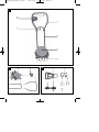
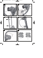
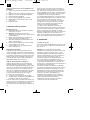
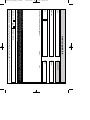
2. Gerätebeschreibung (Bild 1-3, 12)
1. Oberer Schubbügel
2. Unterer Schubbügel
3. Motoreinheit
4. Hackmesser
5. Kabelzugentlastung
6. 2-Hand-Sicherheitsschalter
6a Zweipunktschalter
6b Schalthebel
6c Netzanschlussstecker
7. Kabelbefestigungsclips
8. 2x Schraube für Montage oberer Schubbügel
9. 2x Schraube für Montage unterer Schubbügel
10. 2x Schraube für Montage 2-Hand-
Sicherheitsschalter
11. 2x Mutter M6
12. 2x Flügelmutter
3. Bestimmungsgemäße Verwendung
Das Gerät ist geeignet zum Umgraben von Erde
(z.B. Gartenbeete). Beachten Sie unbedingt die
Einschränkungen in den Sicherheitshinweisen.
Das Gerät darf nur nach seiner Bestimmung
verwendet werden. Jede weitere darüber
hinausgehende Verwendung ist nicht
bestimmungsgemäß. Für daraus hervorgerufene
Schäden oder Verletzungen aller Art haftet der
Benutzer/Bediener und nicht der Hersteller.
Bitte beachten Sie, dass unsere Geräte
bestimmungsgemäß nicht für den gewerblichen,
handwerklichen oder industriellen Einsatz konstruiert
wurden. Wir übernehmen keine Gewährleistung,
wenn das Gerät in Gewerbe-, Handwerks- oder
Industriebetrieben sowie bei gleichzusetzenden
Tätigkeiten eingesetzt wird.
Die Einhaltung der vom Hersteller beigefügten
Gebrauchsanweisung ist Voraussetzung für den
ordnungsgemäßen Gebrauch des Gerätes. Die
Gebrauchsanweisung enthält auch die Betriebs-,
Wartungs- und Instandhaltungsbedingungen.
Aus Sicherheitsgründen darf das Gerät nicht
verwendet werden als Antriebsaggregat für andere
Arbeitswerkzeuge und Werkzeugsätze jeglicher Art.
4. Technische Daten
Netzspannung: 230V ~ 50Hz
Leistungsaufnahme: 750 W
Arbeitsbreite: 30 cm
Hacken Ø: 22 cm
Leerlaufdrehzahl: 400 min-1
Anzahl der Messer: 4 Stück
Schalldruckpegel LpA: 70 dB(A)
Schallleistungspegel LWA: 93 dB(A)
Vibration am Holm ahv: <2,5 m/s2
7
D
Anleitung_E_EBH_750_SPK7:_ 28.10.2010 11:05 Uhr Seite 7

8
Beschränken Sie die Geräuschentwicklung und
Vibration auf ein Minimum!
Verwenden Sie nur einwandfreie Geräte.
Warten und reinigen Sie das Gerät regelmäßig.
Passen Sie Ihre Arbeitsweise dem Gerät an.
Überlasten Sie das Gerät nicht.
Lassen Sie das Gerät gegebenenfalls
überprüfen.
Schalten Sie das Gerät aus, wenn es nicht
benutzt wird.
Tragen Sie Handschuhe.
5. Vor Inbetriebnahme
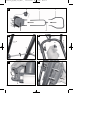
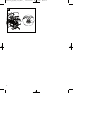
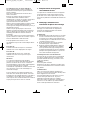
Montage (Abb. 4-11)
Legen Sie die Motoreinheit und die Schubbügel
hintereinander auf den Boden (Abb. 4).
Achtung! Vergessen Sie nicht die
Kabelzugentlastung (Abb. 6/Pos.5) über den
unteren Schubbügel zu schieben.
Schieben Sie den unteren Schubbügel auf die
Schubbügelhalter und verschrauben Sie diese
miteinander (Abb. 5).
Verschrauben Sie nun den oberen mit dem
unteren Schubbügel (Abb. 6).
Montieren Sie den 2-Hand-Sicherheitsschalter
wie in Abb. 7-10 gezeigt.
Befestigen Sie das Kabel mit den beiliegenden
Kabelbefestigungsclips (Abb.11/7)
Stromanschluss
Das Gerät kann an jede Lichtsteckdose (mit 230 Volt
Wechselstrom) angeschlossen werden. Es ist jedoch
nur eine Schuko-Steckdose zulässig, zu deren
Absicherung ein Leitungs-Schutzschalter für 16A
vorzusehen ist. Außerdem muss ein Fehlerstrom-
Schutzschalter (RCD) mit max. 30 mA vorgeschaltet
sein!
Geräteanschlussleitung
Verwenden Sie bitte nur Geräteanschlussleitungen,
welche nicht beschädigt sind. Die
Geräteanschlussleitung darf nicht beliebig lang sein
(max. 50 m), da sonst die Leistung des Elektromotors
vermindert wird. Die Geräteanschlussleitung muss
einen Querschnitt von 3 x 1,5mm2haben. An
Geräteanschlussleitungen entstehen besonders
häufig Isolationsschäden.
Ursachen hierfür sind u.a.:
Risse durch Alterung der Isolation
Knickstellen durch unsachgemäße Befestigung
oder Führung der Geräteanschlussleitung
Solche schadhaften Geräteanschlussleitungen
werden verwendet, obwohl sie aufgrund der
Isolationsschäden lebensgefährlich sind. Kabel,
Stecker und Kupplungsdosen sollen den nachfolgend
aufgelisteten Bedingungen genügen.
Geräteanschlussleitungen zum Anschluss von
Bodenhacken müssen Gummiisolierungen haben.
Die Geräteanschlussleitungen müssen mindestens
vom Typ H05RN-F und 3-adrig sein. Ein Aufdruck
der Typenbezeichnung auf der
Geräteanschlussleitung ist vorgeschrieben. Kaufen
Sie nur Geräteanschlussleitungen mit
Kennzeichnung! Die Stecker und Kupplungsdosen an
Geräteanschlussleitungen müssen aus Gummi
bestehen und spritzwassergeschützt sein. Die
Geräteanschlussleitungen dürfen nicht beliebig lang
sein. Längere Geräteanschlussleitungen erfordern
größere Leiterquerschnitte.
Geräteanschlussleitungen und Verbindungsleitungen
müssen regelmäßig auf Schäden geprüft werden.
Achten Sie darauf, dass die Leitungen bei der
Prüfung stromlos sind. Wickeln Sie die
Geräteanschlussleitung ganz ab. Überprüfen Sie
auch die Geräteanschlussleitungseinführungen an
Steckern und Kupplungsdosen auf Knickstellen.
6. Bedienung
6.1. Inbetriebnahme
Schließen Sie die Geräteanschlussleitung an den
Stecker (Bild 12 / Pos. 6c) an und sichern Sie die
Anschlussleitung mit der Zugentlastung
(Bild 12/Pos. 5).
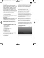
Achtung! Um ein ungewolltes Einschalten des
Gerätes zu verhindern, ist der Schubbügel (Bild
13/Pos. 1) mit einem Zweipunktschalter (Bild 13 /
Pos. 6a) ausgestattet, welcher gedrückt werden
muss, bevor der Schalthebel (Bild 13 / Pos. 6b)
gedrückt werden kann. Wird der Schalthebel
losgelassen schaltet sich das Gerät ab.
Führen Sie diesen Vorgang einige Male durch, damit
Sie sicher sind, dass Ihr Gerät korrekt funktioniert.
Bevor Sie Reparatur- oder Wartungsarbeiten am
Gerät vornehmen, müssen Sie sich vergewissern,
dass sich die Hackmesser nicht drehen und das
Gerät vom Netz getrennt ist.
Der durch die Führungsholme gegebene
Sicherheitsabstand zwischen Gerät und Benutzer ist
stets einzuhalten.
Bei Fahrtrichtungsänderungen an Böschungen und
Hängen ist besondere Vorsicht geboten.
Achten Sie auf einen sicheren Stand, tragen Sie
Schuhe mit rutschfesten, griffigen Sohlen und lange
Hosen.
D
Anleitung_E_EBH_750_SPK7:_ 28.10.2010 11:05 Uhr Seite 8

9
D
Arbeiten Sie immer quer zum Hang.
Üben Sie besondere Vorsicht beim Rückwärts-
bewegen und beim Ziehen des Gerätes,
Stolpergefahr!
6.2. Hinweise zum richtigen Arbeiten
Stellen Sie das Gerät vor die zu bearbeitende Fläche
und halten es am Schubbügel gut fest bevor Sie das
Gerät einschalten.
Führen Sie die Hackmesser über die zu bearbeitende
Fläche.
Zur Erzielung von sauber bearbeitetem Boden das
Gerät in möglichst geraden Bahnen führen. Dabei
sollten sich diese Bahnen immer um einige
Zentimeter überlappen, damit keine Streifen übrig
bleiben.
Schalten Sie den Motor rechtzeitig ab wenn Sie am
Ende der zu bearbeitenden Fläche angekommen
sind. Wenn das Gerät angehoben wird (z.B. bei
Richtungsänderung) muss der Motor abgeschaltet
werden.
Die Unterseite des Gerätes sauber halten und
Erdablagerungen unbedingt entfernen. Ablagerungen
erschweren den Startvorgang und beeinträchtigen
die Arbeitstiefe.
An Hängen die Arbeitsrichtung quer zum Hang legen.
Bevor irgendwelche Kontrollen der Hackmesser
durchgeführt werden Motor abschalten und
Netzkabel abziehen.
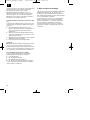
Für die Saatvorbereitung empfehlen wir einen der
Arbeitswege, wie sie in Bild 14 gezeigt werden.
Arbeitsweg A:
Hacken Sie zuerst Bahn für Bahn, dann ein zweites
Mal 90 Grad versetzt dazu.
Arbeitsweg B:
Hacken Sie zuerst Bahn für Bahn, dann ein zweites
Mal, aber es überlappen sich die Laufwege.
Achtung!
Die Hackmesser drehen nach dem Ausschalten des
Motors noch einige Sekunden weiter. Versuchen Sie
nie, diese zu stoppen. Falls die in Bewegung
befindlichen Hackmesser auf einen Gegenstand
schlagen, das Gerät abschalten und warten bis die
Hackmesser vollkommen still stehen. Kontrollieren
Sie anschließend den Zustand der Hackmesser.
Falls diese beschädigt sind müssen sie
ausgewechselt werden.
Legen Sie die verwendete Geräteanschlussleitung
schleifenförmig vor der verwendeten Steckdose auf
die Erde. Arbeiten Sie von der Steckdose bzw. vom
Kabel weg und achten Sie darauf, dass die
Geräteanschlussleitung immer im bearbeiteten
Boden liegt, damit die Geräteanschlussleitung nicht
von den Hackmessern überfahren wird.
7. Austausch der Netzanschlussleitung
Wenn die Netzanschlussleitung dieses Gerätes
beschädigt wird, muss sie durch den Hersteller oder
seinen Kundendienst oder eine ähnlich qualifizierte
Person ersetzt werden, um Gefährdungen zu
vermeiden.
8. Reinigung, Wartung und
Ersatzteilbestellung
Wartungs- und Reinigungsarbeiten am Gerät sowie
das Abnehmen von Schutzeinrichtungen darf nur bei
stehendem Motor und gezogener Netzleitung
vorgenommen werden.
8.1 Reinigung
Halten Sie Schutzvorrichtungen, Luftschlitze und
Motorengehäuse so staub- und schmutzfrei wie
möglich. Reiben Sie das Gerät mit einem
sauberen Tuch ab oder blasen Sie es mit
Druckluft bei niedrigem Druck aus.
Wir empfehlen, dass Sie das Gerät direkt nach
jeder Benutzung reinigen.
Reinigen Sie das Gerät regelmäßig mit einem
feuchten Tuch und etwas Schmierseife.
Verwenden Sie keine Reinigungs- oder
Lösungsmittel; diese könnten die Kunststoffteile
des Gerätes angreifen. Achten Sie darauf, dass
kein Wasser in das Geräteinnere gelangen kann.
8.2 Austausch der Hackmesser
Aus Sicherheitsgründen empfehlen wir, den
Austausch der Hackmesser von einem autorisierten
Fachmann vornehmen zu lassen (siehe Adresse auf
der Garantieurkunde).
Achtung!
Arbeitshandschuhe tragen! Verwenden Sie nur
Original-Ersatzteile, da andernfalls Funktion und
Sicherheit unter Umständen nicht gewährleistet sind.
Anleitung_E_EBH_750_SPK7:_ 28.10.2010 11:05 Uhr Seite 9

10
D
8.3 Wartung
Sorgen Sie dafür, dass alle Befestigungselemente
(Schrauben, Mutter usw.) stets fest angezogen sind,
sodass Sie mit dem Gerät sicher arbeiten können.
Lagern Sie das Gerät in einem trockenen Raum. Für
eine lange Lebensdauer sollten alle Metallteile
gereinigt und anschließend geölt werden.
Säubern Sie die Kunststoffteile des Gerätes
möglichst mit Bürsten oder Lappen. Verwenden Sie
keine Lösungsmittel um den Schmutz zu beseitigen.
Vor jedem Saisonbeginn den Zustand des Gerätes
unbedingt überprüfen. Wenden Sie sich bei
Reparaturen an unsere Kundendienststelle (siehe
Adresse auf der Garantieurkunde).
Halten Sie alle beweglichen Teile leichtgängig (ggf.
schmieren).
Überprüfung des Getriebeöls (Abb. 15)
Die Ölablassschraube befindet sich an der rechten
Seite des Getriebekasten. Demontieren Sie wenn
nötig die Messer.
Kippen Sie die Elektro-Bodenhacke auf die linke
Seite, um zu verhindern, dass Schmutz oder
Fremdkörper in das Getriebe gelangen.
Öffnen Sie mit Hilfe eines 5 mm Inbusschlüssel
die Ölablassschraube und lassen Sie das Öl in
einen Behälter abfließen.
Füllen Sie bis zur Oberkante neues und
hochwertiges Motorschmieröl nach.
Schrauben Sie die Ölablassschraube wieder
hinein.
Transport
Achtung! Bevor die Maschine transportiert wird,
schalten Sie den Motor aus. Die Messer und die
Maschine können trotz ausgeschalteten Motor
beschädigt werden, wenn Sie die Elektro-
Bodenhacke über festen Boden ziehen. Vermeiden
Sie, dass die Maschine solchen Boden berührt.
8.4 Ersatzteilbestellung:
Bei der Ersatzteilbestellung sollten folgende
Angaben gemacht werden;
Typ des Gerätes
Artikelnummer des Gerätes
Ident-Nummer des Gerätes
Ersatzteilnummer des erforderlichen Ersatzteils
Aktuelle Preise und Infos finden Sie unter
www.isc-gmbh.info
9. Entsorgung und Wiederverwertung
Das Gerät befindet sich in einer Verpackung um
Transportschäden zu verhindern. Diese Verpackung
ist Rohstoff und ist somit wieder verwendbar oder
kann dem Rohstoffkreislauf zurückgeführt werden.
Das Gerät und dessen Zubehör bestehen aus
verschiedenen Materialien, wie z.B. Metall und
Kunststoffe. Führen Sie defekte Bauteile der
Sondermüllentsorgung zu. Fragen Sie im
Fachgeschäft oder in der Gemeindeverwaltung nach!
Anleitung_E_EBH_750_SPK7:_ 28.10.2010 11:05 Uhr Seite 10

11
D
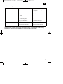
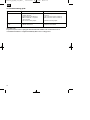
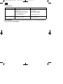
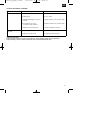
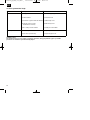
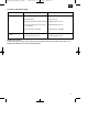
Fehler Mögliche Ursachen Beseitigung
Motor läuft nicht an a) Kein Strom im Stecker
b) Kabel defekt
c) Schalter Stecker Kombination
defekt
d) Anschlüsse am Motor oder
Kondensator gelöst
e) zu große Arbeitstiefe
a) Leitung und Sicherung
überprüfen
b) überprüfen
c) durch Kundendienstwerkstatt
d) durch Kundendienstwerkstatt
e) Arbeitstiefe verringern
Motorleistung lässt nach a) Zu harter Boden
b) Messer stark abgenutzt
a) Arbeitstiefe korrigieren
b) Hackmesser auswechseln
10. Fehlersuchplan
Wichtiger Hinweis!
Um den Motor zu schützen, ist dieser mit einem Thermoschalter ausgestattet, der bei Überlastung
abschaltet und nach einer kurzen Abkühlphase wieder automatisch einschaltet!
Anleitung_E_EBH_750_SPK7:_ 28.10.2010 11:05 Uhr Seite 11

12
GB
Important!
When using equipment, a few safety precautions
must be observed to avoid injuries and damage.
Please read the complete operating manual with due
care. Keep this manual in a safe place, so that the
information is available at all times. If you give the
equipment to any other person, give them these
operating instructions as well.
We accept no liability for damage or accidents which
arise due to non-observance of these instructions
and the safety information.
1. Safety information
Please refer to the booklet included in delivery for the
safety instructions.
CAUTION!
Read all safety regulations and instructions.
Any errors made in following the safety regulations
and instructions may result in an electric shock, fire
and/or serious injury.
Keep all safety regulations and instructions in a
safe place for future use.
2. Layout (Fig. 1-3, 12)
1. Top push bar
2. Bottom push bar
3. Motor unit
4. Hoe blades
5. Cable strain-relief clamp
6. Two-hand safety switch
6a Two-point switch
6b Selector lever
6c Power plug
7. Cable securing clips
8. 2x screw for installing the top push bar
9. 2x screw for installing the bottom push bar
10. 2x screw for installing 2-hand safety switch
11. 2x nut M6
12. 2x wing nut
3. Proper use
The machine is designed for digging soil (for
example garden beds). Be sure to observe the
restrictions in the safety instructions.
The machine is to be used only for its prescribed
purpose. Any other use is deemed to be a case of
misuse. The user / operator and not the
manufacturer will be liable for any damage or injuries
of any kind caused as a result of this.
Please note that our equipment has not been
designed for use in commercial, trade or industrial
applications. Our warranty will be voided if the
machine is used in commercial, trade or industrial
businesses or for equivalent purposes.
The operating instructions as supplied by the
manufacturer must be kept and referred to in order to
ensure that the machine is properly used and
maintained. The instructions contain valuable
information on operating, maintenance and servicing
conditions.
For safety reasons, the machine may not be used as
a drive unit for other work tools or tool sets of any
kind.
4. Technical data
Voltage 230V ~ 50Hz
Power input 750 W
Working width 30 cm
Hoe diameter 22 cm
Idle speed 400 rpm
Number of blades 4 pieces
LpA noise level 70 dB(A)
LWA peak noise level 93 dB(A)
Vibration at the handlebars ahv < 2.5 m/s2
Anleitung_E_EBH_750_SPK7:_ 28.10.2010 11:05 Uhr Seite 12

13
GB
Keep the noise emissions and vibrations to a
minimum.
Only use appliances which are in perfect working
order.
Service and clean the appliance regularly.
Adapt your working style to suit the appliance.
Do not overload the appliance.
Have the appliance serviced whenever
necessary.
Switch the appliance off when it is not in use.
Wear protective gloves.
5. Before starting the equipment
Assembly (Fig. 4-11)
앬Place the motor unit and the push bars on the
ground in order (Fig. 4).
앬Important. Do not forget to slide the cable strain-
relief clamp (Fig. 6/Item 5) over the bottom push
bar.
앬Slide the bottom push bar on to the push bar
holder and secure the two components to each
other (Fig. 5).
앬Now secure the top push bar to the bottom push
bar (Fig. 6).
앬Install the 2-hand safety switch as shown in Fig.
7-10.
앬Secure the cable using the supplied cable
securing clips (Fig. 11/7)
Power supply
The machine can be connected to any light socket-
outlet (with 230 Volt alternating current). However,
the socket outlet must have an earthing contact
protected by a 16 A circuit breaker. Additionally, a
residual current device (RCD) circuit-breaker with
max. 30 mA must be used!
Power cable for the device
Please only use power cables that are not damaged.
The total length of the power cable should not
exceed 50 meters; going beyond this distance will
reduce the power output of the electric motor. The
power cable must have a cross-section of 3 x 1.5
mm2. The insulating sheath of such machines is
frequently damaged. Some of the causes for this are:
- Cracking due to old age of the insulation
- Kinking caused by improper fastening or
guidance of the power cable
Even though power cables with damaged insulation
sheaths pose a lethal hazard, some people still use
them. Do not make this mistake! Cables, plugs and
socket couplers must meet the following
requirements listed below. Power cables used to
connect machines must have a rubber insulation
sheath.
The power cables must, at the very minimum, be of
type HO5RN-F and 3-stranded. The cable type must
be printed somewhere on the power cable. Only
purchase power cables that are marked! Plugs and
socket couplers for the power cables must be made
from rubber and splash-proof. There is a limit to how
long power cables can be. Longer power cables
require larger conductor cross-sections. Power
cables and connecting lines must be regularly
checked for damage. Ensure that the lines are de-
energized before checking them. Completely unwind
the power cable. Also check power cable entry
points, plugs and socket couplers for kinks.
6. Operation
6.1 Starting up
Connect the machineʼs power supply cable to the
plug (Fig. 12/Item 6c) and secure the power cable
with the strain-relief clamp (Fig 12/Item 5).
Important! To prevent accidental start-up of the
machine, the push-bar is equipped with a two-point
switch (Fig. 13/Item 6a) which must be pressed
before the lever switch (Fig. 13/Item 6b) can be
pressed. If the lever switch is released, the machine
switches off. Repeat this process several times so
that you are sure that your machine functions
properly. Before you perform any repair or
maintenance work on the machine, ensure that the
hoe blades are not rotating and that the power
supply is disconnected.
Always ensure that a safe distance (provided by the
long handles) is maintained between the machine
and the user. Be especially careful when changing
direction on slopes and inclines. Maintain a solid
footing and wear sturdy, non-slip footwear and long
trousers. Always work along the incline (not up and
down).
Use special caution when backing up and pulling the
machine (tripping hazard).
Anleitung_E_EBH_750_SPK7:_ 28.10.2010 11:05 Uhr Seite 13

14
GB
6.2 Tips for proper working
Place the machine in front of the area you wish to
hoe and hold it securely on the push bar before you
switch on the machine. Guide the hoe blades over
the area.
To achieve cleanly hoed soil always ensure that you
guide the machine in straight lines wherever
possible. Insodoing, the aeration swaths should
always overlap each other by a few centimeters in
order to avoid bare strips.
Switch off the motor promptly when you arrive at the
end of the area you wished to hoe. The motor must
be switched off when you raise the machine (for
example to change direction).
Keep the underside of the machine clean and
remove soil deposits. Deposits make it more difficult
to start the machine and decrease the working depth.
Work perpendicular to the slop on inclined areas.
The machine must be switched off and the mains
cable disconnected before you make any checks on
the hoe blades.
Prior to sowing, we recommend one of the methods
of preparation as shown in Figure 14.
Method A:
First hoe the ground row by row, then carry out the
hoeing a second time but at an angle of 90 degrees.
Method B:
First hoe the ground row by row, then carry out the
hoeing a second time but with overlapping paths.
Important!
The hoe blades will continue to rotate for a few
seconds after the motor is switched off. Never
attempt to manually stop them. In the event that the
rotating hoe blade strikes an object, immediately
switch off the machine and wait for the hoe blades to
come to a complete stop. Then inspect the condition
of the hoe blades. Replace any parts that are
damaged.
Lay the power cable on the ground in front of the
outlet in a figure 8. Work away from the outlet or
cable and ensure that the power cable always trails
in the hoed soil which will prevent the hoe blades
from traveling over the cable.
7. Replacing the power cable
If the power cable for this equipment is damaged, it
must be replaced by the manufacturer or its after-
sales service or similarly trained personnel to avoid
danger.
8. Cleaning, maintenance and ordering
of spare parts
Maintenance and cleaning work on the machine as
well as removal of the safety devices may only be
performed when the motor is switched off and the
power cable has been pulled.
8.1 Cleaning
Keep all safety devices, air vents and the motor
housing free of dirt and dust as far as possible.
Wipe the equipment with a clean cloth or blow it
with compressed air at low pressure.
We recommend that you clean the device
immediately each time you have finished using it.
Clean the equipment regularly with a moist cloth
and some soft soap. Do not use cleaning agents
or solvents; these could attack the plastic parts
of the equipment. Ensure that no water can seep
into the device.
8.2 Replace the hoe blades
For safety reasons, we recommend having the hoe
blades replaced by an authorized professional (see
address on warranty certificate).
Important!
Wear working gloves. Use only genuine spare parts
since otherwise the function and safety of the
machine cannot be guaranteed.
8.3 Maintenance
Ensure that all mounting components (i.e. screws,
bolts, nuts etc.) are always tightened so that the
machine can be safely operated at all times.
Store the device in a dry room. All the metal parts
should be cleaned and then oil to ensure that they
provide a long life. For best results, clean the plastic
parts of the machine with a brush or rag. Do not use
any solvents to remove dirt.
At the end of the season, perform a general
inspection of the machine and remove any deposits
which may have accumulated. At the start of each
season, ensure that you check the condition of the
machine. If repairs are necessary, please contact
one of our customer service centers (see address on
warranty certificate).
Ensure that all moving parts are kept running
smoothly (lubricate if necessary).
Checking the gear oil (Fig. 15)
The oil drainage screw is fitted to the right side of the
gear box. If necessary, dismantle the blades.
Place the electric hoe on its left side to ensure
that no dirt or foreign bodies get into the gears.
Anleitung_E_EBH_750_SPK7:_ 28.10.2010 11:05 Uhr Seite 14

15
GB
Use a 5 mm Allen key to open the oil drainage
screw and let the oil drain off into a container.
Refill the equipment with new and high-grade
motor lubricating oil.
Screw the oil drainage screw back in place.
Transport
Important. Switch off the motor before transporting
the equipment. If you pull the electric hoe over hard
ground, the blades and the equipment may be
damaged even with the motor switched off. Make sure
that the equipment does not come into contact with
such a surface.
8.4 Ordering replacement parts
Please quote the following data when ordering
replacement parts:
Type of machine
Article number of the machine
Identification number of the machine
Replacement part number of the part required
For our latest prices and information please go to
www.isc-gmbh.info
9. Disposal and recycling
The unit is supplied in packaging to prevent its being
damaged in transit. This packaging is raw material
and can therefore be reused or can be returned to
the raw material system.
The unit and its accessories are made of various
types of material, such as metal and plastic.
Defective components must be disposed of as
special waste. Ask your dealer or your local council.
Anleitung_E_EBH_750_SPK7:_ 28.10.2010 11:05 Uhr Seite 15

GB
16
10. Troubleshooting guide
Fault Possible causes Remedy
Motor does not start a) No power at the plug
b) Cable defective
c) Switch/plug block defective
d) Motor terminals or capacitor
disconnected
e) excessive working depth
a) Check the power cable and fuse
b) Check
c) By customer service workshop
d) By customer service workshop
e) Reduce working depth
Motor performance
drops
a) Soil too hard
b) Blades badly worn
a) Correct working depth
b) Replace hoe blades
Important note!
For protection, the motor is equipped with a thermal switch which cuts out when the motor is
overloaded and switches on again automatically after a short cooling period.
Anleitung_E_EBH_750_SPK7:_ 28.10.2010 11:05 Uhr Seite 16

F
17
Attention !
Lors de lʼutilisation dʼappareils, il faut respecter
certaines mesures de sécurité afin dʼéviter des
blessures et dommages. Veuillez donc lire
attentivement ce mode dʼemploi. Conservez-le bien
de façon à pouvoir disposer à tout moment de ces
informations. Si lʼappareil doit être remis à dʼautres
personnes, remettez-leur aussi ce mode dʼemploi.
Nous déclinons toute responsabilité pour les
accidents et dommages dus au non-respect de ce
mode dʼemploi et des consignes de sécurité.
1. Consignes de sécurité
Vous trouverez les consignes de sécurité
correspondantes dans le petit manuel ci-joint.
AVERTISSEMENT !
Veuillez lire toutes les consignes de sécurité et
instructions.
Tout non-respect des consignes de sécurité et
instructions peut provoquer une décharge électrique,
un incendie et/ou des blessures graves.
Conservez toutes les consignes de sécurité et
instructions pour une consultation ultérieure.
2. Description de lʼappareil (fig. 1-3, 12)
1. Guidon supérieur
2. Guidon inférieur
3. Unité moteur
4. Couteau hacheur
5. Déchargeur pour câble
6. 2 interrupteurs de sécurité manuels
6a Interrupteur à deux positions
6b Levier de commutation
6c Fiche de raccordement au réseau
7. Clip de fixation du câble
8. 2x vis pour montage du guidon supérieur
9. 2x vis pour montage du guidon inférieur
10. 2x vis de montage pour l’interrupteur de sécurité
2 mains
11. 2x écrous M6
12. 2x écrous à oreilles
3. Utilisation conforme à l’affectation
L’appareil est destiné à retourner la terre (par ex.
plates-bandes). Veuillez absolument respecter les
limites indiquées dans les consignes de sécurité
La machine doit exclusivement être employée
conformément à son affectation. Chaque utilisation
allant au-delà de cette affectation est considérée
comme non conforme. Pour les dommages en
résultant ou les blessures de tout genre, le
producteur décline toute responsabilité et
lʼopérateur/lʼexploitant est responsable.
Veillez au fait que nos appareils, conformément à
leur affectation, nʼont pas été construits, pour être
utilisés dans un environnement professionnel,
industriel ou artisanal. Nous déclinons toute
responsabilité si lʼappareil est utilisé
professionnellement, artisanalement ou dans des
sociétés industrielles, tout comme pour toute activité
équivalente.
Le respect du mode d’emploi joint par le producteur
est la condition primordiale prélable à une utilisation
conforme de l’appareil. Le mode d’emploi comprend
aussi les conditions de service, de maintenance et
d’entretien.
Pour des raisons de sécurité, l’appareil ne doit pas
être utilisé comme module d’entraînement pour
d’autres outils de travail et outillages de quelque
forme que ce soit.
4. Caractéristiques techniques
Tension du réseau : 230V ~ 50 Hz
Puissance absorbée : 750 W
Largeur de travail : 30 cm
Ø du crochet : 22 cm
Vitesse de rotation de marche à vide : 400 tr/mn
Nombre de lames : 4 pièces
Niveau de pression acoustique LpA: 70 dB(A)
Niveau acoustique LWA : 93 dB(A)
Vibration du guidon ahv < 2,5 m/s2
Anleitung_E_EBH_750_SPK7:_ 28.10.2010 11:05 Uhr Seite 17

F
18
Limitez le niveau sonore et les vibrations à un
minimum !
Utilisez exclusivement des appareils en excellent
état.
Entretenez et nettoyez l’appareil régulièrement.
Adaptez votre façon de travailler à l’appareil.
Ne surchargez pas l’appareil.
Faites contrôler l’appareil le cas échéant.
Mettez l’appareil hors circuit lorsque vous ne
l’utilisez pas.
Portez des gants.
5. Avant la mise en service
Montage (fig. 4-11)
앬Placez l’unité moteur et le guidon l’un derrière
l’autre sur le sol (fig. 4).
앬Attention ! N’oubliez pas de glisser le
déchargeur pour câble (fig. 6/pos. 5) par-dessus
le guidon inférieur.
앬Glissez le guidon inférieur sur le support du
guidon et vissez-les ensemble (fig. 5).
앬Assemblez maintenant le guidon inférieur et le
guidon supérieur (fig. 6).
앬Montez les 2 interrupteurs de sécurité 2 mains
comme indiqué en fig. 7 à 10.
앬Fixez le câble avec le clip de fixation pour le
câble fourni (fig. 11/7).
Branchement électrique
L’appareil peut être raccordé à chaque prise de
courant d’éclairage (de 230 Volt courant alternatif).
Seules cependant des prises à contact de protection
sont admises, il faut prévoir pour leur protection par
fusibles un disjoncteur automatique de protection
pour 16A. En outre, il faut coupler un interrupteur
différentiel (RCD) de 30 mA en amont !
Câble de raccordement de l’appareil
N’utilisez que des câbles de raccordement pour
l’appareil n’étant pas endommagés. Le câble de
raccordement de l’appareil ne doit pas être trop long
(max. 50 m), car autrement cela réduit la puissance
du moteur électrique. La section transversale du
câble de raccordement de l’appareil doit s’élever à 3
x 1,5mm2. Les câbles de raccordement souffrent
souvent d’endommagement de leur isolation.
Les causes en sont entre autres:
앬des fissures par vieillissement de l’isolation
앬des pliures dues à la fixation ou au guidage non
conforme du câble de raccordement
Si de tels câbles de raccordement sont utilisés alors
que leur isolation est endommagée, ils représentent
un danger de mort. Les câbles, fiches et prises
d’accouplement doivent répondre aux conditions de
la liste suivante. Les câbles de raccordement des
appareils doivent avoir une isolation en caoutchouc.
Les câbles de raccordement doivent au moins être
de type H05RN-F et avoir 3 brins. Une impression de
la désignation de type sur le câble de raccordement
est obligatoire. N’achetez que des câbles de
raccordement dûment marqués ! Les fiches et prises
d’accouplement aux câbles de raccordement soivent
être en caoutchouc et être protégés contre les
éclaboussures d’eau. Les câbles de raccordement
des appareils ne doivent pas être trop longs. Des
câbles de raccordement longs doivent avoir une
section de conducteur plus importante.
Les câbles de raccordement et conduites de
raccordement doivent être contrôlées régulièrement
quant à d’éventuels dommages. Veillez à ce que les
câbles soient déconnectés pendant le contrôle.
Déroulez complètement le câble de raccordement de
l’appareil. Contrôlez aussi les introductions des
câbles de raccordement, au niveau des fiches et des
prises d’accouplement, quant à d’éventuels plis.
6. Commande
6.1 Mise en service
Raccordez le câble de l’appareil avec la fiche (fig. 12/
pos. 6c) et assurez le câble avec la détente du collier
(fig. 12/pos. 5).
Attention ! Pour éviter une mise en marche
intempestive du scarificateur, le guidon est doté d’un
interrupteur à deux positions (fig. 13/pos. 6a) sur
lequel il faut appuyer avant de pouvoir actionner le
levier de commande (fig. 13/ pos. 6b). L’appareil se
met hors circuit dès qu’on lâche le levier de
commande. Répétez cette opération plusieurs fois
afin de vous assurer que l’appareil fonctionne
correctement. Avant d’entreprendre des réparations
ou des travaux de maintenance, vous devez vous
assurer que les couteaux hacheurs ne tournent pas et
que l’appareil n’est pas branché.
L’espace de sécurité entre l’appareil et l’utilisateur,
qui correspond au guidon, doit toujours être respecté.
Montrez-vous particulièrement prudent en cas de
changement de direction devant un remblai ou un
talus. Veillez à vous tenir de façon sûre, portez des
chaussures à semelles anti-dérapantes et
agrippantes et des pantalons longs. Travaillez
toujours transversalement par rapport à la pente.
Faites particulièrement attention dans vos
mouvements en arrière et lorsque vous tirez le
scarificateur, risque de trébuchement !
Anleitung_E_EBH_750_SPK7:_ 28.10.2010 11:05 Uhr Seite 18

F
19
6.2 Indications pour une bonne utilisation
Placez l’appareil devant la surface à travailler et
maintenez-le fermement par le guidon avant de le
mettre en marche.
Passez les couteaux hacheurs au-dessus de la
surface à travailler.
Essayez si possible de garder une trajectoire
constante afin d’arriver à traiter la surface
régulièrement. Les bords de ces pistes doivent alors
se chevaucher de quelques centimètres pour
qu’aucune bande ne reste sans aération.
Arrêtez le moteur à temps quand vous arrivez à la fin
d’une surface à travailler. Quand l’appareil est
soulevé (pour un changement de direction, par ex.), il
faut éteindre le moteur.
Veillez à toujours garder propre le dessous de
l’appareil et à retirer absolument tous les dépôts de
terre. Les dépôts de terre rendent le processus de
démarrage plus difficile et altèrent le travail en
profondeur.
Sur les talus, mettez-vous en position transversale à
la pente. Avant tout contrôle des couteaux, coupez le
moteur et débranchez le câble du réseau.
Pour la préparation des semences, nous
recommandons de procéder comme indiqué dans la
figure 14.
Procédure A :
Travaillez tout d’abord voie par voie, ensuite une
deuxième fois en vous déplaçant de 90 degrés.
Procédure B :
Travaillez d’abord voie par voie, ensuite une
deuxième fois, mais avec des parcours qui se
chevauchent.
Attention !
Les couteaux continuent à tourner quelques
secondes encore après l’arrêt du moteur. Ne tentez
jamais de les arrêter. Au cas où les couteaux en
mouvement buttent contre un objet, mettez l’appareil
hors circuit et attendez que les couteaux
s’immobilisent complètement. Contrôlez ensuite l’état
des couteaux. Si ceux-ci sont endommagés, ils
doivent être changés.
Posez le câble de raccordement de l’appareil en
forme de boucle devant la prise utilisée, sur la terre.
Travaillez en vous éloignant de la prise et du câble et
en veillant à ce que le câble de raccordement se
trouve toujours sur le sol labouré afin d’être certain de
ne pas passer par-dessus avec les couteaux.
7. Remplacement de la ligne de
raccordement réseau
Si la ligne de raccordement réseau de cet appareil
est endommagée, il faut la faire remplacer par le
producteur ou son service après-vente ou par une
personne de qualification semblable afin dʼéviter tout
risque.
8. Nettoyage, maintenance et
commande de pièces de rechange
Ne procédez aux travaux de maintenance, au
nettoyage ou à l’enlèvement des dispositifs de
protection de l’appareil qu’après avoir arrêté le
moteur et l’avoir débranché.
8.1 Nettoyage
Maintenez les dispositifs de protection, les fentes
à air et le carter de moteur aussi propres (sans
poussière) que possible. Frottez lʼappareil avec
un chiffon propre ou soufflez dessus avec de lʼair
comprimé à basse pression.
Nous recommandons de nettoyer lʼappareil
directement après chaque utilisation.
Nettoyez lʼappareil régulièrement à lʼaide dʼun
chiffon humide et un peu de savon. Nʼutilisez
aucun produit de nettoyage ni détergeant ; ils
pourraient endommager les pièces en matières
plastiques de lʼappareil. Veillez à ce quʼaucune
eau nʼentre à lʼintérieur de lʼappareil.
8.2 Changement des couteaux hacheurs
Pour des raisons de sécurité, nous recommandons
de confier le remplacement des couteaux à un(e)
spécialiste dûment autorisé(e) (voir adresse sur le
certificat de garantie).
Attention !
Portez des gants de travail !
N’utilisez que des pièces détachées d’origine, faute
de quoi, le fonctionnement et la sécurité ne seraient
pas garantis.
8.3 Maintenance
Faites en sorte que les éléments de fixation (vis,
écrous etc.) restent toujours bien fixés afin de pouvoir
utiliser l’appareil en toute sécurité.
Stockez l’appareil dans une salle sèche. Pour leur
assurer une longue durée de vie, les pièces
métalliques doivent être nettoyées et huilées.
Nettoyez les parties en plastiques de l’appareil avec
des brosses ou des chiffons si possible. N’utilisez
aucun solvant pour éliminer les salissures.
Anleitung_E_EBH_750_SPK7:_ 28.10.2010 11:05 Uhr Seite 19

F
20
A la fin de la saison, effectuez un contrôle général de
l’appareil et retirez tous les dépôts accumulés.
En tout début de chaque saison, vérifier
impérativement l’état de l’appareil. Pour vos
réparations, adressez-vous à notre service après-
vente (voir adresse sur le certificat de garantie).
Maintenez toutes les pièces amovibles facilement
amovibles (le cas échéant, graisser).
Contrôle de l’huile pour boîtes de vitresses (fig.
15)
Le bouchon de vidange d’huile se trouve sur le côté
droit de la boîte d’engrenages. Démontez les lames
au besoin.
Basculez la bineuse électrique sur le côté
gauche, afin d’empêcher que des impuretés ou
des corps étranger ne s’incrustent dans la
transmission.
Ouvrez le bouchon de vidange d’huile à l’aide
d’une clé à six pans creux 5 mm et faites couler
l’huile dans un récipient.
Remplissez de nouvelle huile à moteur de bonne
qualité jusqu’au bord supérieur.
Revissez le bouchon de vidange d’huile.
Transport
Attention ! Avant de transporter la machine, mettez
le moteur hors circuit. Les lames et la machine
peuvent s’endommager même lorsque le moteur est
hors circuit, si vous tirez la bineuse électrique sur un
sol solide. Evitez que la machine touche un tel sol.
8.4 Commande de pièces de rechange :
Pour les commandes de pièces de rechange,
veuillez indiquer les références suivantes:
Type de lʼappareil
No. dʼarticle de lʼappareil
No. dʼidentification de lʼappareil
No. de pièce de rechange de la pièce requise
Vous trouverez les prix et informations actuelles à
ʼadresse www.isc-gmbh.info
9. Mise au rebut et recyclage
Lʼappareil se trouve dans un emballage permettant
dʼéviter les dommages dus au transport. Cet
emballage est une matière première et peut donc
être réutilisé ultérieurement ou être réintroduit dans
le circuit des matières premières.
Lʼappareil et ses accessoires sont en matériaux
divers, comme par ex. des métaux et matières
plastiques. Eliminez les composants défectueux
dans les systèmes dʼélimination des déchets
spéciaux. Renseignez-vous dans un commerce
spécialisé ou auprès de lʼadministration de votre
commune !
Anleitung_E_EBH_750_SPK7:_ 28.10.2010 11:05 Uhr Seite 20
La pagina sta caricando ...
La pagina sta caricando ...
La pagina sta caricando ...
La pagina sta caricando ...
La pagina sta caricando ...
La pagina sta caricando ...
La pagina sta caricando ...
La pagina sta caricando ...
La pagina sta caricando ...
La pagina sta caricando ...
La pagina sta caricando ...
La pagina sta caricando ...
La pagina sta caricando ...
La pagina sta caricando ...
La pagina sta caricando ...
La pagina sta caricando ...
La pagina sta caricando ...
La pagina sta caricando ...
La pagina sta caricando ...
La pagina sta caricando ...
La pagina sta caricando ...
La pagina sta caricando ...
La pagina sta caricando ...
La pagina sta caricando ...
La pagina sta caricando ...
La pagina sta caricando ...
La pagina sta caricando ...
La pagina sta caricando ...
La pagina sta caricando ...
La pagina sta caricando ...
La pagina sta caricando ...
La pagina sta caricando ...
La pagina sta caricando ...
La pagina sta caricando ...
La pagina sta caricando ...
La pagina sta caricando ...
La pagina sta caricando ...
La pagina sta caricando ...
La pagina sta caricando ...
La pagina sta caricando ...
La pagina sta caricando ...
La pagina sta caricando ...
La pagina sta caricando ...
La pagina sta caricando ...
La pagina sta caricando ...
La pagina sta caricando ...
La pagina sta caricando ...
La pagina sta caricando ...
-
 1
1
-
 2
2
-
 3
3
-
 4
4
-
 5
5
-
 6
6
-
 7
7
-
 8
8
-
 9
9
-
 10
10
-
 11
11
-
 12
12
-
 13
13
-
 14
14
-
 15
15
-
 16
16
-
 17
17
-
 18
18
-
 19
19
-
 20
20
-
 21
21
-
 22
22
-
 23
23
-
 24
24
-
 25
25
-
 26
26
-
 27
27
-
 28
28
-
 29
29
-
 30
30
-
 31
31
-
 32
32
-
 33
33
-
 34
34
-
 35
35
-
 36
36
-
 37
37
-
 38
38
-
 39
39
-
 40
40
-
 41
41
-
 42
42
-
 43
43
-
 44
44
-
 45
45
-
 46
46
-
 47
47
-
 48
48
-
 49
49
-
 50
50
-
 51
51
-
 52
52
-
 53
53
-
 54
54
-
 55
55
-
 56
56
-
 57
57
-
 58
58
-
 59
59
-
 60
60
-
 61
61
-
 62
62
-
 63
63
-
 64
64
-
 65
65
-
 66
66
-
 67
67
-
 68
68


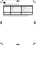
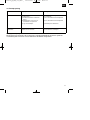
Pattfield E-EBH 750 Istruzioni per l'uso
- Tipo
- Istruzioni per l'uso
- Questo manuale è adatto anche per
in altre lingue
- français: Pattfield E-EBH 750 Mode d'emploi
- Deutsch: Pattfield E-EBH 750 Bedienungsanleitung
- Nederlands: Pattfield E-EBH 750 Handleiding
- slovenčina: Pattfield E-EBH 750 Návod na používanie
- svenska: Pattfield E-EBH 750 Bruksanvisningar
- română: Pattfield E-EBH 750 Instrucțiuni de utilizare
Altri documenti
-
Einhell Blue BG-RT 1340 M Istruzioni per l'uso
-
EINHELL GC-RT 7530 Manuale del proprietario
-
-
 Einhell Royal RVL 1200 Manuale del proprietario
-
-
Einhell Red RG-ES 1639 Istruzioni per l'uso
-
Einhell Blue BG-SA 1231 Manuale del proprietario
-
-
 Einhell Red RG-EM 1742 Manuale del proprietario
-

