Fadini elpro-s50-T1.EFO Instructions Manual
- Tipo
- Instructions Manual

Elpro S50-T1.EFO
- PREDISPOSTO PER SEMAFORO A 3 LUCI
- AUTOMATICO O SEMIAUTOMATICO
- PREDISPOSIZIONE PER OROLOGIO ESTERNO
- FUNZIONE PASSO-PASSO
- UOMO PRESENTE
- PRE-SET FOR A TRAFFIC LIGHT WITH 3 LAMPS
- AUTOMATIC OR SEMI-AUTOMATIC
- PRE-SET FOR EXTERNAL TIME CLOCK
- STEP BY STEP FUNCTION
- DEADMAN (HOLD-ON-SWITCHED) CONTROL
- PREPARE POUR FEU DE CIRCULATION A 3 VOYANTS
- AUTOMATIQUE OU SEMI-AUTOMATIQUE
- PREPARE POUR HORLOGE EXTERNE
- FONCTION PAS-PAS
- HOMME MORT
- FÜR AMPEL MIT 3 LICHTERN VORGESEHEN
- AUTOMATISCH ODER HALBAUTOMATISCH
- FÜR EXTERNE UHR VORGESEHEN
- SCHRITT FÜR SCHRITT FUNKTION (IMPULSBETRIEB)
- TOTMANN-BETRIEB
PROGRAMMATORE ELETTRONICO MONOFASE
PER UN DISSUASORE A SCOMPARSA ANTITERRORISMO TALOS M50
SINGLE-PHASE ELECTRONIC CONTROLLER
FOR ONE TALOS M50 ANTI-TERRORISM RETRACTABLE BOLLARDS
PROGRAMMATEUR ÉLECTRONQUE MONOPHASÉ
POUR UNE BORNE ESCAMOTABLE ANTI-TERRORISME TALOS M50
EINPHASIGE ELEKTRONISCHE STEUERUNG
FÜR EINEN TALOS M50 ANTI-TERROR VERSENKBARE POLLER
IT
GB
FR
DE
IT
GB
FR
DE
Dis. N. 9318 Via Mantova, 177/A - 37053 Cerea (VR) Italy
Ph. +39 0442 330422 Fax +39 0442 331054
[email protected] - www.fadini.net

PROGRAMMATORE PER DISSUASORI A SCOMPARSA ANTITERRORISMO
TALOS M50
Elpro S50-T1.EFO
IT
AVVERTENZE GENERALI PER LA SICUREZZA DELLE PERSONE
GRAZIE
Vi ringraziamo per aver deciso di acquistare un prodotto Fadini.
Vi invitiamo a leggere attentamente queste istruzioni prima di
iniziare a usare il dispositivo. Le istruzioni contengono
informazioni importanti che vi aiuteranno a trarre il meglio da
questo dispositivo e vi garantiranno altresì sicurezza in fase di
installazione, uso e manutenzione del dispositivo. Conservare
questo manuale in un luogo pratico, in modo da poterlo
sempre consultare e garantire un utilizzo sicuro e adeguato del
dispositivo.
INTRODUZIONE
Questa automazione è stata progettata per un utilizzo
esclusivo per quanto indicato in questo libretto, con gli
accessori di sicurezza e di segnalazione minimi richiesti e con i
dispositivi Fadini. □ Qualsiasi altra applicazione non
espressamente indicata in questo libretto potrebbe provocare
disservizi o danni a cose e persone. □ Meccanica Fadini S.r.l. non
è responsabile per eventuali danni derivati da usi impropri e
non specicatamente indicati in questo libretto; non risponde
inoltre di malfunzionamenti derivati dall'uso di materiali e/o
accessori non indicati dalla ditta stessa. □ La ditta costruttrice si
riserva di apportare modiche ai propri prodotti senza
preavviso. □ Tutto quanto non espressamente indicato
inquesto manuale di istruzioni non è permesso.
PRIMA DELL'INSTALLAZIONE
Prima di qualsiasi intervento valutare l'idoneità dell'ingresso da
automatizzare, nonché la sua condizione e la struttura. □
Accertarsi che non si verichino situazioni di impatto,
schiacciamento, cesoiamento, convogliamento, taglio,
uncinamento e sollevamento, tali da poter pregiudicare la
sicurezza delle persone. □ Non installare il prodotto nelle
vicinanze di fonti di calore ed evitare il contatto con sostanze
inammabili. □ Tenere lontano dalla portata di bambini
qualsiasi dispositivo (trasmettitori, lettori di prossimità,
selettori, ecc.) atto ad avviare l'automazione. □ Il transito nella
zona di luce di passaggio deve avvenire unicamente con
l'automazione ferma. □ Non consentire a bambini e/o persone
di stazionare nei pressi dell'impianto con l'automazione in
movimento. □ Per garantire un livello adeguato di sicurezza
dell'impianto è necessario utilizzare fotocellule, bordi sensibili,
spire magnetiche e sensori di presenza per mettere in sicurezza
l'intera area interessata al movimento del cancello. □ Servirsi di
strisce giallo-nere o di adeguati segnali per identicare i punti
pericolosi dell'installazione. □ Togliere sempre l'alimentazione
elettrica all'impianto se si eettuano interventi di
manutenzione e/o pulizia. □ In caso di asportazione
dell’attuatore, non tagliare i li elettrici, ma toglierli dalla
morsettiera allentando le viti di serraggio dentro la scatola di
derivazione.
INSTALLAZIONE
L'intera installazione deve essere eettuata da personale
tecnico qualicato, in osservanza della Direttiva Macchine
2006/42/CE e in particolare le norme EN 12445 ed EN 12453. □
Vericare la presenza, a monte dell'impianto, di un interruttore
di linea 230 V - 50 Hz magneto-termico dierenziale da 0,03 A.
□ Utilizzare corpi di prova idonei per le prove di funzionamento
nella rilevazione della presenza, in prossimità o interposti, ai
dispositivi di sicurezza come fotocellule, bordi sensibili, ecc. □
Eseguire una attenta analisi dei rischi, utilizzando appositi
strumenti di rilevazione di impatto e schiacciamento del bordo
principale di apertura e chiusura, secondo quanto indicato
nella normativa EN 12445. □ Individuare la soluzione più
indicata per eliminare o ridurre tali rischi. □ Nel caso in cui il
cancello da automatizzare fosse dotato di un ingresso
pedonale, è opportuno predisporre l'impianto in maniera tale
da interdire il funzionamento del motore quando l'ingresso
pedonale è utilizzato. □ Fornire indicazioni sulla presenza
dell'impianto realizzato con l'applicazione di targhe
segnaletiche con marcatura CE sul cancello. □ L'installatore è
tenuto ad informare ed istruire l'utilizzatore nale circa l'uso
corretto dell'impianto; ciò avviene rilasciandogli una
documentazione rmata denita fascicolo tecnico,
comprensiva di: schema e componenti dell'impianto, analisi
dei rischi, verica degli accessori di sicurezza, verica delle
forze di impatto e segnalazione dei rischi residui.
INDICAZIONI PER L'UTILIZZATORE FINALE
L'utilizzatore nale è tenuto a prendere visione e ricevere
informazioni unicamente per quanto concerne il
funzionamento dell'impianto e diviene lui stesso responsabile
del corretto uso. □ Deve stipulare un contratto di
manutenzione ordinaria e straordinaria (su chiamata) con
l'installatore/manutentore.□ Qualsiasi intervento di
riparazione deve essere eettuato solo da personale tecnico
qualicato. □ Conservare sempre il presente manuale di
istruzioni.
AVVERTENZE PER IL BUON FUNZIONAMENTO
DELL'IMPIANTO
Per una resa ottimale dell’impianto nel tempo e secondo le
normative di sicurezza, è necessario eseguire una corretta
manutenzione e un adeguato monitoraggio dell’intera
installazione per l’automazione, per le apparecchiature
elettroniche installate e anche per i cablaggi ad esse eettuate.
□ Tutta l’installazione deve essere eseguita da personale
tecnico qualicato, compilando il documento di verica e
collaudo ed il registro di manutenzione indicato nel libretto
normative di sicurezza (da richiedere o scaricare dal sito
www.fadini.net/supporto/downloads). □ Per l'automazione è
consigliato un controllo di manutenzione almeno ogni 6 mesi,
mentre per apparecchiature elettroniche e sistemi di sicurezza
un controllo mensile di manutenzione. □ Meccanica Fadini S.r.l.
non è responsabile dell'eventuale inosservanza della buona
tecnica di installazione e/o del non corretto mantenimento
dell'impianto.
SMALTIMENTO DEI MATERIALI
Gli involucri dell’imballo come cartone, nylon, polistirolo, ecc.
possono essere smaltiti eettuando la raccolta dierenziata
(previa verica delle normative vigenti nel luogo
dell'installazione in materia di smaltimento riuti). Elementi
elettrici, elettronici e batterie possono contenere sostanze
inquinanti: rimuovere e adare tali componenti a ditte
specializzate nel recupero dei riuti, come indicato nella
direttiva 2012/19/UE. Vietato gettare nei riuti materiali nocivi
per l’ambiente.
Meccanica Fadini S.r.l.
Direttore Responsabile
DICHIARAZIONE DI CONFORMITÀ UE
Fabbricante: Meccanica Fadini S.r.l.
Indirizzo: Via Mantova, 177/A - 37053 Cerea - VR - Italy
dichiara sotto la propria responsabilità che:
Programmatore elettronico ELPRO S50-T1.EFO
è conforme alla pertinente normativa di armonizzazione dell’Unione:
- Direttiva Compatibilità Elettromagnetica 2014/30/UE
- Direttiva Bassa Tensione 2014/35/UE
Cerea, 13/10/2017
2

PROGRAMMATORE PER DISSUASORI A SCOMPARSA ANTITERRORISMO
TALOS M50
IT
3
58
56
1 4 5 678910
ELPRO S20
T2
TEMPO DI PAUSA
1 s - 180 s
T1
TEMPO DI LAVORO
1 s - 22 s
L1 L3L2 L4 L6 L7 L8 L9 L10 L11L5
ON
OFF
14567823 9101112
INNESTO PER SEMAFORO
A 3 LAMPADE MAX 100 W
PER LAMPADA
USCITA 24 Vdc
DIP-SWITCH
Elpro S20
Ingresso P
Fusibile
Secondario
Trasformatore
F4 = 2 A
Fusibile elettrovalvola, cicalino,
lampeggiatore e led F5 = 2 A
Fusibile motore M2
F2 = 1 A
Fusibile motore M1
F1 = 1 A
SUPPORTO PER
SCHEDA RADIO
AD INNESTO
Fusibile
primario
trasformatore
F3 = 630 mA
20 VA - 50/60 Hz
TRASFORMATORE
Filtro antidisturbi
+-
51 52 53
-
+
-
+
11 12 14 15 24 25
Condensatore
con disgiuntore
elettronico
di spunto
M1 40 µF
61 62
60
nero
Condensatore
Motore 1
40 µF
62
61
Condensatore
Motore 1
40 µF
62
61
Teleruttore
DISCESA
M1
Teleruttore
SALITA
M1
6T3
22
A2
4T2
2T1
5L3
21L3
A1
3L2
1L1
6T3
22
A2
4T2
2T1
5L3
21L3
A1
3L2
1L1
25 24 25 24 17
18
16 16
60 61
6260
12 Vac/dc
24 Vac/dc
L3
654 3 2 1 56 55
Relè di
Apertura 2
Relè di
Chiusura 2
Relè di
Apertura 1
Relè di
Chiusura 1
L1L2
L4
L5
654 321
comune
Fc.A. 2
NC
NA
comune
Fc.C. 2
NC
NA
comune
Fc.A. 1
NC
NA
comune
Fc.C. 1
NC
NA
56 5512 11
64 5563 55
55 45 55 44 55 65 55 43 55 42 13 38 13 37
Q1 Q2 Q3 Q4 Q5 Q6 Q7 Q8
+ - I1 I2 I3 I4 I5 I6 IB IC ID IE IF IG - -
55 56 63 64 4140
5
4 1
1
2
CN1
7
8
6
5
4
3
2
1
27 55 56 23 22
22 23
26
27
26
+
-
13 16 17 18 19 20 21
Batterie
!Eseguire i collegamenti elettrici
solo su questa morsettiera
CICALINO
LED DI SEGNALAZIONE
230 V - 100 W max
COMUNE
16
17 18 51 52 53
55
56 60 61 62 51 52 53
COMUNE
M1
positivo +24 Vdc
negativo 0 Vdc
F=20 A
11 12
11 12
FINECORSA APERTURA TALOS
FINECORSA CHIUSURA TALOS
910
910
USCITA 24 V - 250 mA
per carico max:
- n° 2 coppie di fotocellule
- n° 1 radio ricevente
78
78
56
56
CHIUDE
STOP
RADIO
SPIA 24 V - 3 W max
34
34
COMUNE
APRE
55 56
+-
1
1
FOTOCELLULE O
SPIRA MAGNETICA
40
EFO
42
43
41
42
43
41
ELETTROVALVOLA 1-3 TALOS
PRESSOSTATO TALOS
ELETTROVALVOLA 2 TALOS
25
N
24
ALIMENTAZIONE
QUADRO 230 V ± 10%
50 Hz MONOFASE
L
40
FINECORSA
EFO
CONTROLLER MOTORE AUX
COMANDI E SICUREZZE 24 Vdc
ALIMENTAZIONE
ACCESSORI
ALIMENTAZIONE
Elpro S50-T1.EFO

Accessorio Collegamenti elettrici Dip-switch e segnalazione LED delle varie funzioni
NEL CASO DI MANCATO FUNZIONAMENTO
- Accertarsi che l’alimentazione al programmatore elettronico sia 230 V ± 10% - 50 Hz
- Accertarsi che l’alimentazione al motore elettrico sia 230 V ± 10% - 50 Hz
- Per distanze superiori ai 20 metri aumentare la sezione dei li
- Controllare la tensione di alimentazione 230 V monofase
- Controllare i fusibili
- Controllare tutti i contatti chiusi del programmatore
- Controllare che non ci sia una caduta di tensione tra programmatore e motore elettrico
LED DI DIAGNOSTICA
L1 = Apre pedonale, normalmente SPENTO, non usare
L2 = Fotocellule, normalmente ACCESO, si spegne con ostacolo presente
L3 = Apre, normalmente SPENTO, si illumina ad impulso apre
L4 = Chiude, normalmente SPENTO, si illumina ad impulso chiude
L5 = Blocco, normalmente ACCESO, si spegne ad impulso di blocco
L6 = Radio, normalmente SPENTO, si illumina ad impulso radio
L7 = Normalmente ACCESO, tensione di rete e integrità fusibili F1, F2, F3, F4
L8 = Finecorsa apertura M1, normalmente ACCESO, spento a colonna abbassata
L9 = Finecorsa chiusura M1, normalmente ACCESO, spento a colonna alzata
L10 = Non attivo
L11 = Non attivo
L12 = Non attivo
L13 = Non attivo
L14 = Non attivo
L15 = Non attivo
DIP-SWITCH
1 = ON Fotocellula ferma in apertura
2 = ON Radio non inverte in apertura
3 = ON Chiude in automatico
4 = ON Prelampeggio lampeggiatore attivo
5 = ON Radio passo-passo con blocco intermedio
6 = non usare
7 = ON Servizio a uomo presente
8 = Gestione semaforo (vedere riquadro delle funzioni)
9 = Gestione semaforo (vedere riquadro delle funzioni)
10 = ON Lampeggiatore spento in pausa
11 = ON Richiude in pausa dopo passaggio fotocellule
12 = ON Tempo di lavoro massimo 90 s. OFF = 18 s
Simbologia
Contatto NA
Contatto NC
Led acceso
Led spento
Spia o lampada
Lampeggiatore
ON
OFF
14567823 9101112
DIP-SWITCH
Fotocellule:
Selettore a chiave:
Contatto radio:
1
DIP-SWITCH N° 1:
ON: Fotocellula ferma in apertura ed inverte
in chiusura a ostacolo rimosso
OFF: Fotocellula non ferma in apertura ed inverte
in chiusura in presenza di ostacolo
2
DIP-SWITCH N° 2:
ON: Non inverte in apertura
OFF: Inverte la marcia ad ogni impulso
5
DIP-SWITCH N° 5:
ON: Passo passo con blocco intermedio
OFF: Funzionamento normale
11
DIP-SWITCH N° 11:
ON: Durante la pausa in automatico
(Dip-Switch 3 = ON) al passaggio davanti le
fotocellule chiude dopo 5 s
OFF: Non chiude al passaggio davanti le fotocellule
NC
COMUNE
COMUNE
APRE
CHIUDE
STOP
13
NC
910
Fotocellule
Uscita 24 V - 250 mA per carico max:
- n° 2 coppie di fotocellule
- n° 1 radio ricevente
Collegando un qualsiasi contatto NA tra i due
morsetti si può ottenere ad ogni impulso:
- Solo apertura: Dip 2 = ON e Dip 5 = OFF
- Inversione di marcia ad ogni impulso
Dip 2 = OFF e Dip 5 = OFF
- Passo passo: apre - stop - chiude - stop
Dip 2 = OFF e Dip 5 = ON
- In fase di apertura non accetta nessun
comando. In pausa e in chiusura ad ogni
comando esegue lo stop con inversione di
marcia: Dip 2 = ON e Dip 5 = ON
Contatti NA e NC da collegare ai rispettivi
morsetti dei selettori o pulsantiere.
Tutte le possibili congurazioni sono allegate
ai rispettivi accessori di comando.
3456
NC
CONTATTO RADIO
3 7
L3 spento = nessun contatto apre, si accende ad
ogni impulso di apertura
L4 spento = nessun contatto chiude, si accende
ad ogni impulso di chiusura
L5 acceso = contatto di stop chiuso, si spegne ad
ogni impulso di stop
L2 acceso = nessun ostacolo presente, si spegne
ad ostacolo presente
L7 spento = nessun contatto RADIO, si accende
ad ogni impulso del contatto radio
PROGRAMMATORE PER DISSUASORI A SCOMPARSA ANTITERRORISMO
TALOS M50
IT
4
Elpro S50-T1.EFO

COMUNE
51 52 53 4
DIP-SWITCH N° 4:
ON: Prelampeggio
OFF: Senza prelampeggio
10
DIP-SWITCH N° 10:
ON: Lampeggio disattivato durante la pausa
in automatico
OFF: Lampeggio attivato durante la pausa
in automatico
Lampeggiatore
esterno: È possibile collegare oltre ai led integrati nel
dissuasore anche un lampeggiatore esterno.
Questo funzionerà durante il movimento di
salita e discesa e durante la pausa (se
impostata).
230 V - 100 W max
12
DIP-SWITCH N° 12:
ON: Tempo di lavoro massimo 90 s
OFF: Tempo di lavoro massimo 18 s
Spia accesa = colonna abbassata, passaggio libero
Spia spenta = colonna alzata, passaggio chiuso
Lampeggia a 0,5 s (veloce) = movimento di salita
Lampeggia a 1 s (normale) = movimento di discesa
Con orologio esterno: 2 brevi lampeggi seguiti da
una pausa più lunga
Uscita per una eventuale utenza a 24 Vdc
Accessorio Collegamenti elettrici Dip-switch e segnalazione LED delle varie funzioni
Spia 24 V - 3 W max
di segnalazione
del movimento:
Uscita 24 Vdc:
Motori:
Finecorsa:
COMUNE
3 8
T2
TEMPO DI PAUSA
1 s - 180 s
T1
TEMPO DI LAVORO
1 s - 22 s
-
+
-
+
+-
55 56
Led di segnalazione: Uscita per led a luce intermittente sempre
funzionanti durante il movimento di salita e
discesa e nella sosta a colonna alzata.
Si spengono a colonna abbassata.
L8 acceso = si spegne a colonna 1 abbassata
L9 acceso = si spegne a colonna 1 alzata
200 mA per accessori
COMUNE LED
E/O CICALINO
LED
51 52 53
L10 acceso = si spegne a colonna 2 abbassata
L11 acceso = si spegne a colonna 2 alzata
11 12 55 56
necorsa apertura TALOS 1
cavo grigio - lo bianco
necorsa chiusura TALOS 1
cavo blu - lo bianco
necorsa +24 Vdc
li marroni cavi blu e grigio
necorsa massa
li verdi cavi blu e grigio
MOTORE 1
dissuasore 1
16 17 18
M1
COMUNE
L12 acceso = si spegne a colonna 3 abbassata
L13 acceso = si spegne a colonna 3 alzata
Cicalino di movimento:
Alimentazione quadro:
Alimentazione scheda
programmatore e
quadro
Elpro S50-T1.EFO
ALIMENTAZIONE
QUADRO 230 V ± 10%
50 Hz MONOFASE
FN
Il dispositivo sonoro è all’interno della
colonna a scomparsa e attivo solo durante il
movimento di salita e discesa.
COMUNE LED
E/O CICALINO
CICALINO
51 52 53
Importante: se il dissuasore non è in fase con i
comandi apre/chiude, invertire 17/18.
PROGRAMMATORE PER DISSUASORI A SCOMPARSA ANTITERRORISMO
TALOS M50
IT
5
Elpro S50-T1.EFO

3
DIP-SWITCH N° 3:
ON: Chiude in automatico
OFF: Non chiude in automatico.
Funzione semiautomatico
T2
TEMPO DI PAUSA
1 s - 180 s
-
+
FUNZIONI
Descrizione Dip-switch e segnalazione LED delle varie funzioni
7
DIP-SWITCH N° 7:
ON: Funzionamento a uomo presente
OFF: Funzionamento normale
Uomo presente:
Si ottiene il comando di apertura e chiusura “ad azione mantenuta”
(senza autotenuta nei relè). È richiesta l’attiva presenza dell’operatore
durante tutto il movimento dell’automazione no al rilascio del pulsante
o della chiave del selettore.
Automatico / semiautomatico:
Ciclo automatico: ad un impulso di comando apre, la colonna si abbassa, si ferma in pausa per il tempo
impostato sul trimmer T2, scaduto il quale risale automaticamente.
Ciclo semiautomatico: ad un impulso di comando apre la colonna si abbassa. Per chiudere il passaggio
bisogna dare l’impulso di chiusura.
3
DIP-SWITCH N° 3:
ON: Chiude in automatico
OFF: Non chiude in automatico.
Funzione semiautomatico
T2
TEMPO DI PAUSA
1 s - 180 s
-
+
Orologio esterno (optional):
OROLOGIO: il programmatore Elpro S50-T1.EFO consente il collegamento di un normale orologio per la
salita e la discesa del dissuasore.
Collegamento: collegare in parallelo il contatto NA dell’orologio con il morsetto n° 4 apre e n° 3 comune,
attivando la richiusura automatica con il Dip-Switch n° 3 = ON.
Funzionamento: programmare l’orario di apertura sull’orologio, all’ora impostata il dissuasore si abbassa e
la spia segnala con 2 brevi lampeggi seguiti da una pausa più lunga), e non accetterà più nessun comando
(anche radio) sino allo scadere del tempo impostato sull’orologio, allo scadere del quale dopo il tempo di
pausa seguirà la salita automatica.
DIP-SWITCH N° 8 e N° 9:
Schedina semaforo ad innesto (optional):
L’alimentazione della schedina è indipendente da quella
della scheda del programmatore:
- 230 V - 50 Hz con uscita di 100 W a 230 V per lampada.
- 24 V con uscita di 25 W per lampada.
- 12 V con uscita di 22 W per lampada.
Funzionamento anche per semaforo a 2 lampade rosso
e verde (Dip Switch 8 = OFF e 9 = OFF).
Logica di Funzionamento:
- Luce VERDE = colonna abbassata, passaggio APERTO
- Luce ROSSA = colonna in movimento o alzata,
passaggio CHIUSO
- Luce GIALLA = interviene prima del passaggio da
luce verde a luce rossa.
Nota: In funzionamento pedonale il semaforo rimane
sempre ROSSO.
8OFF 9OFF
8
ON
9OFF
8 9
OFF ON
8
ON
9
ON
Dip-Switch 8 = OFF e 9 = OFF
Si accende il giallo per tempo 0 s e
dopo 0 s si accende il rosso e si alza
la colonna immediatamente.
Dip-Switch 8 = ON e 9 = OFF
Si accende il giallo per tempo 2 s,
poi si accende il rosso e dopo 2 s si
alza la colonna.
Dip-Switch 8 = OFF e 9 = ON
Si accende il giallo per tempo 6 s,
poi si accende il rosso e dopo 5 s si
alza la colonna.
Dip-Switch 8 = ON e 9 = ON
Si accende il giallo per tempo 10 s,
poi si accende il rosso e dopo 7 s si
alza la colonna.
ROSSO
GIALLO
VERDE
Rossa
Gialla
Verde
Fusibile 1 A
(Optional: schedina semaforo
ad innesto per lampade a 230 V,
24 V o 12 V).
Codice 7282L
Rosso
Giallo
Verde
Alimentazione
230 V - 50 Hz,
24 V o 12 V
Comune
63 64 65 66 60 61
PROGRAMMATORE PER DISSUASORI A SCOMPARSA ANTITERRORISMO
TALOS M50
IT
6
Elpro S50-T1.EFO
EFO: Emergency Fast Operation
Il dispositivo di emergenza EFO permette la risalita rapida del dissuasore in poco più di 1,5 secondi, garantendo la massima protezione in situazioni di estrema necessità
e pericolo. Essendo un dispositivo di emergenza, va utilizzato solo in caso di reale esigenza; la sua attivazione disattiva infatti tutti i dispositivi di sicurezza presenti ed
installati, provocando potenzialmente danni a persone e cose nelle immediate vicinanze del dissuasore.
Meccanica Fadini non si assume nessuna responsabilità sull’uso non appropriato di tale dispositivo e sui possibili danni provocati a persone e a cose durante il suo
utilizzo. L’attivazione dell’EFO avviene tramite un pulsante di emergenza (non in dotazione) ed in mancanza di corrente il suo funzionamento, risalita del dissuasore a
velocità superiore a quella standard, è garantito per un breve periodo (circa un’ora). Una volta attivato, il dispositivo EFO si riarma autonomamente per un’eventuale
successiva attivazione (non è necessario un intervento esterno da parte di un operatore). Si precisa che, quando il dissuasore raggiunge la posizione dissuasiva (colonna
alzata), la centralina idraulica continua a funzionare per qualche secondo: è un’operazione corretta in quanto, in questo frangente, è in corso il riarmo del dispositivo.
CONTATTO
DI EMERGENZA
EFO
COMUNE
EFO
340
ELETTROVALVOLA 1-3
PRESSOSTATO
ELETTROVALVOLA 2
42
43
41
positivo +24 Vdc
negativo 0 Vdc
55 56
+-
Collegamenti elettrici EFO

GENERAL WARNINGS FOR PEOPLE SAFETY
THANK YOU
Thank you for purchasing a Fadini product.
Please read these instructions carefully before using this
appliance. The instructions contain important information
which will help you get the best out of the appliance and
ensure safe and proper installation, use and maintenance.
Keep this manual in a convenient place so that you can always
refer to it for the safe and proper use of the appliance.
INTRODUCTION
This operator is designed for a specic scope of applications as
indicated in this manual, including safety, control and signaling
accessories as minimum required with Fadini equipment. □ Any
applications not explicitly included in this manual may cause
operation problems or damages to properties and people. □
Meccanica Fadini S.r.l. is not liable for damages caused by the
incorrect use of the equipment, or for applications not included
in this manual or for malfunctioning resulting from the use of
materials or accessories not recommended by the
manufacturer. □ The manufacturer reserves the right to make
changes to its products without prior notice. □ All that is not
explicitly indicated in this manual is to be considered not
allowed.
BEFORE INSTALLATION
Before commencing operator installation assess the suitability
of the access, its general condition and the structure. □ Make
sure that there is no risk of impact, crushing, shearing,
conveying, cutting, entangling and lifting situations, which
may prejudice people safety. □ Do not install near any source of
heat and avoid contacts with ammable substances. □ Keep all
the accessories able to turn on the operator (transmitters,
proximity readers, key-switches, etc) out of the reach of the
children. □ Transit through the access only with stationary
operator. □ Do not allow children and/or people to stand in the
proximity of a working operator. □ To ensure safety in the
whole movement area of a gate it is advisable to install
photocells, sensitive edges, magnetic loops and detectors. □
Use yellow-black strips or proper signals to identify dangerous
spots. □ Before cleaning and maintenance operations,
disconnect the appliance from the mains by switching o the
master switch. □ If removing the actuator, do not cut the
electric wires, but disconnect them from the terminal box by
loosening the screws inside the junction box.
INSTALLATION
All installation operations must be performed by a qualied
technician, in observance of the Machinery Directive
2006/42/CE and safety regulations EN 12453 - EN 12445. □
Verify the presence of a thermal-magnetic circuit breaker 0,03
A - 230 V - 50 Hz upstream the installation. □ Use appropriate
objects to test the correct functionality of the safety
accessories, such as photocells, sensitive edges, etc. □ Carry out
a risk analysis by means of appropriate instruments measuring
the crushing and impact force of the main opening and closing
edge in compliance with EN 12445. □ Identify the appropriate
solution necessary to eliminate and reduce such risks. □ In case
where the gate to automate is equipped with a pedestrian
entrance, it is appropriate to prepare the system in such a way
to prohibit the operation of the engine when the pedestrian
entrance is used. □ Apply safety nameplates with CE marking
on the gate warning about the presence of an automated
installation. □ The installer must inform and instruct the end
user about the proper use of the system by releasing him a
technical dossier, including: layout and components of the
installation, risk analysis, verication of safety accessories,
verication of impact forces and reporting of residual risks.
INFORMATION FOR END-USERS
The end-user is required to read carefully and to receive
information concerning only the operation of the installation
so that he becomes himself responsible for the correct use of it.
□ The end-user shall establish a written maintenance contract
with the installer/maintenance technician (on -call).
□ Any maintenance operation must be done by qualied
technicians. □ Keep these instructions carefully.
WARNINGS FOR THE CORRECT OPERATION OF THE
INSTALLATION
For optimum performance of system over time according to
safety regulations, it is necessary to perform proper
maintenance and monitoring of the entire installation: the
automation, the electronic equipment and the cables
connected to these. □ The entire installation must be carried
out by qualied technical personnel, lling in the Maintenance
Manual indicated in the Safety Regulation Book (to be
requested or downloaded from the site
www.fadini.net/supporto/downloads). □ Operator:
maintenance inspection at least every 6 months, while for the
electronic equipment and safety systems an inspection at least
once every month is required. □ The manufacturer, Meccanica
Fadini S.r.l., is not responsible for non-observance of good
installation practice and incorrect maintenance of the
installation.
DISPOSAL OF MATERIALS
Dispose properly of the packaging materials such as
cardboard, nylon, polystyrene etc. through specializing
companies (after verication of the regulations in force at the
place of installation in the eld of waste disposal). Disposal of
electrical and electronic materials: to remove and dispose
through specializing companies, as per Directive 2012/19/UE.
Disposal of substances hazardous for the environment is
prohibited.
UE DECLARATION OF CONFORMITY (DoC)
Manufacturer: Meccanica Fadini S.r.l.
Address: Via Mantova, 177/A - 37053 Cerea - VR - Italy
declare that the DoC is issued under our sole responsibility and
belongs to the following product:
Control unit model ELPRO S50-T1.EFO
is in conformity with the relevant Union harmonisation legislation:
- Electromagnetic Compatibility Directive 2014/30/UE
- Low Voltage Directive 2014/35/UE
Cerea, 13/10/2017 Meccanica Fadini S.r.l.
Responsible Manager
7
GB CONTROLLER FOR TALOS M50
ANTI-TERRORISM RETRACTABLE BOLLARDS
Elpro S50-T1.EFO

GB CONTROLLER FOR TALOS M50
ANTI-TERRORISM RETRACTABLE BOLLARDS
Elpro S50-T1.EFO
8
58
56
1 4 5 678910
ELPRO S20
T2
DWELL TIME
1 s - 180 s
T1
MOTOR RUN TIME
1 s - 22 s
L1 L3L2 L4 L6 L7 L8 L9 L10 L11L5
ON
OFF
14567823 9101112
CONNECTOR FOR TRAFFIC
LIGHT WITH 3 LAMPS
MAX 100 W EACH LAMP
24 Vdc OUTPUT
DIP-SWITCH
Elpro S20
Input P
Transformer
secondary
fuse
F4 = 2 A
Fuse for solenoid valve, beeper,
Flasher and LEDs F5 = 2 A
M2 motor fuse
F2 = 1 A
M1 motor fuse
F1 = 1 A
PLUG-IN
RADIO CARD
CONNECTOR
Transformer
primary
fuse
F3 = 630 mA
20 VA - 50/60 Hz
TRANSFORMER
Anti-disturbance lter
+-
51 52 53
-
+
-
+
11 12 14 15 24 25
Electronic
circuit breaker
with capacitor
M1
40 F
61 62
60
Black
Motor 1
Capacitor
40 F
62
61
Motor 1
Capacitor
40 F
62
61
Contactor
LOWERING
M1
Contactor
RISING
M1
6T3
22
A2
4T2
2T1
5L3
21L3
A1
3L2
1L1
6T3
22
A2
4T2
2T1
5L3
21L3
A1
3L2
1L1
25 24 25 24 17
18
16 16
60 61
6260
12 Vac/dc
24 Vac/dc
L3
654 3 2 1 56 55
Opening
Relay 2
Closing
Relay 2
Opening
Relay 1
Closing
Relay 1
L1L2
L4
L5
654 321
common
L-sw.O. 2
NC
NA
common
L-sw.C. 2
NC
NA
common
L-sw.O. 1
NC
NA
common
L-sw.C. 1
NC
NA
56 5512 11
64 5563 55
13 38 13 37
Q1 Q2 Q3 Q4 Q5 Q6 Q7 Q8
+ - I1 I2 I3 I4 I5 I6 IB IC ID IE IF IG - -
55 56 63 64 4140
5
4 1
1
2
CN1
7
8
6
5
4
3
2
1
27 55 56 23 22
22 23
26
27
26
+
-
13 16 17 18 19 20 21
Batteries
!Make the electrical connections
only on this terminal block
45 55 44 55 65 55 43 55 42
BEEPER
SIGNALLING LEDS
230 V - 100 W max
COMMON
16
17 18 51 52 53
55
56 60 61 62 51 52 53
COMMON
M1
positive +24 Vdc
negative 0 Vdc
F=20 A
11 12
11 12
LIMIT SWITCH OPENING TALOS
LIMIT SWITCH CLOSING TALOS
910
910
24 V - 250 mA Output.
Max load:
- n° 2 pairs photocells
- n° 1 radio receiver
78
78
56
56
CLOSE
STOP
RADIO
LIGHT 24 V - 3 W max
34
34
COMMON
OPEN
55 56
+-
1
1
PHOTOCELLS OR
MAGNETIC LOOP
40
EFO
42
43
41
42
43
41
SOLENOID VALVE 1-3 TALOS
PRESSURE SWITCH TALOS
SOLENOID VALVE 2 TALOS
25
N
24
BOARD POWER
SUPPLY 230 V ± 10%
50 Hz SINGLE-PHASE
L
40
LIMIT
SWITCH
EFO
CONTROLLER
MOTORS AUX
CONTROLS AND SAFETY 24 Vdc
POWER SUPPLY
OF ACCESSORIES
POWER SUPPLY

Accessory Electrical connections Dip-switches and LED status of the various functions
IN CASE OF FAILURE OF THE CONTROL BOARD:
- Make sure voltage supply to the electronic board is 230 V ±10% - 50 Hz
- Make sure voltage supply to the electric motor is 230 V ±10% - 50 Hz
- For distances beyond 20 meters increase wire section
- Check power supply 230 V single-phase
- Check fuses
- Check all NC contacts of the control board
- Check that no voltage drop has occurred from the control board to the electric motor
LED DIAGNOSTICS
L1 = Open for pedestrians, normally OFF, do not use
L2 = Photocells, normally ON, it goes o in case of obstruction
L3 = Open, normally OFF, it goes on by pulsing to open
L4 = Close, normally OFF, it goes on by pulsing to close
L5 = Stop, normally ON, it goes o by pulsing to stop
L6 = Radio, normally OFF, it goes on by pulsing the radio
L7 = Normally ON, line voltage and integrity of F1, F2, F3, F4 fuses
L8 = M1 limit switch open, normally ON, o with post 1 in down position
L9 = M1 limit switch close, normally ON, o with post 1 in raised position
L10 = Deactivated
L11 = Deactivated
L12 = Deactivated
L13 = Deactivated
L14 = Deactivated
L15 = Deactivated
DIP-SWITCHES
1 = ON Photocells. Stop in opening
2 = ON Radio. No travel reversing in opening
3 = ON Automatic closing
4 = ON Pre-ashing. Flasher activated
5 = ON Radio step by step, stop in between
6 = do not use
7 = ON deadman (hold-on-switched) control
8 = Trac lights control (see functions box)
9 = Trac lights control (see functions box)
10 = ON Flasher o in dwell time
11 = ON Close in dwell time after passing between photocells
12 = ON Motor run time max. 90 s. OFF = 18 s
Symbols
NO Contact
NC Contact
Led ON
Led OFF
Indication light or
lamp
Flasher
ON
OFF
14567823 9101112
DIP-SWITCHES
Photocells:
Key-switch:
Radio contact:
1
DIP-SWITCH N° 1:
ON: Photocells. Stop while opening,
reverse in closing once obstacle is removed
OFF: Photocells. No stop while opening, reverse
in closing in case of an obstacle
2
DIP-SWITCH N° 2:
ON: No reversing in opening
OFF: Travel reversing on each pulse
5
DIP-SWITCH N° 5:
ON: Step by step mode with stop in between
OFF: Standard functioning
11
DIP-SWITCH N° 11:
ON: During dwell time, automatic mode,
(Dip-Switch 3 = ON) after engaging the
photocells, it closes after 5 s
OFF: no closing after engaging the photocells
NC
COMMON
COMMON
OPEN
CLOSE
STOP
13
NC
910
Photocells
24 V - 250 mA Output - max. load:
- n° 2 pairs of photocells
- n° 1 radio receiver
With any NO contact to the two terminals,
the following is performed on each pulse:
- Opening only: Dip 2 = ON and Dip 5 = OFF
- Travel reversing
Dip 2 = OFF and Dip 5 = OFF
- Step by step: open - stop - close - stop
Dip 2 = OFF and Dip 5 = ON
- No further command accepted on opening.
Stop and reversing performed on dwell time
and closing:
Dip 2 = ON and Dip 5 = ON
NO and NC contacts to be connected to the
respective terminals of the key-switches or
push-buttons.
All possible congurations are described in
the instructions attached to the respective
control accessory
3456
NC
RADIO CONTACT
3 7
L3 OFF = no contact to open, it goes on
whenever a pulse to open is given
L4 OFF = no contact to close, it goes on
whenever a pulse to close is given
L5 ON = stop contact closed, it goes o
whenever a pulse to stop is given
L2 ON = no obstruction. It goes o in case of an
obstacle
L7 OFF = no RADIO contact, it goes on henever
a radio pulse is given
GB CONTROLLER FOR TALOS M50
ANTI-TERRORISM RETRACTABLE BOLLARDS
9
Elpro S50-T1.EFO

GB CONTROLLER FOR TALOS M50
ANTI-TERRORISM RETRACTABLE BOLLARDS
10
Elpro S50-T1.EFO
4
DIP-SWITCH N° 4:
ON: Pre-ashing
OFF: No pre-ashing
10
DIP-SWITCH N° 10:
ON: Flasher. Deactivated during dwell time,
automatic mode
OFF: Flasher. Activated during dwell time,
automatic mode
L8 ON = it goes o with post 1 down
L9 ON = it goes o with post 1 up
L10 ON = it goes o with post 2 down
L11 ON = it goes o with post 2 up
L12 ON = it goes o with post 3 down
L13 ON = it goes o with post 3 up
COMMON
51 52 53
External
asher: It is possible to connect an external ashing
lamp to the bollard in addition to the
incorporated LED lights. The asher will be
on during the rising and lowering
movements and during the dwell time (if
pre-selected)
230 V - 100 W max
12
DIP-SWITCH N° 12:
ON: Motor run time max. 90 s
OFF: Motor run time max. 18 s
Light on = post down, gateway cleared
Light o = post up, gateway closed
Flashing 0,5 s (fast) = post moving up
Flashing 1 s (normal) = post moving down
With an external time clock: 2 short ashes
followed by a longer pause
Output for any possible 24 Vdc application
Accessory Electrical connections Dip-switches and LED status of the various functions
24 V - 3 W max.
Light indicating
bollard in motion :
24 Vdc output:
Motors:
Limit switches:
COMMON
3 8
T2
DWELL TIME
1 s - 180 s
T1
MOTOR RUN TIME
1 s - 22 s
-
+
-
+
+-
55 56
Signalling LED lights: Output for the LED lights that are always on
blinking during the rising and lowering
movements of the post and with the post in
standing position. They go o with post in
down position.
200 mA for the accessories
LEDs or BEEPER
COMMON
LED
51 52 53
11 12 55 56
imit switch opening TALOS
grey cable - white wire
limit switch closing TALOS
blue cable - white wire
limit switch +24 Vdc
brown wires
of the blue and grey cables
limit switch GND
green wires
of the blue and grey cables
Bollard 1
MOTOR 1
16 17 18
M1
COMMON
Beeper, post in motion:
Board power supply:
Elpro S50-T1.EFO
board and PC controller
power supply
BOARD POWER SUPPLY
230 V ± 10%
50 Hz SINGLE-PHASE
FN
The acoustic device is inside the post and is
on only during the rising and lowering
movements of the post.
BEEPER or
LED. COMMON
BEEPER
51 52 53
Important: if the bollard does not operate in
phase with the open/close commands as
required, swap connections to 17/18.

FUNCTIONS
3
DIP-SWITCH N° 3:
ON: Automatic closing
OFF: No automatic closing.
Semi-automatic mode
T2
DWELL TIME
1 s - 180 s
-
+
Description Dip-switches and LED status of the various functions
7
DIP-SWITCH N° 7:
ON: Deadman control
OFF: Standard operating mode
Deadman control:
Open and Close operations are achieved “by holding a switch on” (no relay
self-holding is involved). Therefore, a physical attendance is required during
the entire cycle of movements until either the button or key is released.
Automatic / semiautomatic:
Automatic cycle: after a pulse to open, the bollard goes down, it stays stopped as long as the dwell
time lasts, as pre-set by T2 trimmer, and on expiring of such time it goes up automatically.
Semi-Automatic cycle: after a pulse to open, the bollard goes down.
Another pulse is needed to close the gateway.
3
DIP-SWITCH N° 3:
ON: Automatic closing
OFF: No automatic closing.
Semi-automatic operating mode
T2
DWELL TIME
1 s - 180 s
-
+
External time clock (optional):
CLOCK: the Elpro S50-T1.EFO controller allows for a normal clock to be connected to it commanding the
post to rise and lower.
Connections: parallel connect the NO contact of the clock to the terminals No. 4 open and No. 3 common,
and set the controller to automatic mode by Dip-Switch n° 3 = ON.
How it works: set the clock to the required opening time. On the pre-set time the post is automatically
lowered ( the indication light emits 2 short ashes followed by a longer pause). Any further
command/pulsing (even by remote control) is not accepted by the system until the time pre-set on the
clock is expired. On expiring of it, and after the pre-set dwell time, the post rises
automatically.
DIP-SWITCHES N° 8 and N° 9:
Plug-in trac lights card (optional):
The power supply of the trac lights card is independent
from that of the electronic control board:
- 230 V - 50 Hz with an output of 100 W at 230 V ea. lamp.
- 24 V with an output of 25 W each lamp.
- 12 V with an output of 22 W each lamp.
Functioning applies also to trac lights with 2 lamps, red
and green (Dip Switch 8 = OFF and 9 = OFF).
Functioning logic:
- GREEN Light= post down, gateway OPEN
- RED Light = post moving or standing,
gateway CLOSED
- YELLOW Light = it switches on before green turns
to red light.
8OFF 9OFF
8
ON
9OFF
8 9
OFF ON
8
ON
9
ON
Dip-Switch 8 = OFF and 9 = OFF
Yellow turns on for 0 s and after 0 s
red turns on and the post starts
rising immediately
Dip-Switch 8 = ON and 9 = OFF
Yellow turns on for 2 s, then red
turns on and after 2 s the post
starts rising
Dip-Switch 8 = OFF and 9 = ON
Yellow turns on for 6 s, then red
turns on and after 5 s the post
starts rising
Dip-Switch 8 = ON and 9 = ON
Yellow turns on for 10 s, then red
turns on and after 7 s the post
starts rising
RED
YELLOW
GREEN
Red
Yellow
Green
Fuse 1 A
(Optional: plug-in trac lights
card at a 230 V, 24 V or 12 V).
Item Code No. 7282L
Red
Yellow
Green
Power supply
230 V - 50 Hz,
24 V or 12 V
Common
63 64 65 66 60 61
GB CONTROLLER FOR TALOS M50
ANTI-TERRORISM RETRACTABLE BOLLARDS
11
Elpro S50-T1.EFO
EFO: Emergency Fast Operation
The EFO emergency device allows for the bollard to rise quickly in no more than 1,5 seconds and ensures maximum protection in situations of extreme necessity and
danger. Being an emergency device, it should be used only in case of real need; in fact, when it is activated, all the safety devices present in the system and installed with
it are deactivated, potentially causing a situation where damage to people and things may occur in the immediate proximity of the bollard.
Meccanica Fadini does not take any responsibility for the improper use of this device and the possible damage caused to people and properties during the use of it. The
activation of EFO is by means of an emergency button (not supplied with the equipment) and in case of power failure its operation, ascent rate higher than the standard
one, is guaranteed for a short period (about an hour). Once activated, the EFO device is able to reset itself for a possible next activation (no external action of a physical
operator is required). It should be noted that, when the bollard reaches the deterrent position (cylinder fully raised), the hydraulic unit continues to work for a few
seconds: this is a correct operation as, in this circumstance, the device is resetting.
EFO
EMERGENCY
CONTACT
COMMON
EFO
340
SOLENOID VALVE 1-3
PRESSURE SWITCH
SOLENOID VALVE 2
42
43
41
positive +24 Vdc
negative 0 Vdc
55 56
+-
EFO electrical connections

AVERTISSEMENTS DE SECURITE AUX USAGERS
NOUS VOUS REMERCIONS
Nous vous remercions d'avoir acheté un produit Fadini.
Veuillez lire attentivement ces instructions avant d’utiliser
l'appareil. Ces instructions sont des informations utiles vous
permettant de mieux exploiter cet appareil,et vous assurer une
installation, une utilisation et un entretien sécurisés et adéquats.
Veuillez bien garder ce manuel et toujours vous y référ pour une
utilisation sécurisée et adéquate de l'appareil.
INTRODUCTION
Cet automatisme a été conçu pour une utilisation qui respecte ce
qu'il y a indiqué dans ce livret, avec les accessoires de sécurité et de
signalisation minimaux demandés et avec les dispositifs Fadini. □
Toute autre application pas expressément indiquée dans ce livret
pourrait provoquer des dysfonctionnements ou des dommages à
choses et personnes. □ Meccanica Fadini n'est pas responsable
d'éventuels dommages provoqués par une utilisation impropre et
non spéciquement indiquée dans ce livret. En outre, elle n'est pas
responsable des dysfonctionnements causés de l'usage de
matériels ou accessoires non recommandés par le fabricant. □
L'entreprise de construction se réserve le droit d'apporter des
modications aux propres produits sans préavis. □ Tout ce qui n'est
pas prévue dans cette notice d'installation n'est pas permis.
INSTRUCTIONS A SUIVRE AVANT L'INSTALLATION
Contrôler avant toute intervention que l'entrée soit adapté à
l'automatisation, ainsi que ces conditions et structure. □
Assurez-vous qu'y ne soit pas des risques d'impact, écrasement,
cisaillement, convoyage, entraînement et enlèvement, tells qu'on
pourrait aecter la sécurité des personnes. □ Installer
l'automatisme loin de tout sources de chaleur et éviter le contact
avec substances inammables. □ Garder tout dispositifs de
contrôle automatisme (émetteurs, lecteurs de proximité,
sélecteurs etc) hors de la portée des enfants. □ Transiter à travers la
zone du mouvement du portail seulement lorsque l'automatisme
est fermé. □ An de garantir un niveau de sécurité adéquat de
l'installation il est nécessaire d'utiliser photocellules, listeaux
sensibles, spires magnétiques, détecteurs de masse métalliques,
en assurant la sécurité de tout l'aire de mouvement du portail. □
Identier les points dangereux de l'installation en l'en indiquant
avec bandes jaune-noir ou autres signaux appropriés. □ Couper
l'alimentation avant toute intervention d'entretien ou nettoyage
de l'installation. □ Dans le cas on doit enlever l’opérateur du
portail, ne pas couper les ls électrique; mais les débrancher en
desserrant les vis du bornier.
L'INSTALLATION
Toute l'installation doit être accomplie par personnel technique
qualié et autorisé, conformément à la directive Machines
2006/42/CE et, notamment, aux normes EN 12445 et EN 12453. □
Vérier la présence en amont de l'installation d'un interrupteur
diérentiel magnétothermique de 0,03 A de courant 230 V - 50 Hz.
□ Utiliser des objets approprié pour eectuer les tests de
fonctionnement des photocellules, détecteurs des masses
métalliques, listeaux sensibles, etc. □ Eectuer une analyse des
risques, en utilisant instruments de détection de l'impact et
écrasement du bord principale d’ouverture et fermeture,
conformément aux normes EN 12445. □ Dénir les solutions
appropriées pour éliminer ou réduire tels risques. □ Dans le cas où
le portail à automatiser aurait doué d'une entrée piétonne, il serait
bon d'accomplir l'installation de façon que le moteur ne
fonctionne pas lorsque l'entrée piéton est utilisé. □ Fournir des
indications concernant la position de l’installation en appliquant
sur le portail des plaquettes de signalisation marquée CE. □
L'installateur doit informer l'utilisateur sur le fonctionnement
correct du système, en lui remettant le dossier technique signé,
incluant: le schéma et les éléments composants l'installation,
l'analyse des risques, la vérication des accessoires de sécurité, la
vérication de la force d'impact et la déclaration des risques
résiduels.
INDICATIONS POUR L'UTILISATEUR FINAL
L'utilisateur doit consulter et recevoir information relative au
fonctionnement de l'installation et il devient lui-même
responsable du bon usage du système. □ Il faut qu'il conclue un
contrat d'entretien ordinaire et extraordinaire (sur appel) avec
l'installateur/réparateur. □ Toute l’intervention d'entretien doivent
être accompli par des techniciens qualiés. □ Conserver toujours
la notice d'installation.
AVERTISSEMENTS POUR LE FONCTIONNEMENT CORRECT DE
L'INSTALLATION
Pour que l’installation fonctionne correctement de façon durable
et conformément aux normes de sécurité en vigueur, vous devez
faire eectuer un entretien correct et le monitorage de toute
l’installation au niveau de l’automation, des appareils
électroniques installés et des câblages qui y sont branchés. □
Toute l'installation doit être eectuée par un technicien qualié,
qui doit remplir le Manuel d'Entretien indiqué dans le Livret des
Normes (à demander ou télécharger sur le site
www.fadini.net/supporto/downloads). □ L'automation: contrôle
d'entretien tous les 6 mois au moins, tandis que le contrôle
d'entretien des appareils électroniques et systèmes de sécurité
doit être accompli une fois par mois au moins. □ Meccanica Fadini
S.r.l. n'est pas responsable de l'éventuel non-respect des règles de
bonne technique d'installation et/ou de l'entretien incorrect du
système.
RAMASSAGE DES MATERIAUX
Les éléments d'emballage, tels que le carton, nylon, polystyrène,
etc. peuvent être recyclés avec le collecte séparé (en vériant la
réglementation en vigueur en la matière dans le pays où le
dispositif est monté). Les composants électriques et
électroniques, les batteries peuvent contenir des substances
polluantes: enlever et coner tels composants aux sociétés
chargées du traitement et de l’élimination des déchets, dans le
respect de la directive 2012/19/UE. Ne pas jeter déchets nuisibles
à l'environnement.
Meccanica Fadini S.r.l.
Directeur Responsable
DECLARATION UE DE CONFORMITE
Fabricant: Meccanica Fadini S.r.l.
Adresse: Via Mantova, 177/A - 37053 Cerea - VR - Italy
déclare sous sa propre responsabilité que le produit:
Programmateur électronique modèle ELPRO S50-T1.EFO
il est conforme à la législation d'harmonisation de l'Union:
- Directive Compatibilité Electromagnétique 2014/30/UE
- Directive Basse Tension 2014/35/UE
Cerea, 13/10/2017
PROGRAMMATEUR POUR BORNE ESCAMOTABLE ANTI-TERRORISME
TALOS M50
FR
12
Elpro S50-T1.EFO

PROGRAMMATEUR POUR BORNE ESCAMOTABLE ANTI-TERRORISME
TALOS M50
FR
13
Elpro S50-T1.EFO
58
56
1 4 5 678910
ELPRO S20
T2
TEMPS DE PAUSE
1 s - 180 s
T1
TEMPS DE TRAVAIL
1 s - 22 s
L1 L3L2 L4 L6 L7 L8 L9 L10 L11L5
ON
OFF
14567823 9101112
CONNECTEUR POUR FEU
DE CIRC. A 3 VOYANTS
MAX 100 W PAR VOYANT
SORTIE 24 Vdc
DIP-SWITCH
Elpro S20
Entrée P
Fusible
Secondaire
Transformateur
F4 = 2 A
Fusible électrovanne, beeper,
lampe clign. et led F5 = 2 A
Fusible moteur M2
F2 = 1 A
Fusible moteur M1
F1 = 1 A
SUPPORT POUR
CARTE RADIO
ENFICHABLE
Fusible
primaire
transformateur
F3 = 630 mA
20 VA - 50/60 Hz
TRANSFORMATEUR
Filtre anti-perturbation
+-
51 52 53
-
+
-
+
11 12 14 15 24 25
Condensateur
avec disjoncteur
électronique
point de départ
M1 40 F
61 62
60
noir
Condensateur
Moteur 1
40 F
62
61
Condensateur
Moteur 1
40 F
62
61
Contacteur
DESCENTE
M1
Contacteur
MONTEE
M1
6T3
22
A2
4T2
2T1
5L3
21L3
A1
3L2
1L1
6T3
22
A2
4T2
2T1
5L3
21L3
A1
3L2
1L1
25 24 25 24 17
18
16 16
60 61
6260
12 Vac/dc
24 Vac/dc
L3
654 3 2 1 56 55
Relais
d’Ouverture
2
Relais de
Fermeture
2
Relais
d’Ouverture
1
Relais de
Fermeture
1
L1L2
L4
L5
654 321
commun
Fc.A. 2
NC
NA
commun
Fc.C. 2
NC
NA
commun
Fc.A. 1
NC
NA
commun
Fc.C. 1
NC
NA
56 5512 11
64 5563 55
55 45 55 44 55 65 55 43 55 42 13 38 13 37
Q1 Q2 Q3 Q4 Q5 Q6 Q7 Q8
+ - I1 I2 I3 I4 I5 I6 IB IC ID IE IF IG - -
55 56 63 64 4140
5
4 1
1
2
CN1
7
8
6
5
4
3
2
1
27 55 56 23 22
22 23
26
27
26
+
-
13 16 17 18 19 20 21
Batteries
!Eectuer les connexions électriques
sur ce bornier uniquement
BEEPER
LED DE SIGNALISATION
230 V - 100 W max
COMMUN
16
17 18 51 52 53
55
56 60 61 62 51 52 53
COMMUN
M1
positif +24 Vdc
négatif 0 Vdc
F=20 A
11 12
11 12
FIN DE COURSE OUVERTURE TALOS
FIN DE COURSE FERMETURE TALOS
910
910
Sortie 24 V - 250 mA
pour charge max:
- n° 2 paires de
photocellules
- n° 1 récepteur radio
78
78
56
56
FERME
ARRET
RADIO
VOYANT 24 V - 3 W max
34
34
COMMUN
OUVRE
55 56
+-
1
1
PHOTOCELLULES OU
SPIRE MAGNETIQUE
40
EFO
42
43
41
42
43
41
PRESSOSTAT TALOS
ELECTROVANNE 1-3
ELECTROVANNE 2 TALOS
25
N
24
ALIMENTATION
TABLEAU 230 V ± 10%
50 Hz MONOPHASEE
L
40
FIN DE
COURSE
EFO
CONTROLLER
MOTEURS AUX
COMMANDES ET SÉCURITÉ 24 Vdc
ALIMENTATION
ACCESSOIRES
ALIMENTATION

Accessoire Raccordements électriques Dips-switch et LED des diérentes fonctions
EN CAS DE PANNE DE FONCTIONNEMENT DU PROGRAMMATEUR
- Assurez-vous que le programmateur électronique soit alimenté à 230 V ± 10% - 50 Hz
- Assurez-vous que le moteur électrique soit alimenté à 230 V ± 10% - 50 Hz
- Pour distances supérieures à 20 mètres, augmentez la section des ls
- Vériez l'alimentation 230 V monophasée
- Vériez les fusibles
- Vériez tous les contacts NF du programmateur
- Vériez qu'aucune chute de tension ne s'est produite entre le programmateur et le moteur électrique
LED DE CONTROLE
L1 = Ouverture pour les piétons, normalement ETEINTE, ne pas utiliser
L2 = Photocellules, normalement ALLUMEE, elle s'éteint en cas d'obstacle
L3 = Ouverture, normalement ETEINTE, s’allume à l’impulsion ouvre
L4 = Fermeture, normalement ETEINTE, s’allume à l’impulsion ferme
L5 = Arrêt, normalement ALLUMEE, s'éteint à l’impulsion arrêt
L6 = Radio, normalement ETEINTE, s’allume à l’impulsion radio
L7 = Normalement ALLUMEE, tension de reseau et intégrité des fusibles F1, F2, F3, F4
L8 = Fin de course ouverture M1, normalement ALLUMEE, éteinte avec la colonne en position baissée
L9 = Fin de course fermeture M1, normalement ALLUMEE, éteinte avec la colonne en position levée
L10 = pas active
L11 = pas active
L12 = pas active
L13 = pas active
L14 = pas active
L15 = pas active
DIPS-SWITCH
1 = ON Photocellule. Arrêt à l’ouverture
2 = ON Radio n’inverse pas à l’ouverture
3 = ON Ferme en automatique
4 = ON Pré-clignotement lampe clignotante actif
5 = ON Radio pas-pas avec arrêt intermédiaire
6 = ne pas utiliser
7 = ON Service homme mort
8 = Gestion du feu de circulation (voir le tableau des fonctions)
9 = Gestion du feu de circulation (voir le tableau des fonctions)
10 = ON Lampe clignotante éteinte en pause
11 = ON Referme en pause après le passage des photocellules
12 = ON Temps de travail 90 s. maximum OFF = 18 s
Symbologie
Contact NO
Contact NF
Led allumée
Led éteinte
Voyant ou lampe
Lampe clignotante
ON
OFF
14567823 9101112
DIP-SWITCH
Photocellules:
Sélecteur à clé:
Contact radio:
1
DIP-SWITCH N° 1:
ON: Photocellule. Arrête à l’ouverture et inverse
à la fermeture avec l’enlèvement de l’obstacle
OFF: Photocellule. N’arrête pas à l’ouverture et
inverse à la fermeture avec un obstacle
2
DIP-SWITCH N° 2:
ON: N’inverse pas à l’ouverture
OFF: Inverse la marche à chaque impulsion
5
DIP-SWITCH N° 5:
ON: Pas-pas avec arrêt intermédiaire
OFF: Fonctionnement normal
11
DIP-SWITCH N° 11:
ON: Pendant la pause en automatique
(Dip-Switch 3 = ON) après le passage devant
les photocellules, ferme après 5 s
OFF: Ne ferme pas au moment du passage devant
les photocellules
NF
COMMUN
COMMUN
OUVRE
FERME
ARRET
13
NF
910
Photocellules
Sortie 24 V - 250 mA pour charge max:
- n° 2 paires de photocellules
- n° 1 récepteur radio
En raccordant un n’importe quel contact NO
entre les deux bornes on peut avoir à
chaque impulsion:
- Seulement ouverture:
Dip 2 = ON et Dip 5 = OFF
- Inversion de marche à chaque impulsion
Dip 2 = OFF et Dip 5 = OFF
- Pas-pas: ouvre - arrêt- ferme - arrêt
Dip 2 = OFF et Dip 5 = ON
- En phase d’ouverture il n’accepte aucune
commande. En pause et en fermeture à chaque
commande il fait l’arrêt avec l’inversion de
marche: Dip 2 = ON et Dip 5 = ON
Contacts NO et NF à brancher sur les bornes
correspondantes des sélecteurs ou des boîtes
boutons poussoirs. Toutes les possibles
congurations sont jointes aux accessoires
de commande réspectifs.
3456
NF
CONTACT RADIO
3 7
L3 éteinte = aucun contact ouvre, elle s’allume à
chaque impulsion d’ouverture
L4 éteinte = aucun contact ferme, elle s’allume à
chaque impulsion de fermeture
L5 allumée = contact d’arrêt fermé, elle s’éteint à
chaque impulsion d’ârret
L2 allumée = aucun obstacle, elle s’éteint à la
présence de l’obstacle
L7 éteinte = aucun contact RADIO, elle s’allume
à chaque impulsion du contact radio
PROGRAMMATEUR POUR BORNE ESCAMOTABLE ANTI-TERRORISME
TALOS M50
FR
14
Elpro S50-T1.EFO

PROGRAMMATEUR POUR BORNE ESCAMOTABLE ANTI-TERRORISME
TALOS M50
FR
15
Elpro S50-T1.EFO
4
DIP-SWITCH N° 4:
ON: Pré-clignotement
OFF: Sans pré-clignotement
10
DIP-SWITCH N° 10:
ON: Clignotement desactivé pendant la pause
en automatique
OFF: Clignotement activé pendant la pause en
automatique
COMMUN LED
ET/OU BEEPER
LED
L8 allumée = s’éteint avec la colonne 1 baissée
L9 allumée = s’éteint avec la colonne 1 levée
L10 allumée = s’éteint avec la colonne 2 baissée
L11 allumée = s’éteint avec la colonne 2 levée
L12 allumée = s’éteint avec la colonne 3 baissée
L13 allumée = s’éteint avec la colonne 3 levée
COMMUN
51 52 53
Lampe clignotante
externe: On peut raccorder aussi, en plus des leds
intégrées dans la borne escamotable, une
lampe clignotante externe.
Cela fonctionnera pendant la montée et la
descente et pendant la pause (si elle est
dénie).
230 V - 100 W max
12
DIP-SWITCH N° 12:
ON: Temps de travail max 90 s
OFF: Temps de travail max 18 s
Voyant allumé = colonne baissée, passage libre
Voyant éteint = colonne levée, passage fermé
Clignotement à 0,5 s (rapide) = mouvement de montée
Clignotement à 1 s (normal) = mouvement de descente
Avec horloge externe: 2 brefs clignotements suivis par
une pause plus longue
Sortie pour un possible usager à 24 Vdc
Accessoire Raccordements électriques Dips-switch et LED des diérentes fonctions
Voyant 24 V - 3 W max
pour la signalisation
du mouvement:
Sortie 24 Vdc:
Moteurs:
Fin de course:
COMMUN
3 8
T2
TTEMPS DE PAUSE
1 s - 180 s
T1
TEMPS DE TRAVAIL
1 s - 22 s
-
+
-
+
+-
55 56
Led de signalisation: Sortie pour leds à lumière intermittente
toujours fonctionnantes pendant le
mouvement de montée et de descente et
en arrêt avec la borne en position levée.
Elles s’éteintent avec la colonne baissée.
200 mA pour accessoires
51 52 53
11 12 55 56
n de course ouvert. TALOS
câble gris - l blanc
n de course fermet.
TALOS
câble bleu - l blanc
n de course +24 Vdc
ls marrons câbles bleu et
gris
n de course mise à la terre
ls verts câbles bleu et gris
MOTEUR 1
Borne escamotable 1
16 17 18
M1
COMMUN
Beeper de mouvement:
Alimentation tableau:
Alimentation carte
programmateur et tableau
Elpro S50-T1.EFO
ALIMENTATION TABLEAU
230 V ± 10%
50 Hz MONOPHASEE
FN
Le beeper est dans la borne escamotable et il
est actif seulement pendant le mouvement de
montée et de descente.
COMMUN LED
ET/OU BEEPER
BEEPER
51 52 53
Important: si la borne escamotable n’est pas en
phase avec les commandes ouvre/ferme,
inverser le 17/18.

3
DIP-SWITCH N° 3:
ON: Ferme en automatique
OFF: Ne ferme pas en automatique.
Fonction semi-automatique
T2
TEMPS DE PAUSE
1 s - 180 s
-
+
FONCTIONS
Description Dips-switch et LED des diérentes fonctions
7
DIP-SWITCH N° 7:
ON: Fonctionnement à homme mort
OFF: Functionnement normal
Homme mort:
Les opérations d’ouverture et de fermeture sont réalisées “en appuyant un
bouton” (sans auto-maintien des relais). Par conséquent, il est demandée la
présence active de l’opérateur pendant tout le mouvement de l’automation
jusqu’à la relâche du bouton ou de la clé du sélecteur.
Automatique / semi-automatique:
Cycle automatique: à une impulsion de commande ouvre, la colonne s’abaisse et elle arrête en pause
pour le temps reglé sur le trimmer T2. Expiré ce temps, elle se lève automatiquement.
Cycle semi-automatique: à une impulsion de commande ouvre, la colonne s’abaisse. Pour fermer le
passage, il faut donner une impulsion de fermeture.
3
DIP-SWITCH N° 3:
ON: Ferme en automatique
OFF: Ne ferme pas en automatique.
Fonction semi-automatique
T2
TEMPS DE PAUSE
1 s - 180 s
-
+
Horloge externe (en option):
HORLOGE: le programmateur Elpro S50-T1.EFO permet le branchement d’un horloge normal pour la
montée et la descente de la borne escamotable.
Raccordement: raccordez en parallèle le contact NO de l’horloge avec la borne n° 4 ouvre et n° 3 commun,
en activant la refermeture automatique avec le Dip-Switch n° 3 = ON.
Fonctionnement: réglez l’horloge sur le temps d’ouverture demandé, à l’heure établie la borne
escamotable s’abaisse (le voyant signale 2 brefs clignotements suivis par une pause plus longue).
Il n’acceptera plus aucune commande (même radio) jusqu’à l’éxpiration du temps établi sur l’horloge.
A l’éxpiration de ce temps, après le temps de pause, il y aura la montée automatique.
DIP-SWITCH N° 8 et N° 9:
Carte feu de circulation enchable
(en option):
L’alimentation de la carte est indépendante de cela de la
carte du programmateur:
- 230 V - 50 Hz avec sortie de 100 W à 230 V par voyant.
- 24 V avec sortie de 25 W par voyant.
- 12 V avec sortie de 22 W par voyant.
Fonctionnement aussi pour feu de circulation à 2
voyants rouge et vert (Dip-Switch 8 = OFF et 9 = OFF).
Logique de Fonctionnement:
- Lumière VERTE = colonne baissée, passage OUVERT
- Lumière ROUGE = colonne en mouvement ou levée,
passage FERME
- Lumière JAUNE = elle s’allume avant le passage de la
lumière verte à la lumière rouge.
Note: avec le fonctionnement piéton le feu de
circulation est toujours ROUGE.
8OFF 9OFF
8
ON
9OFF
8 9
OFF ON
8
ON
9
ON
Dip-Switch 8 = OFF et 9 = OFF
S’allume le jaune pour 0 s
et après 0 s s’allume le rouge et la
colonne se lève immédiatement.
Dip-Switch 8 = ON et 9 = OFF
S’allume le jaune pour 2 s, ensuite
s’allume le rouge et après 2 s, se
lève la colonne.
Dip-Switch 8 = OFF et 9 = ON
S’allume le jaune pour 6 s, ensuite
s’allume le rouge et après 5 s se
lève la colonne.
Dip-Switch 8 = ON et 9 = ON
S’allume le jaune pour 10 s, ensuite
s’allume le rouge et après 7 s se
lève la colonne.
ROUGE
JAUNE
VERT
Rouge
Jaune
Vert
Fusible 1 A
(Option: carte feu de circulation
enchable pour voyants à 230 V,
24 V ou 12 V).
Code 7282L
Rouge
Jaune
Vert
Alimentation
230 V - 50 Hz,
24 V ou 12 V
Commun
63 64 65 66 60 61
PROGRAMMATEUR POUR BORNE ESCAMOTABLE ANTI-TERRORISME
TALOS M50
FR
16
Elpro S50-T1.EFO
EFO: Emergency Fast Operation
Le dispositif d'urgence EFO permet de soulever rapidement la borne dans environ 1,5 seconde, garantissant une protection maximale dans les situations d'extrême
nécessité et de danger. Étant un dispositif d'urgence, il doit être utilisé seulement en cas de besoin réel; en fait, son activation désactive tous les dispositifs de sécurité
présents et installés, causant des potentielles dommages aux personnes et aux choses à proximité immédiate de la borne escamotable.
Meccanica Fadini décline toute responsabilité en cas d'utilisation inappropriée de ce dispositif et des éventuels dommages causés aux personnes et aux biens lors de
son utilisation. L'activation du EFO se fait au moyen d'un bouton d'urgence (non fourni) et en cas de coupure de courant son fonctionnement, vitesse de remontée
supérieure à celle standard, est garanti pendant une courte période (environ une heure). Une fois activé, le dispositif EFO est capable de se réinitialiser pour une
éventuelle prochaine activation (aucune action externe d'un opérateur physique n'est requise). Il est à noter que, lorsque la borne escamotable est en position de
dissuasion (cylindre complètement levé), le groupe hydraulique continue à fonctionner pendant quelques secondes: il s'agit d'une opération correcte car, dans ce cas,
le dispositif se réinitialise.
CONTACT
D'URGENCE
EFO
COMMUN
EFO
340
ELECTROVANNE 1-3
PRESSOSTAT
ELECTROVANNE 2
42
43
41
positif +24 Vdc
négatif 0 Vdc
55 56
+-
Raccordements électriques EFOO

DANKE
Danken, dass Sie sich für ein Fadini Produkt entschieden haben.
Bitte lesen Sie diese Gebrauchsanleitung sehr sorgfältig bevor Sie das
Gerät in Betrieb nehmen. Sie enthält wichtige Informationen, damit
Sie viel Freude an Ihrem Gerät haben und ein sicherer und sauberer
Betrieb gewährleistet ist. Bewahren Sie dieses Handbuch gut auf,
damit Sie bei Bedarf immer wieder darauf zurückgreifen können.
EINFÜHRUNG
Diese Automation ist ausschließlich für den in dieser
Betriebsanleitung angegebenen Verwendendungszweck entwickelt
worden, mit den mindesten erforderlichen Sicherhetszubehörteilen,
dem Bedien- und Signalisierungszubehör und Fadini Vorrichtungen. □
Jede beliebige andere Anwendung, die nicht extra in diesem
Handbuch angegeben worden ist, könnte zu Funktionsstörungen und
Schäden an Dingen und Personen führen □ Meccanica Fadini S.r.l. ist
nicht für eventuelle Schäden verantwortlich, die durch nicht gerechte
und nicht spezisch in diesem Handbuch angegebe Verwendung
verursacht werden und haftet außerdem nicht für Betriebsstörungen,
die durch die Verwendung von Materialien oder Zubehörteilen, die
nicht von der Firma selbst angegeben worden sind, entstanden sind. □
Die Herstellerrma behält sich Änderungen an eigenen Produkten
ohne Vorankündigung vor □ Alles, was nicht ausdrücklich in dieser
Anleitung angegeben ist, ist nicht erlaubt.
VOR DER INSTALLATION
Vor jedem Eingri ist die Eignung des zu automatisierenden Eingangs
zu beurteilen, sowie dessen Zustand und Struktur. □ Stellen Sie sicher,
dass es keine Situationen zum Aufprall, Zerkleinern, Scheren,
Schleppen, Schneiden, Einhaken und Heben entstehen, die die
Sicherheit von Personen gefährden können. □ Dieses Produkt nicht in
der Nähe von Wärmequellen installieren und der Kontakt mit
brennbaren Stoen vermeiden. □ Alle Geräte (Sender, Proximity-Leser,
Schalter, etc.) dürfen nicht in die Hände von Kindern gelassen werden.
□ Übergang ist nur bei der gestoppten Automation erlaubt □ Lassen
Sie nicht Kinder und / oder Erwachsene, um in der Nähe der Anlage
mit der Automatisierung in Bewegung stehen. □ Um ein
angemessenes Sicherheitsniveau der Anlage zu gewährleisten ist
notwendig, um die Art der Installationbedienung zu identizieren und
dann im Zusammenhang mit dem Endkunden zu setzen; dann
Lichtschranken, Kontaktleisten, Magnetspulen und Präsenzsensoren
verwenden, um das gesamte betroene Gebiet, um die Bewegung
des Tors (besonders die Ränder der Flügel in Bewegung) gefahrlos zu
machen. □ Verwenden Sie gelb-schwarze Streifen oder entsprechende
Signale, um die Gefahrenstellen der Installation zu identizieren. □ Die
Spannung an das System abschalten, wenn Wartung und / oder
Reinigung durchzuführen sind. □ Wird der Antrieb entfernt, die Drähte
nicht schneiden, aber entfernen Sie sie aus dem Klemmenblock durch
Lösen der Schrauben im Anschlusskasten.
INSTALLATION
Die gesamte Installation muss von qualiziertem technischen
Personal unter Einhaltung der Maschinenrichtlinie 2006/42/CE und
besonders der Normen EN 12445 und EN 12453 durchgeführt werden.
□ Überprüfen Sie die Anwesenheit aufwärts der Anlage, eines
Magnetothermischen Dierentialhauptschalter 230 V - 50 Hz 0,03 A □
Verwenden Sie Testkörper für die Funktionsprüfung in der Erfassung
der Gegenwart, in der Nähe von Sicherheitseinrichtungen wie
Lichtschranken, Sicherheitsleisten, etc.. □ Führen Sie eine sorgfältige
Risikoanalyse unter Verwendung geeigneter Instrumenten zur
Erkennung von Schlag-und Druck der Vorderkante des Önen und
Schließen, wie in EN 12445 festgelegt. □ Identizieren Sie die beste
Lösung zur Beseitigung oder Verringerung dieser Risiken. □ In dem
Fall, wo das Tor zu automatisieren wurde mit einem Fußgänger-
Eingang ausgestattet, ist es zweckmäßig, das System in einer Weise
herzustellen, um den Betrieb des Motors zu verhindern, wenn der
Fußgänger-Eingang verwendet wird. □ Die Anwesenheit der
Automation mit der Anwendung am Tor eines Warnschilds mit
CE-Kennzeichnung ist zu signalisieren. □ Das Installateur wird
benötigt, um über die richtige Nutzung des Systems Information und
Aufklärung dem Endkunden zu geben; Layout und Komponenten des
Systems, Risikoanalyse, Überprüfung der Sicherheitsausrüstung,
Überprüfung der Aufprallkräfte und Berichterstattung von
Restrisiken: dies wird durch die Gewährung von ihm einer signierten
Dokumentation denierten technischen Dossiers getan.
HINWEISE FÜR ENDBENUTZER
Der Endbenutzer ist verpichtet, Informationen nur über den Betrieb
des Systems zu empfangen und zu lesen und wird sich für die korrekte
Verwendung verantwortlich. □ Er muss einen Vertrag für ordentliche
und außerordentliche Wartung (auf Abruf) mit dem Installateur /
Betreuer schließen. □ Eine Reparatur darf nur von qualiziertem
Fachpersonal durchgeführt werden.□ Halten Sie diese
Bedienungsanleitung.
HINWEISE UM DEN EINWANDFREIEN BETRIEB DES SYSTEMS
Für eine langfristig optimale Leistung der Anlage entsprechend den
Sicherheitsnormen ist es notwendig die gesamte Anlage durch
qualiziertes Personal korrekt zu warten und zu kontrollieren, sowohl
was die Automation als auch die installierten elektronischen Geräte
und deren Verkabelungen betrit. □ Die gesamte Anlage muss von
qualizierten Technikern durchgeführt werden, wobei das
Dokuments zur Überprüfung und zum Test und das im Handbuch
Sicherheitsbestimmungen gezeigt Wartungsprotokoll auszufüllen
sind (auf Anfrage oder von der Website www.fadini.net/support/
downloads heruntergeladen). □ Für die Automatisierung wird
empfohlen, eine Wartungsprüfung mindestens alle 6 Monate,
während für elektronische Geräte und Sicherheitssysteme eine
monatliche Wartung. □ Meccanica Fadini S.r.l. haftet nicht für die
Nichteinhaltung der regelgerechten Installationstechnik und/oder
unsachgemäße Wartung des Systems.
ENTSORGUNG VON MATERIALIEN
Verpackungsmaterial wie Pappe, Kunststo, Polystyrol, etc.. kann
durch die getrennte Sammlung entsorgt werden (nach Prüfung der
geltenden Bestimmungen am Ort der Installation im Bereich der
Abfallbeseitigung). Elektrischen, elektronischen Elements und
Batterien können Schadstoe enthalten: Entfernen und anvertrauen
diese Komponenten an Unternehmen, die bei der Verwertung von
Abfällen spezialisiert sind, wie in der Richtlinie 2012/19/UE festgelegt.
Es ist verboten, umweltschädliche Materialien in den Hausmüll zu
werfen.
ALLGEMEINE HINWEISE FÜR DIE SICHERHEIT VON PERSONEN
Meccanica Fadini S.r.l.
Betriebsleiter
EU-KONFORMITÄTSERKLÄRUNG
Hersteller: Meccanica Fadini S.r.l.
Adresse: Via Mantova, 177/A - 37053 Cerea - VR - Italy
erklärt auf eigene Verantwortung, dass das Produkt:
Steuerzentrale Modell ELPRO S50-T1.EFO
es erfüllt die einschlägigen Harmonisierungsrechtsvorschriften der
Union:
- Richtlinie über Elektromagnetische Verträglichkeit 2014/30/UE
- Niederspannungsrichtlinie 2014/35/UE
Cerea, 13/10/2017
E-STEUERUNG FÜR TALOS M50
ANTI-TERROR VERSENKBARE POLLER
DE
17
Elpro S50-T1.EFO

E-STEUERUNG FÜR TALOS M50
ANTI-TERROR VERSENKBARE POLLER
DE
18
58
56
1 4 5 678910
ELPRO S20
T2
PAUSEZEIT
1 s - 180 s
T1
BETRIEBSZEIT
1 s - 22 s
L1 L3L2 L4 L6 L7 L8 L9 L10 L11L5
ON
OFF
14567823 9101112
STECKPLATZ FÜR AMPEL
MIT 3 LICHTERN,
MAX 100 W PRO LICHT
24 Vdc
AUSGANG
DIP-SWITCH
Elpro S20
Input P
Sekundärsicherung
Transformator
F4 = 2 A
Sicherung für Elektroventil, Piepser,
Blinkleuchte und LEDs F5 = 2 A
M2 Motor Sicherung
F2 = 1 A
M1 Motor Sicherung
F1 = 1 A
TECKSOCKEL FÜR
EINSTECKEMPFÄNGER
Primärsicherung
Transformator
F3 = 630 mA
20 VA - 50/60 Hz
TRAFO
Störungsschutzlter
+-
51 52 53
-
+
-
+
11 12 14 15 24 25
Electronic
circuit breaker
with capacitor
M1
40 F
61 62
60
schwarz
Motor 1
Kondensator
40 F
62
61
Motor 1
Kondensator
40 F
62
61
Schaltschütz
EINFAHREN
M1
Schaltschütz
AUSFAHREN
M1
6T3
22
A2
4T2
2T1
5L3
21L3
A1
3L2
1L1
6T3
22
A2
4T2
2T1
5L3
21L3
A1
3L2
1L1
25 24 25 24 17
18
16 1660 61
6260
12 Vac/dc
24 Vac/dc
L3
654 3 2 1 56 55
Önun
Relais 2
Schließung
Relais 2
Önun
Relais 1
Schließung
Relais 1
L1L2
L4
L5
654 321
Common
Fc.A. 2
NC
NA
Common
Fc.C. 2
NC
NA
Common
Fc.A. 1
NC
NA
Common
Fc.C. 1
NC
NA
56 5512 11
64 5563 55
55 45 55 44 55 65 55 43 55 42 13 38 13 37
Q1 Q2 Q3 Q4 Q5 Q6 Q7 Q8
+ - I1 I2 I3 I4 I5 I6 IB IC ID IE IF IG - -
55 56 63 64 4140
5
4 1
1
2
CN1
7
8
6
5
4
3
2
1
27 55 56 23 22
22 23
26
27
26
+
-
13 16 17 18 19 20 21
Batterien
!
Stellen Sie die elektrischen
Verbindungen nur an diesem
Klemmenblock her
11 12
11 12
Önung Endschalter TALOS
Schließung Endschalter TALOS
910
910
24 V - 250 mA AUSGANG
für max Belastung:
- n° 2 Lichtschranken
- n° 1 Funkempfänger
78
78
56
56
ZU
STOP
RADIO
Licht 24 V - 3 W max
34
34
COMMON
AUF
1
1
LICHTSCHRANKE ODER
INDUKTIONSSCHLEIFE
40
EFO
42
43
41
42
43
41
ELEKTROVENTIL 1-3 TALOS
DRUCKWÄCHTER TALOS
ELEKTROVENTIL 1-3 TALOS
40
ENDSCHALTER
EFO
CONTROLLER
KONTROLLEN UND SICHERHEIT
ZUBEHÖR STROM-
VERSORGUNG
PIEPSER
SIGNAL-LEDs
230 V - 100 W max
COMUNE
16
17 18 51 52 53
55
56 60 61 62 51 52 53
COMUNE
M1
Positiv +24 Vdc
Negativ 0 Vdc
F=20 A
55 56
+-
25
N
24
KARTE
STROMVERSORGUNG
230 V ± 10% 50 Hz
EINPHASIG
L
MOTOREN AUX24 Vdc
STROMVERSORGUNG
Elpro S50-T1.EFO

Zubehör Elektrische Anschlüsse Dip-Schalter u. LED Status der verschiedenen Funktionen
BEI FUNKTIONSSTÖRUNGEN:
- Kontrollieren Sie, daß die Stromversorgung der Steuerung 230 V ±10% - 50 Hz ist
- Kontrollieren Sie, daß die Stromversorgung des E-Motors 230 V ±10% - 50 Hz ist
- Bei Entfernungen über 20 Meter den Adernquesrschnitt der Kabel vergrößern
- Die Versorgungsspannung (230 V einphasig) kontrollieren
- Die Sicherungen kontrollieren
- Alle NC Kontakte der Steuerung kontrollieren
- Kontrollieren, daß kein Spannungsabfall zwischen der Steuerung und dem E-Motor vorliegt
DIAGNOSE-LEDs
L1 = Fußgängerönung, normalerweise OFF, verwenden Sie nicht
L2 = Lichtschranke, normalerweise ON, geht bei vorhandenem Hindernis aus
L3 = Önen, normalerweise OFF, leuchtet bei Betätigung des Impulses Önen auf
L4 = Schließen, normalerweise OFF, leuchtet bei Betätigung des Impulses Schließen auf
L5 = Stopp, normalerweise ON, geht bei Betätigung des Impulses Stop aus
L6 = Funk, normalerweise OFF, leuchtet bei Betätigung des Funks auf
L7 = Normalerweise ON, Netzspannung und Integrität der Sicherungen F1, F2, F3, F4
L8 = M1 Endschalter Önen, normalerweise ON, O bei eingefahrenem Poller
L9 = M1 Endschalter Schließen, normalerweise ON, O bei ausgefahrenem Poller
L10 = Deaktiviert
L11 = Deaktiviert
L12 = Deaktiviert
L13 = Deaktiviert
L14 = Deaktiviert
L15 = Deaktiviert
DIP-SCHALTER
1 = ON Lichtschranke. Es hält beim Önen an
2 = ON Funk. Kein Umkehr beim Önen
3 = ON Autozulauf
4 = ON Vorblinken. Blinkleuchte aktiviert
5 = ON Funk Schritt für Schritt (Impulsbetrieb), mit Zwischenstop
6 = Verwenden Sie nicht
7 = ON Totmann-Betrieb
8 = Ampel Steuerung (Sehen Sie Abschnitt Funktionen)
9 = Ampel Steuerung (Sehen Sie Abschnitt Funktionen)
10 = ON Blinkleuchte O in Pause
11 = ON Es schließt wieder in Pause nach Durchgang durch
Lichtschranke
12 = ON Max. Betriebszeit 90 s. OFF = 18 s
Symbole
NO Kontakt
NC Kontakt
LED ON
LED OFF
Anzeigelicht oder
Leuchte
Blinkleuchte
ON
OFF
14567823 9101112
DIP-SWITCHES
Lichtschranke:
Schlüsselschalter:
Funkkontakt:
1
DIP-SCHALTER Nr. 1:
ON: Lichtschranke. Hält beim Önen an, kehrt beim
Schließen nach Entfernung des Hindernisses um
OFF: Lichtschranke. Hält beim Önen nicht an, kehrt
beim Schließen bei vorhandenem Hindernis um
2
DIP-SCHALTER Nr. 2:
ON: Keine Umkehrung beim Önen
OFF: Kehrt die Laufrichtung bei jedem Impuls um
5
DIP-SCHALTER Nr. 5:
ON: Impulsbetrieb mit Zwischenstopp
OFF: Normalbetrieb
11
DIP-SCHALTER Nr. 11:
ON: Während der Pause, in Automatik,
(Dip-Schalter 3 = ON) schließt beim Durchgang
durch die Lichtschranke nach 5 s
OFF: Es schließt beim Durchgang durch die
Lichtschranke nicht
NC
COMMON
COMMON
AUF
ZU
STOP
13
NC
910
Lichtschranke
24 V - 250 mA Ausgang - max. Belastung:
- Nr. 2 Lichschranken
- Nr. 1 Funkempfänger
Bei jedem NO Anschluss an diese beide Klemmen,
wird es bei jedem Impuls wie folgt ausgeführt:
- Nur Önung: Dip 2 = ON und Dip 5 = OFF
- Laufumkehr bei jeder Impulsgabe
Dip 2 = OFF und Dip 5 = OFF
- Schritt-für-Schritt: Auf - Stop - Zu - Stop
Dip 2 = OFF und Dip 5 = ON
- Beim Önen wird kein weiterer Befehl akzeptiert.
Stop und Umkehr bei Pausezeit und Schließen
wenn ein Impuls gegeben wird:
Dip 2 = ON und Dip 5 = ON
NO und NC Kontakte, die an den
jeweilige Klemmen der Schlüsselschalter oder
Drückknöpfe anzuschliessen sind.
Alle möglichen Kongurationen sind in
der Anweisungen der jeweiligen
Steuerzubehör beschrieben
3456
NC
FUNKKONTAKT
3 7
L3 OFF = Kein AUF Kontakt, es schaltet an,
wann ein Impuls zum Önen gegeben
wird
L4 OFF = Kein ZU Kontakt, es schaltet an,
wann ein Impuls zum Schließen
gegeben wird
L5 ON = Stop-Kontakt geschlossen, es schlatet aus
wann ein Stop-Impuls gegeben wird
L2 ON = Kein Hindernis. Es schaltet bei einem
Hindernis aus
L7 OFF = Kein FUNK KontaKt, es schaltet bei
jeder Funk-Impulsgabe an
E-STEUERUNG FÜR TALOS M50
ANTI-TERROR VERSENKBARE POLLER
DE
19
Elpro S50-T1.EFO

E-STEUERUNG FÜR TALOS M50
ANTI-TERROR VERSENKBARE POLLER
DE
20
Elpro S50-T1.EFO
4
DIP-SCHALTER Nr. 4:
ON: Vorblinken
OFF: Kein Vorblinken
10
DIP-SCHALTER Nr. 10:
ON: Blinkleuchte nicht aktiviert während der Pause
in Automatik
OFF: Blinkt während der Pause in Automatik
L8 ON = es schaltet bei eingefahrenem Poller 1 aus
L9 ON = es schaltet bei ausgefahrenem Poller 1 aus
L10 ON = es schaltet bei eingefahrenem Poller 2 aus
L11 ON = es schaltet bei ausgefahrenem Poller 2 aus
L12 ON = es schaltet bei eingefahrenem Poller 3 aus
L13 ON = es schaltet bei ausgefahrenem Poller 3 aus
COMMON
51 52 53
Externe
Blinkleuchte: Zusätzlich zu den eingebauten
LED-Leuchten können Sie eine externe
Blinkleuchte an den Poller anschliessen. Die
Blinkleuchte wird während der Auf- und
Abbewegungen und während der Pausezeit
eingeschaltet (falls vorausgewählt
230 V - 100 W max
12
DIP-SWITCH N° 12:
ON: Tempo di lavoro massimo 90 s
OFF: Max. Betriebszeit 18 s
Licht ON = Poller eingefahren, Durchfahrt freigeben
Licht OFF = Poller ausgefahren, Durchfahrt gesperrt
Blinken 0,5 s (schnell) = Phase des Hebens
Blinken 1 s (normal) = Phase des Senkens
Mit externer Uhr: 2 kurzes Blinken, gefolgt von
einer längerer Pause
Ausgang für eine mögliche Benutzung 24 Vdc
Zubehör Elektrische Anschlüsse Dip-Schalter u. LED Status der verschiedenen Funktionen
24 V - 3 W max.
Anzeigelampe
zur Signalisierung
der Bewegung :
24 Vdc Ausgang:
Motore:
Endschalter:
COMMON
3 8
T2
PAUSEZEIT
1 s - 180 s
T1
MOTOR BETRIEBSZEIT
1 s - 22 s
-
+
-
+
+-
55 56
Signal-LEDs: Ausgang für LED-Lichter, intermittierend,
die während der Bewegung des Aus- und
Einfahrens und bei ausgefahrenem Poller
ständig funktionieren.
Sie schalten bei eingefahrenem Poller aus.
200 mA für Zubehör
LEDs und/oder PIEPSER
COMMON
LEDs
51 52 53
11 12 55 56
Önung Endschalter TALOS
graunes Kabel - weißer
Draht
Schließung Endschalter
TALOS
blaues Kabel - weißer Draht
Endschalter + 24 Vdc
braune Drähte, blaue und
graune Kabel
Erdung Endschalter
grüne Drähte, blaue und
graune Kabel
Poller 1
MOTOR 1
16 17 18
M1
COMUNE
Piepser, bei Bewegung:
Alimentazione quadro:
Steuerkarte Elpro
S50-T1.EFO
Stromversorgung
KARTE STROMVERSORGUNG
230 V ± 10%
50 Hz EINPHASIG
FN
Die akustische Vorrichtung bendet sich
innerhalb des Pollers und ist nur während der
Auf- und Absenkbewegungen des Pollers
eingeschaltet.
51 52 53
Wichtig: Wenn der Poller mit der Befehle
Önen/Schließen nicht korrekt eingestellt ist,
kehren Sie 17/18 um.
PIEPSER und/oder
LED COMMON
PIEPSER
La pagina si sta caricando...
La pagina si sta caricando...
La pagina si sta caricando...
La pagina si sta caricando...
-
 1
1
-
 2
2
-
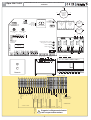 3
3
-
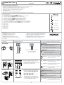 4
4
-
 5
5
-
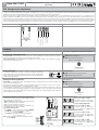 6
6
-
 7
7
-
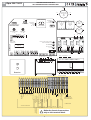 8
8
-
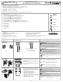 9
9
-
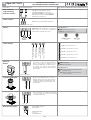 10
10
-
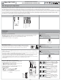 11
11
-
 12
12
-
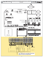 13
13
-
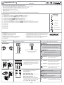 14
14
-
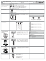 15
15
-
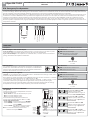 16
16
-
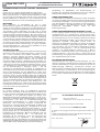 17
17
-
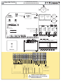 18
18
-
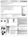 19
19
-
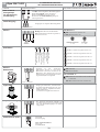 20
20
-
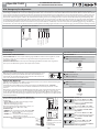 21
21
-
 22
22
-
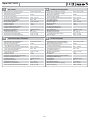 23
23
-
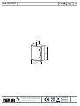 24
24


Fadini elpro-s50-T1.EFO Instructions Manual
- Tipo
- Instructions Manual
in altre lingue
- English: Fadini elpro-s50-T1.EFO
- français: Fadini elpro-s50-T1.EFO
- Deutsch: Fadini elpro-s50-T1.EFO
Documenti correlati
-
Fadini elpro-s50-T3 Instructions Manual
-
-
-
-
-
-
-
-