
1
GENERALITA'
Il modem per collegamenti a breve distanze tipo LCM 7 è un
semplice apparato che permette la trasmissione di dati asincroni
fino a 19200 bit/s. con linee a continuità galvanica a 4 fili.
Le contenute dimensioni meccaniche unite alla caratteristica di
non richiedere alimentazione da rete o batterie, consentono un
impiego generalizzato in reti locali asincrone. Sono disponibili 3
modelli di LCM 7 che, pur presentando le stesse caratteristiche
funzionali, consentono di adattarsi meccanicamente ed
elettricamente ad ogni esigenza.
LCM 7/MM (8D1013) Interfaccia modem con connettore maschio
LCM 7/MF (8D1113) Interfaccia modem con connettere femmina
LCM 7/TM (8D1213) Interfaccia terminale con connettore maschi
o
CARATTERISTICHE MECCANICHE
l Larghezza 56mm l Profondità 75mm
l Altezza 20mm l Peso 75gr
CARATTERISTICHE AMBIENTALI
l Temperatura di funzionamento da -0° a +50°
l Temperatura di immagazzinaggio da -20° a +80°
l Umidità max 92% con cond.
CARATTERISTICHE ELETTRICHE
Interfaccia dati
Velocità di esercizio: fino a 19200 bit/s.
Livello segnali: in accordo alle specifiche CCITT V24/28
e EIA RS 232-C
Linea di supporto
Tipo: 2 coppie continue e twistate
Distanze: oltre i 1500 mt. con linea a 6/10 mm di
diametro alla velocità di 9600 bit/s
NOTA: Le prestazioni (distanza/velocità) sono comunque
proporzionali alle alimentazioni fornite al modem tramite i segnali
dell'interfaccia specificati più avanti.

2
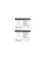
INTERFACCIA MODELLI LCM 7/MF-LCM 7/MM
Contatto Sigla
Connettore circuitoLCM 7-DTE Descrizione
2 C103 <----- Dati trasmessi (alimentazione
negativa a LCM 7)
3 C104 -----> Dati ricevuti
4 C105 <----- Richiesta di trasmissione
(alimentazione positiva a LCM 7)
5 C106 -----> Pronti a trasmettere
6 C107 -----> Modem pronto
20 C108 <----- Terminali dati pronto
(alimentazione positiva a LCM 7)
7 C102 <----> Massa segnali
8 C109 -----> Rivelatore di portante
9 - <----- Alimentazione positiva a LCM 7
10 - <----- Alimentazione negativa a LCM 7
NOTE:
l La trasmissione del modem è vincolata allo stato del C105 (stato
di lavoro=trasmissione)
l Le alimentazioni sui contatti 9 e 10 non sono indispensabili al
funzionamento del modem.
INTERFACCIA MODELLO LCM 7 T/M
Contatto Sigla
ConnettorecircuitoLCM 7-DTE Descrizione
2 C103 -----> Dati trasmessi (alimentazione
negativa a LCM 7)
3 C104 <----- Dati ricevuti (alimentazione
negativa a LCM 7)
4 C105 -----> Richiesta di trasmissione
5 C105 <----- Pronto a trasmettere
(alimentazione positiva a LCM 7)
6 C107 <----- Modem pronto (alimentazione
positiva a LCM 7)
20 C108 -----> Terminali dati pronto
7 C102 <----> Massa segnali
8 C109 <----- Rivelazione portante
(alimentazione positiva a LCM 7)
9 - <----- Alimentazione positiva a LCM 7
10 - <----- Alimentazione negativa a LCM 7
NOTE:
l La trasmissione del modem è vincolata allo stato del C109 (stato
di lavoro=trasmissione)
l Le alimentazioni sui contatti 9 e 10 non son indispensabili al
funzionamento del modem.

3
INSTALLAZIONE
a) Connettere la linea rispettando le polarità ai morsetti a vite.
b) Inserire il modem LCM 7 sull'interfaccia dell'utilizzatore da
collegare.
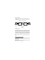
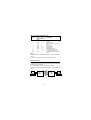
ESEMPIO DI COLLEGAMENTO
Per l'eventuale prova di un LCM 7 (loop locale) collegare i
morsetti:
TXA RXA
TXB RXB
INTRODUCTION
LCM7 operates asynchronously over full duplex 4 wire circuits at
speeds of up to 19,24 KBit/s for point to point operations. LCM7
plug directly into the back of your asyncronous terminal or modem,
occupyng a fraction of the space required for a typical standalone
unit and the LCM7 eliminates the need for bulky RS232 cable,
since the 4 wire lines attach directly to the screw terminal on each
unit.
Perfomance may vary depending on operating conditions and wire
gauge.
LCM7 is available in three models:
LCM 7MM (8D1013) with male DB25P connector for DTE
direct connection
LCM 7MF (8D1113) with female DB25S connector for DTE
direct connection
LCM 7TM (8D1213) with male DB25P connector for DCE
direct connection (interface crossed)
LCM 7
M-M
LCM 7
T-M
TXA
TXA
TXB
TXB
RXA
RXA
RXB
RXB

4
SPECIFICATION
l Power: +12/-12Vdc from DTE/DCE interface, pins2,4,20,9,10
l Size: 20mm (H) x 56mm (W) x 75mm (D)
l Weight: 75gr
l Enclosure: metallic
l Interfaces: digital RS232 (CCITT V24/28) analog twisted pairs,
costumer-owned cable
l Connectors: DB25P (male) or DB25S (female) connector;
line: screw terminals
l Data rates: up to 19,24 KBit/s.
lDistance: 1500mt with unshielded twisted pair 0,6mm (diameters)
or 24 AWG.
PIN OUT TABLE FOR LCM7 MF/LCM7MM
25Pin CCITT DTE Description
V24 LCM7-DTE
circuit
2 C103 <----- Trasmitted data (-V negative
source)
3 C104 -----> Received data
4 C105 <----- Request to send (+V positive
source)
5 C106 -----> Clear to send
6 C107 -----> Data set ready
7 C102 <----> Signal ground
8 C109 -----> Data carrier detector
9 - <----- +V auxiliary power source
10 - <----- -V auxiliary power source
20 C108 <----- Data terminal ready (+V positive
source)
NOTE:
The trasmission is controlled by the status of C105 on the interface
(pin 4).
A ON state on this pin is necessary to send data on the line.

5
PIN OUT TABLE FOR LCM7 T/M
25Pin CCITT DTE Description
V24 LCM7-DCE
circuit
2 C103 -----> Trasmitted data (-V negative
source)
3 C104 <----- Received data
4 C105 -----> Request to send (+V positive
source)
5 C106 <----- Clear to send
6 C107 <----- Data set ready
7 C102 <----> Signal ground
8 C109 <----- Data carrier detector
9 - -----> +V auxiliary power source
10 - -----> -V auxiliary power source
20 C108 -----> Data terminal ready (+V positive
source)
NOTE:
The trasmission is controlled by the status of C109 on the interface
(pin 8).
A ON state on this pin is necessary to send data on line.
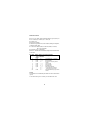
INSTALLATION
To install LCM7 simply plug the modem into the V24 DB25
terminal modem connector.
Then connect the line cable to the 4 screw terminals.
All modem are polarity sensitive cable must be wired as following
figure:
LCM 7
M-M
LCM 7
T-M
TXA
TXA
TXB
TXB
RXA
RXA
RXB
RXB

ADDENDUM al manuale operativo
LCM7 Cod. 7D0300
(rilasciato il 02/96)
ATTENZIONE
Per rendere conforme l'apparato LCM7 alla Direttiva 89/336
(compatibilità elettromagnetica), è necessario collegare il modem
direttamente all'interfaccia seriale RS 232 del Personal Computer,
oppure utilizzare un cavo con la schermatura collegata sulla parte
meccanica di entrambi i connettori RS232.
Inoltre è necessario utilizzare la copertura in plastica per i morsetti
di linea dopo aver fatto gli opportuni collegamenti
ATTENTION
In order to make the LCM7 device conform to the Directive 89/336
(electromagnetic compatibility), is necessary to connect the modem
directly to the RS232 interface serial of the Personal Computer or
user a cable with the screening connected of both the RS 232
connectors.
Additionally is necessary to use the cover for the connector line.

MODEM
LCM 7
Asynchronous non powered
short haul modem
MANUALE OPERATIVO
USER'S MANUAL
COD. 7D0300

SEDE LEGALE, DIREZIONE ed UFFICI
REGISTERED AND HEAD OFFICE
ITALY - 21010 Cardano al Campo VA
Via Alessandro Volta 39
Tel. 0331/263122 - Fax 0331/263733
Tel.0331/702611 (da Giugno 97)
Tel. +39/331/263122 - Fax +39/331/263733
new phone number starting 2 June 97: +39/331/702611
http://www.digicom.it
HOT LINE
Tel. 0331/261649 Fax 0331/730800
Tel. +39/331/261649 Fax +39/331/730800
-
 1
1
-
 2
2
-
 3
3
-
 4
4
-
 5
5
-
 6
6
-
 7
7
-
 8
8


