Avdel 07537 Manuale del proprietario
- Categoria
- Utensili elettrici
- Tipo
- Manuale del proprietario

Genesis
®
7537
Hydro-Pneumatic Power Tool
Druckluftgerät
Outil oléo-pneumatique
Attrezzo oleopneumatico
07537
07537
Instruction Manual
Manuel d’instructions
Betriebsanleitung
Manuale d’istruzione

La pagina si sta caricando...
La pagina si sta caricando...

5
Specification for 07537 Tool
Tool Dimensions
Specifications
Air Pressure Minimum - Maximum 5-7 bar (70-100 lbf/in
2
)
Free Air Volume Required @ 5.1 bar /75 lbf/in
2
2.6 litres (0.09 ft
3
)
Stroke Minimum 28.0 mm (1.10 in)
Pull Force @ 5.5 bar /80 lbf/in
2
3.89 kN (875 lbf)
Cycle time Approximately 1 second
Noise Level Less than 70 dB(A)
Weight Tool 2.3 kg (5.06 lb)
Vibration Less than 2.5 m/s
2
(8 ft/s
2
)
07537
475
18.70
338
13.30
51
2
110
120
121
150
60
2.36
98
3.85
163
6.41
140
5.51
50
1.96
07537
Part Number 07537-00200
English
La pagina si sta caricando...
La pagina si sta caricando...

8
Mechanical Cursors
Putting into Service
MECHANICAL CURSOR
PART NO.
END PLUG
PART NO.
07271-01100
07279-05843
07279-05845
07150-00402
07159-05844
07159-05846
COLOUR
PLAIN STEEL
GOLD
SILVER
HOLE DIAMETER
(mm)
2.7
2.2
3.3
For reference there are three different mechanical cursor types:
• 07271-01100 Used for Standard mandrels and 5/32” Disposable mandrels
• 07279-05843 Used for 1/8” Disposable mandrels
• 07279-05845 Used for 3/16” Disposable mandrels
The difference in the above assemblies is the internal diameter of the End Plug.
These are colour coded see below:
END PLUG
NOSE
JAWS
TOOL
BARREL
CURSOR
SPRING
LOADED END
La pagina si sta caricando...
La pagina si sta caricando...

11
Putting into Service
3
/16"
3
/32"
3
/32"
5
/32"
5
/32"
3
/16"
3
/16"
3mm
6 x 32
UNC
2.5mm
4 x 40
UNC
3
/32"
3
/32"
1
/8"
1
/4"
1
/8"
2.8mm
2.5mm
2.8mm
3mm
3.5mm
4mm
2.8mm
CHOBERT
®
AVLUG
®
GROVIT
®
CHOBERT
®
GROVIT
®
CHOBERT
®
RIVSCREW
®
BRIV
®
AVSERT
®
AVTRONIC
®
MANDREL HEAD
FERRULE
MANDREL FOLLOWER SPRING
SPRING
MANDREL
STANDARD TAPERED
ALL
ALL
ALL
ALL EXCEPT
STANDARD TAPERED,
LIMITED ACCESS
ALL EXCEPT
LIMITED ACCESS
STANDARD TAPERED,
LIMITED ACCESS
ALL
ALL
ALL
ALL
ALL
ALL
ALL
ALL
ALL
ALL
LIMITED ACCESS
5
/32"
FASTENER
SIZENAME
NOSE JAW
(SEE NOSE EQUIPMENT SECTION)
ALL
ALL
ALL
ALL
ALL
ALL
ALL
ALL
ALL EXCEPT
3rd
OVERSIZE
3rd
OVERSIZE
ALL EXCEPT
2nd
OVERSIZE
2nd
OVERSIZE
ALL
ALL
ALL
ALL
ALL
ALL
ALL
MANDREL
SIZE
MANDREL FOLLOWER SPRINGS IDENTIFICATION AND ORIENTATION
MANDREL/MANDREL FOLLOWER SPRING
AND FASTENER ASSEMBLY
LIMITED ACCESS &
LIMITED ACCESS CAM OPERATED
STANDARD
ALL
EXCEPT 3rd
OVERSIZE
6mm
ALL ALL
English
La pagina si sta caricando...
La pagina si sta caricando...

14
Nose Jaw Selection - Imperial
Nose Assemblies
The ‘REF Nº’ column cross references with the ‘REF Nº’ columns in the mandrel section. It identifies both the mandrel and mandrel
follower spring required for a particular nose jaw with a specific fastener.
# These nose jaws are suitable for placing Chobert
®
rivets with a Universal Head Form. When used on the equivalent size of Briv
®
, the
highest possible clench is achieved. Note when using Briv
®
fasteners, the maximum grip is reduced by approximately 0.015" (0.4mm).
25
26
27
27
28
29
29
30
31
32
33
34
35
37
38
39
40
41
STD. CAM OPERATED
LONG CAM OPERATED
STANDARD - FLAT
STD. CAM OPERATED - FLAT
LONG CURVED - FLAT
STANDARD - FLAT
STD. CAM OPERATED - FLAT
LONG CURVED - FLAT
STANDARD - FLAT
STANDARD - FLAT
STANDARD - FLAT
LONG - FLAT
STANDARD - FLAT
LONG - FLAT
STD. CAM OPERATED - HF
STD. CAM OPERATED - HF
STD. CAM OPERATED - HF
STD. CAM OPERATED - HF
07170-05600
07170-05700
07150-03003
07170-04500
07150-05003
07150-03004
07170-04600
07150-05004
07150-03003
07150-03004
07150-03003
07150-04003
07271-05600
07271-05900
07271-03000
07271-03000
07271-03500
07271-04000
.64
.64
.36
.36
.41
.41
.41
.41
.36
.41
.36
.41
.36
.41
.41
.41
.41
.41
1.21
2.19
1.30
1.30
2.28
1.18
1.18
2.12
1.30
1.18
1.30
2.30
1.30
2.30
1.18
1.18
1.18
1.18
.52
.52
.16
.16
.16
.20
.20
.20
.16
.20
.16
.16
.16
.16
.24
.24
.24
.25
6mm BRIV®
Al. Alloy, Steel
3/32" AVLUG®
1/8" AVLUG®
2.5mm AVTRONIC®
2.8mm AVTRONIC®
2.8mm RIVSCREW®
3.0mm RIVSCREW®
3.5mm RIVSCREW®
4.0mm RIVSCREW®
2.5mm, 4-40 UNC
AVSERT®
3.0mm, 6-32 UNC
AVSERT®
25
26
27
28
29
30
30
-
32
33
-
36
-
-
-
-
-
STANDARD - FLAT
LONG - FLAT
STANDARD - TAPERED
LONG - FLAT
-
STANDARD - TAPERED
LONG - FLAT
LONG CAM OPERATED - FLAT
-
STD. CAM OPERATED - FLAT
LTD. ACCESS CAM OPERATED
-
LTD. ACCESS CAM OPERATED
-
-
-
-
-
07170-05800
07170-05900
07150-03103
07150-04003
-
07170-03104
07150-04004
07170-05000
-
07170-04600
07271-08000
-
07271-08100
-
-
-
-
-
.64
.64
.36
.41
-
.41
.41
.41
-
.41
.41
-
.40
-
-
-
-
-
1.21
2.19
1.30
2.30
-
1.19
2.18
2.18
-
1.18
1.18
-
1.18
-
-
-
-
-
.52
.52
.16
.16
-
.20
.20
.20
-
.20
.16
-
.16
-
-
-
-
-
13
14
15
15
16
16
17
18
18
19
20
20
21
22
22
23
24
24
STANDARD - TAPERED
LIMITED ACCESS
STANDARD - FLAT
STANDARD - TAPERED
LONG - RECESSED
LONG CURVED - RECESSED
STANDARD - FLAT
LONG - FLAT
LONG CURVED - FLAT
STANDARD - FLAT
LONG - FLAT
LONG CURVED - FLAT
STANDARD - FLAT
LONG - FLAT
LONG CURVED - FLAT
STANDARD - FLAT
LONG - FLAT
LONG CURVED - FLAT
07170-03103
07274-01000
07150-03004
07170-03104
07170-03204
07170-03304
07150-03005
07150-04005
07150-05005
07150-03005
07150-04005
07150-05005
07150-03006
07150-04006
07150-05006
07150-03006
07150-04006
07150-05006
.36
.22
.41
.41
.41
.41
.48
.48
.48
.48
.48
.48
.56
.56
.56
.56
.56
.56
1.30
1.07
1.18
1.19
2.18
2.12
1.30
2.30
2.23
1.30
2.30
2.23
1.18
2.30
2.21
1.18
2.30
2.21
.15
.16
.20
.20
.30
.30
.24
.24
.24
.24
.24
.24
.33
.33
.33
.33
.33
.33
3/32" BRIV®
Brass only
1/8" BRIV®
Al. Alloy,
Brass, Steel
5/32" BRIV®
Al. Alloy,
Brass, Steel
5/32" BRIV®
St.Steel only
3/16" BRIV®
Al. Alloy,
Brass, Steel
3/16" BRIV®
St.Steel only
14
-
15
16
16
-
17
18
18
19
20
20
21
22
22
23
24
24
LTD. ACCESS CAM OPERATED
-
STANDARD - RECESSED
LONG - FLAT
LONG CURVED - FLAT
-
STANDARD - RECESSED
LONG - RECESSED
LONG CURVED - RECESSED
STANDARD - RECESSED
LONG - RECESSED
LONG CURVED - RECESSED
STANDARD - RECESSED
LONG - RECESSED
LONG CURVED - RECESSED
STANDARD - RECESSED
LONG - RECESSED
LONG CURVED - RECESSED
07177-03003
-
07170-03004
07150-04004
07150-05004
-
07170-03005
07170-03205
07170-03305
07170-03005
07170-03205
07170-03305
07170-03006
07170-03206
07170-03306
07170-03006
07170-03206
07170-03306
.20
-
.41
.41
.41
-
.48
.48
.48
.48
.48
.48
.56
.56
.56
.56
.56
.56
1.18
-
1.20
2.18
2.12
-
1.32
2.30
2.23
1.32
2.30
2.23
1.20
2.30
2.21
1.20
2.30
2.21
.16
-
.30
.20
.20
-
.41
.41
.41
.41
.41
.41
.47
.47
.47
.47
.47
.47
FASTENER
REF.
Nº
1
1
2
4
5
5
6
6
7
7
8
8
9
9
10
10
11
12
STANDARD - FLAT
STD. CAM OPERATED - FLAT
STANDARD - TAPERED
LONG - FLAT
STANDARD - FLAT
STANDARD - TAPERED
LONG - FLAT
LONG CURVED - FLAT
STANDARD - FLAT
STANDARD - TAPERED
LONG - FLAT
LONG CURVED - FLAT
STANDARD - FLAT
STANDARD - TAPERED
LONG - FLAT
LONG CURVED - FLAT
STANDARD - FLAT
LONG - FLAT
07150-03003
07170-04500
07170-03103
07150-04003
07150-03004
07170-03104
07150-04004
07150-05004
07150-03005
07150-03105
07150-04005
07150-05005
07150-03006
07150-03106
07150-04006
07150-05006
07150-03008
07150-04008
.36
.36
.36
.41
.41
.41
.41
.41
.48
.44
.48
.48
.56
.56
.56
.56
.64
.64
1.30
1.30
1.30
2.30
1.18
1.19
2.18
2.12
1.30
1.30
2.30
2.23
1.18
1.18
2.30
2.21
1.18
2.18
.16
.16
.16
.16
.20
.20
.20
.20
.24
.24
.24
.24
.33
.33
.33
.33
.39
.39
PART Nº
NOSE JAW
TYPE AND
END FORM
DIMENSIONS
'D' 'E''B'
3/32" CHOBERT®
& GROVIT®
1/8" CHOBERT®
& GROVIT®
5/32" CHOBERT®
& GROVIT®
3/16" CHOBERT®
& GROVIT®
1/4" CHOBERT®
REF.
Nº
1
1
3
4
5
5
6
6
7
7
8
8
9
9
10
10
11
12
PART Nº
NOSE JAW
TYPE AND
END FORM
DIMENSIONS
'D' 'E''B'
# STANDARD - UNIVERSAL
LTD. ACCESS CAM OPERATED
LIMITED ACCESS
LONG CURVED - FLAT
# STANDARD - UNIVERSAL
STD. CAM OPERATED - FLAT
# LONG - UNIVERSAL
LONG CAM OPERATED - FLAT
# STANDARD - UNIVERSAL
STD. CAM OPERATED - FLAT
# LONG - UNIVERSAL
LONG CAM OPERATED - FLAT
# STANDARD - UNIVERSAL
STD. CAM OPERATED - FLAT
# LONG - UNIVERSAL
LONG CAM OPERATED - FLAT
STD. CAM OPERATED - FLAT
LONG CAM OPERATED - FLAT
07150-03203
07177-03003
07274-01000
07150-05003
07150-03204
07170-04600
07150-04204
07170-05000
07150-03205
07170-04700
07150-04205
07170-05100
07150-03206
07170-04800
07150-04206
07170-05200
07170-04900
07170-05300
.36
.20
.22
.41
.41
.41
.41
.41
.48
.48
.48
.48
.56
.56
.56
.56
.64
.64
1.33
1.18
1.07
2.28
1.22
1.18
2.22
2.18
1.35
1.30
2.35
2.30
1.24
1.18
2.39
2.30
1.18
2.18
.24
.16
.16
.16
.32
.20
.30
.20
.41
.24
.42
.24
.47
.33
.48
.33
.39
.39

15
Nose Jaw Selection - Metric
Nose Assemblies
STD. CAM OPERATED
LONG CAM OPERATED
STANDARD - FLAT
STD. CAM OPERATED - FLAT
LONG CURVED - FLAT
STANDARD - FLAT
STD. CAM OPERATED - FLAT
LONG CURVED - FLAT
STANDARD - FLAT
STANDARD - FLAT
STANDARD - FLAT
LONG - FLAT
STANDARD - FLAT
LONG - FLAT
STD. CAM OPERATED - HF
STD. CAM OPERATED - HF
STD. CAM OPERATED - HF
STD. CAM OPERATED - HF
07170-05600
07170-05700
07150-03003
07170-04500
07150-05003
07150-03004
07170-04600
07150-05004
07150-03003
07150-03004
07150-03003
07150-04003
07271-05600
07271-05900
07271-03000
07271-03000
07271-03500
07271-04000
16.33
16.33
9.14
9.14
10.41
10.41
10.41
10.41
9.14
10.41
9.14
10.41
9.14
10.41
10.41
10.41
10.41
10.41
30.65
55.65
33.02
33.02
57.91
29.97
29.97
53.85
33.02
29.97
33.02
58.42
33.02
58.42
29.97
29.97
29.97
29.97
13.14
13.14
4.06
4.06
4.06
5.08
5.08
5.08
4.06
5.08
4.06
4.06
4.06
4.06
6.10
6.10
6.10
6.35
6mm BRIV®
Al. Alloy, Steel
3/32" AVLUG®
1/8" AVLUG®
2.5mm AVTRONIC®
2.8mm AVTRONIC®
2.8mm RIVSCREW®
3.0mm RIVSCREW®
3.5mm RIVSCREW®
4.0mm RIVSCREW®
2.5mm, 4-40 UNC
AVSERT®
3.0mm, 6-32 UNC
AVSERT®
25
26
27
28
-
29
30
30
-
32
33
-
36
-
-
-
-
-
STANDARD - FLAT
LONG - FLAT
STANDARD - TAPERED
LONG - FLAT
-
STANDARD - TAPERED
LONG - FLAT
LONG CAM OPERATED - FLAT
-
STD. CAM OPERATED - FLAT
LTD. ACCESS CAM OPERATED
-
LTD. ACCESS CAM OPERATED
-
-
-
-
-
07170-05800
07170-05900
07150-03103
07150-04003
-
07170-03104
07150-04004
07170-05000
-
07170-04600
07271-08000
-
07271-08100
-
-
-
-
-
16.33
16.33
9.14
10.41
-
10.41
10.41
10.41
-
10.41
10.41
-
10.16
-
-
-
-
-
30.65
55.65
33.02
58.42
-
30.23
55.37
55.37
-
29.97
29.97
-
29.97
-
-
-
-
-
13.14
13.14
4.06
4.06
-
5.08
5.08
5.08
-
5.08
4.06
-
4.06
-
-
-
-
-
13
14
15
15
16
16
17
18
18
19
20
20
21
22
22
23
24
24
STANDARD - TAPERED
LIMITED ACCESS
STANDARD - FLAT
STANDARD - TAPERED
LONG - RECESSED
LONG CURVED - RECESSED
STANDARD - FLAT
LONG - FLAT
LONG CURVED - FLAT
STANDARD - FLAT
LONG - FLAT
LONG CURVED - FLAT
STANDARD - FLAT
LONG - FLAT
LONG CURVED - FLAT
STANDARD - FLAT
LONG - FLAT
LONG CURVED - FLAT
07170-03103
07274-01000
07150-03004
07170-03104
07170-03204
07170-03304
07150-03005
07150-04005
07150-05005
07150-03005
07150-04005
07150-05005
07150-03006
07150-04006
07150-05006
07150-03006
07150-04006
07150-05006
9.14
5.59
10.41
10.41
10.41
10.41
12.19
12.19
12.19
12.19
12.19
12.19
14.22
14.22
14.22
14.22
14.22
14.22
33.02
27.18
29.97
30.23
55.37
53.85
33.02
58.42
56.64
33.02
58.42
56.64
29.97
58.42
56.13
29.97
58.42
56.13
3.81
4.06
5.08
5.08
7.62
7.62
6.10
6.10
6.10
6.10
6.10
6.10
8.38
8.38
8.38
8.38
8.38
8.38
3/32" BRIV®
Brass only
1/8" BRIV®
Al. Alloy,
Brass, Steel
5/32" BRIV®
Al. Alloy,
Brass, Steel
5/32" BRIV®
St.Steel only
3/16" BRIV®
Al. Alloy,
Brass, Steel
3/16" BRIV®
St.Steel only
14
-
15
16
16
-
17
18
18
19
20
20
21
22
22
23
24
24
LTD. ACCESS CAM OPERATED
-
STANDARD - RECESSED
LONG - FLAT
LONG CURVED - FLAT
-
STANDARD - RECESSED
LONG - RECESSED
LONG CURVED - RECESSED
STANDARD - RECESSED
LONG - RECESSED
LONG CURVED - RECESSED
STANDARD - RECESSED
LONG - RECESSED
LONG CURVED - RECESSED
STANDARD - RECESSED
LONG - RECESSED
LONG CURVED - RECESSED
07177-03003
-
07170-03004
07150-04004
07150-05004
-
07170-03005
07170-03205
07170-03305
07170-03005
07170-03205
07170-03305
07170-03006
07170-03206
07170-03306
07170-03006
07170-03206
07170-03306
5.08
-
10.41
10.41
10.41
-
12.19
12.19
12.19
12.19
12.19
12.19
14.22
14.22
14.22
14.22
14.22
14.22
29.97
-
30.48
55.37
53.85
-
33.53
58.42
56.64
33.53
58.42
56.64
30.48
58.42
56.13
30.48
58.42
56.13
4.06
-
7.62
5.08
5.08
-
10.41
10.41
10.41
10.41
10.41
10.41
11.94
11.94
11.94
11.94
11.94
11.94
FASTENER
REF.
Nº
1
1
2
4
5
5
6
6
7
7
8
8
9
9
10
10
11
12
STANDARD - FLAT
STD. CAM OPERATED - FLAT
STANDARD - TAPERED
LONG - FLAT
STANDARD - FLAT
STANDARD - TAPERED
LONG - FLAT
LONG CURVED - FLAT
STANDARD - FLAT
STANDARD - TAPERED
LONG - FLAT
LONG CURVED - FLAT
STANDARD - FLAT
STANDARD - TAPERED
LONG - FLAT
LONG CURVED - FLAT
STANDARD - FLAT
LONG - FLAT
07150-03003
07170-04500
07170-03103
07150-04003
07150-03004
07170-03104
07150-04004
07150-05004
07150-03005
07150-03105
07150-04005
07150-05005
07150-03006
07150-03106
07150-04006
07150-05006
07150-03008
07150-04008
9.14
9.14
9.14
10.41
10.41
10.41
10.41
10.41
12.19
11.18
12.19
12.19
14.22
14.22
14.22
14.22
16.26
16.26
33.02
33.02
33.02
58.42
29.97
30.23
55.37
53.85
33.02
33.02
58.42
56.64
29.97
29.97
58.42
56.13
29.97
55.37
4.06
4.06
4.06
4.06
5.08
5.08
5.08
5.08
6.10
6.10
6.10
6.10
8.38
8.38
8.38
8.38
9.91
9.91
PART Nº
NOSE JAW
TYPE AND
END FORM
DIMENSIONS
'D' 'E''B'
3/32" CHOBERT®
& GROVIT®
1/8" CHOBERT®
& GROVIT®
5/32" CHOBERT®
& GROVIT®
3/16" CHOBERT®
& GROVIT®
1/4" CHOBERT®
REF.
Nº
1
1
3
4
5
5
6
6
7
7
8
8
9
9
10
10
11
12
PART Nº
NOSE JAW
TYPE AND
END FORM
DIMENSIONS
'D' 'E''B'
# STANDARD - UNIVERSAL
LTD. ACCESS CAM OPERATED
LIMITED ACCESS
LONG CURVED - FLAT
# STANDARD - UNIVERSAL
STD. CAM OPERATED - FLAT
# LONG - UNIVERSAL
LONG CAM OPERATED - FLAT
# STANDARD - UNIVERSAL
STD. CAM OPERATED - FLAT
# LONG - UNIVERSAL
LONG CAM OPERATED - FLAT
# STANDARD - UNIVERSAL
STD. CAM OPERATED - FLAT
# LONG - UNIVERSAL
LONG CAM OPERATED - FLAT
STD. CAM OPERATED - FLAT
LONG CAM OPERATED - FLAT
07150-03203
07177-03003
07274-01000
07150-05003
07150-03204
07170-04600
07150-04204
07170-05000
07150-03205
07170-04700
07150-04205
07170-05100
07150-03206
07170-04800
07150-04206
07170-05200
07170-04900
07170-05300
9.14
5.08
5.59
10.41
10.41
10.41
10.41
10.41
12.19
12.19
12.19
12.19
14.22
14.22
14.22
14.22
16.26
16.26
33.78
29.97
27.18
57.91
30.99
29.97
56.39
55.37
34.29
33.02
59.69
58.42
31.50
29.97
60.71
58.42
29.97
55.37
6.10
4.06
4.06
4.06
8.13
5.08
7.62
5.08
10.41
6.10
10.67
6.10
11.94
8.38
12.19
8.38
9.91
9.91
25
26
27
27
28
29
29
30
31
32
33
34
35
37
38
39
40
41
# These nose jaws are suitable for placing Chobert
®
rivets with a Universal Head Form. When used on the equivalent size of Briv
®
, the
highest possible clench is achieved. Note that when using Briv
®
fasteners, the maximum grip is reduced by approximately 0.015" (0.4mm).
English

16
Mandrels and Mandrel Follower Springs
Chobert
®
and Grovit
®
- Imperial
Nose Assemblies
Mandrels and mandrel follower springs, illustrated on page 11 need to be selected to suit the fastener type and size as well as the size
of the hole in the application. Use of the wrong mandrel could increase the risk of breakage and the wear of the mandrel head.
Feeding problems could occur if the wrong mandrel follower spring is used.
For mandrel or mandrel follower spring selection, follow instructions on page 18.
IMPORTANT
READ THE SAFETY INSTRUCTIONS page 4 carefully.
While a small amount of wear and marking will naturally occur through normal and correct use of mandrels, they
must be regularly examined for excessive wear and marking, with particular attention to the head diameter, the
tail jaw gripping area of the shank or heavy pitting of the shank and any mandrel distortion. Mandrels which fail
during use could forcibly exit the tool. It is the customer’s responsibility to ensure that mandrels are replaced
before any excessive levels of wear and always before the maximum recommended number of placings.
Contact your Avdel UK Limited representative who will let you know what that figure is by measuring the broach
load of your application with our calibrated measuring tool. These tools can also be purchased under part
number 07900-09080, supplied with all necessary information for testing.
FA
S
TENE
R
REF.
N
º
P
MAX.
S
PRIN
G
PART N
º
S
TANDARD MANDREL -
G
REE
N
H
O
L
E
S
IZ
E
1
S
T
O
VER
S
IZE MANDREL - YELL
OW
3
/
32" CHOBER
T
®
&
G
R
O
VI
T
®
1
/
8" CHOBER
T
®
&
G
R
O
VI
T
®
5
/
32" CHOBER
T
®
&
G
R
O
VI
T
®
3
/
16" CHOBER
T
®
&
G
R
O
VI
T
®
1
/
4" CHOBER
T
®
.1
66
-
.1
66
-
.1
66
-
.1
66
.21
6
.21
6
.244
-
.244
-
.247
-
.247
-
.2
68
P
MAX.
.
0
7
1
-
.
0
7
1
-
.
0
7
1
-
.
0
7
1
.
090
.
090
-
.1
00
-
.1
02
-
.1
02
-
.11
0
PART N
º
0
71
50
-
06003
-
0
71
50
-
06003
-
0
71
50
-
06003
-
0
71
50
-
0
7
003
0
71
50
-
0600
4
0
71
50
-
0
7
00
4
0
71
50
-
06005
-
0
71
50
-
0
7
005
-
0
71
50
-
06006
-
0
71
50
-
0
7
006
-
0
71
50
-
06008
0
71
50
-
0
7
008
PART N
º
0
71
50
-
08003
-
0
71
50
-
08003
-
0
71
50
-
08003
-
0
71
50
-
09003
0
71
50
-
08004
0
71
50
-
09004
-
0
71
50
-
09005
-
0
71
50
-
08006
-
0
71
50
-
09006
-
0
71
50
-
08008
A
S
RE
C.
-
A
S
RE
C.
-
A
S
RE
C.
-
A
S
RE
C.
A
S
RE
C.
A
S
RE
C.
A
S
RE
C.
-
A
S
RE
C.
-
A
S
RE
C.
-
A
S
RE
C.
-
A
S
RE
C.
A
S
RE
C.
HEAD
Ø
.
0
72
5
-
.
0
72
5
-
.
0
72
5
-
.
0
72
5
.
088
.
088
.1
07
-
.1
07
-
.1
32
-
.1
32
-
.1
84
.1
84
MAX.
H
O
L
E
S
IZ
E
.174
-
.174
-
.174
-
-
.2
37
.2
37
.2
84
-
.2
84
-
.
3
2
0
-
.
3
2
0
-
.
330
.
330
MAX.
-
-
.
0
7
8
-
.
0
7
8
.
098
.
098
-
.11
6
-
.1
30
-
.1
30
-
.1
34
MANDREL
PART N
º
0
71
50
-
06303
-
0
71
50
-
06303
-
0
71
50
-
06303
-
-
0
71
50
-
06
1
04
0
71
50
-
0
71
04
0
71
50
-
06
1
05
-
0
71
50
-
0
71
05
-
0
71
50
-
06
1
06
-
0
71
50
-
0
71
06
-
0
71
50
-
06
1
08
0
71
50
-
0
71
08
PART N
º
-
0
71
50
-
08
1
03
-
0
71
50
-
08
1
03
-
0
71
50
-
08
1
03
0
71
50
-
09
1
03
0
71
50
-
08
1
04
0
71
50
-
09
1
04
0
71
50
-
08
1
05
-
0
71
50
-
09
1
05
-
0
71
50
-
08
1
06
-
0
71
50
-
09
1
06
-
0
71
50
-
08
1
08
0
71
50
-
09
1
08
+.
00
1
5
+.
00
1
5
+.
0035
+.
00
1
5
+.
0035
+.
004
+.
004
-
+.
008
-
+.
0
1
4
-
+.
0
1
4
-
+.
0
1
2
HEAD
Ø
.
0
7
4
.
0
7
4
.
0
7
6
.
0
7
4
.
0
7
6
.
092
.
092
.11
5
-
.11
5
-
.14
6
-
.14
6
-
.1
96
.1
96
0
71
50
-
06803
0
71
50
-
06803
0
717
0
-
068
7
3
0
717
0
-
068
7
3
0
717
0
-
06903
0
71
50
-
0
7
803
0
71
50
-
06804
0
71
50
-
0
7
804
-
0
717
0
-
0
7
8
7
5
-
0
717
0
-
068
7
6
-
0
717
0
-
0
7
8
7
6
-
0
71
50
-
06808
FA
S
TENE
R
N
º
P
S
PRIN
G
PART
N
º
H
O
L
E
SIZ
E
3
/
32" CHOBER
T
®
&
G
R
O
VI
T
®
1
/
8" CHOBER
T
®
&
G
R
O
VI
T
®
5
/
32" CHOBER
T
®
&
G
R
O
VI
T
®
3
/
16" CHOBER
T
®
&
G
R
O
VI
T
®
1
/
4" CHOBER
T
®
.1
85
-
.1
85
-
.1
85
-
.1
85
.2
68
.
3
2
0
-
.
3
2
0
-
-
.
3
7
2
-
.
3
7
2
-
-
P
-
-
-
-
-
-
-
.1
30
-
.1
30
-
-
.1
50
-
.1
50
-
-
MANDREL
0
71
50
-
06
1
03
-
0
71
50
-
06
1
03
-
0
71
50
-
06
1
03
-
0
71
50
-
0
71
03
0
71
50
-
06
2
0
4
0
71
50
-
0
72
0
4
0
71
50
-
06
2
05
-
0
71
50
-
0
72
05
-
-
0
71
50
-
06
2
06
-
0
71
50
-
0
72
06
-
-
PART N
º
-
-
-
-
-
-
-
0
71
50
-
08
2
05
-
0
71
50
-
09
2
05
-
-
0
71
50
-
08
2
06
-
0
71
50
-
09
2
06
-
-
+.
0035
-
+.
0035
-
+.
0035
-
+.
0035
+.
0
1
0
+.
0
1
0
+.
0
1
5
-
+.
0
1
5
-
-
+.
0
2
4
-
+.
0
2
4
-
-
HEAD
Ø
.
0
7
6
-
.
0
7
6
-
.
0
7
6
-
.
0
7
6
.
098
.
098
.122
-
.122
-
-
.1
56
-
.1
56
-
-
P
H
O
L
E
SIZ
E
-
-
-
-
-
-
-
.2
88
.2
88
-
.
3
7
2
-
.
3
7
2
-
-
-
-
-
-
P
-
-
-
-
-
-
-
-
.1
50
-
-
-
-
-
-
-
MANDREL
PART N
º
-
-
-
-
-
-
-
0
71
50
-
06304
0
71
50
-
0
7
304
-
0
71
50
-
06305
-
0
71
50
-
0
7
305
-
-
-
-
-
-
PART N
º
-
-
-
-
-
-
-
0
71
50
-
08304
0
71
50
-
09304
-
0
71
50
-
08305
-
0
71
50
-
09305
-
-
-
-
-
-
-
-
-
-
-
-
-
-
+.
0
2
5
-
+.
0
2
5
-
-
-
-
-
-
HEAD
Ø
-
-
-
-
-
-
-
.1
02
.1
02
-
.1
32
-
.1
32
-
-
-
-
-
-
0
71
50
-
06803
-
0
717
0
-
068
7
3
-
0
717
0
-
06903
-
0
71
50
-
0
7
803
0
717
0
-
068
7
5
0
71
50
-
06805
0
717
0
-
0
7
8
7
5
0
71
50
-
0
7
805
-
0
71
50
-
06806
-
0
71
50
-
0
7
806
-
-
1
1
2
2
3
3
4
5
6
7
7
8
8
9
9
1
0
1
0
11
12
1
1
2
2
3
3
4
5
6
7
7
8
8
9
9
1
0
1
0
1
1
1
2
# S/R: Short Reach Mandrel. See page 18-19 for explanation.

17
Chobert
®
and Grovit
®
- Metric
Nose Assemblies
Tables below left and right and over the next four pages list part numbers of all mandrels and mandrel follower springs available per
fastener or group of fasteners, i.e. for Chobert
®
and Grovit
®
on these pages.
While fastener sizes are always shown in their specified units, each table has been produced twice to offer dimensions in imperial units
on the left-hand page then in metric units on the right-hand page. These 'Mandrel Selection' tables cross-reference with the 'Nose Jaw
Selection' tables on pages 14-15 through the ‘Ref. Nº’ column.
It is the diameter of the head at the end of a mandrel which when pulled through controls the expansion of the fastener body.
While there are different head shapes to suit different types of fasteners (see illustration on page 19), progressive head sizes are
needed to reflect manufacturing tolerances on the diameter of the hole in your application so that the fastener always expands
sufficiently to fill the hole.
Too large a mandrel head would overstress the mandrel and mandrels which fail during use could forcibly exit the tool.
Selection tables are arranged into four 'mandrel size' sections, ranging from 'standard’ to '3rd oversize', each being colour coded as
per the end of the mandrel heads themselves.
FA
S
TENE
R
1
1
2
2
3
3
4
5
6
7
7
8
8
9
9
1
0
1
0
11
12
P
MAX.
S
PRIN
G
PART N
º
S
TANDARD MANDREL -
G
REEN
H
O
L
E
S
IZ
E
1
S
T
O
VER
S
IZE MANDREL - YELL
OW
3
/
32" CHOBER
T
®
&
G
R
O
VI
T
®
1
/
8" CHOBER
T
®
&
G
R
O
VI
T
®
5
/
32" CHOBER
T
®
&
G
R
O
VI
T
®
3
/
16" CHOBER
T
®
&
G
R
O
VI
T
®
1
/
4" CHOBER
T
®
4.22
-
4.22
-
4.22
-
4.22
5
.4
9
5
.4
9
6
.2
0
-
6
.2
0
-
6
.2
7
-
6
.2
7
-
6
.
81
P
MAX.
1.
80
-
1.
80
-
1.
80
-
1.
80
2.2
9
2.2
9
-
2.
54
-
2.
59
-
2.
59
-
2.7
9
PART N
º
0
71
50
-
06003
-
0
71
50
-
06003
-
0
71
50
-
06003
-
0
71
50
-
0
7
003
0
71
50
-
06004
0
71
50
-
0
7
004
0
71
50
-
06005
-
0
71
50
-
0
7
005
-
0
71
50
-
06006
-
0
71
50
-
0
7
006
-
0
71
50
-
06008
0
71
50
-
0
7
008
PART N
º
0
71
50
-
08003
-
0
71
50
-
08003
-
0
71
50
-
08003
-
0
71
50
-
09003
0
71
50
-
08004
0
71
50
-
09004
-
0
71
50
-
09005
-
0
71
50
-
08006
-
0
71
50
-
09006
-
0
71
50
-
08008
A
S
RE
C.
-
A
S
RE
C.
-
A
S
RE
C.
-
A
S
RE
C.
A
S
RE
C.
A
S
RE
C.
A
S
RE
C.
-
A
S
RE
C.
-
A
S
RE
C.
-
A
S
RE
C.
-
A
S
RE
C.
A
S
RE
C.
HEAD
Ø
1.
84
-
1.
84
-
1.
84
-
1.
84
2.24
2.24
2.72
-
2.72
-
3
.
35
-
3
.
35
-
4.
67
4.
67
MAX.
H
O
L
E
S
IZ
E
4.42
-
4.42
-
4.42
-
-
6
.
02
6
.
02
7.21
-
7.21
-
8
.1
3
-
8
.1
3
-
8
.
38
8
.
38
P
MAX.
-
-
1.
98
-
1.
98
2.4
9
2.4
9
-
2.
95
-
3
.
30
-
3
.
30
-
3
.4
0
MANDREL
PART N
º
0
71
50
-
06303
-
0
71
50
-
06303
-
0
71
50
-
06303
-
-
0
71
50
-
06
1
04
0
71
50
-
0
71
04
0
71
50
-
06
1
05
-
0
71
50
-
0
71
05
-
0
71
50
-
06
1
06
-
0
71
50
-
0
71
06
-
0
71
50
-
06
1
08
0
71
50
-
0
71
08
PART N
º
-
0
71
50
-
08
1
03
-
0
71
50
-
08
1
03
-
0
71
50
-
08
1
03
0
71
50
-
09
1
03
0
71
50
-
08
1
04
0
71
50
-
09
1
04
0
71
50
-
08
1
05
-
0
71
50
-
09
1
05
-
0
71
50
-
08
1
06
-
0
71
50
-
09
1
06
-
0
71
50
-
08
1
08
0
71
50
-
09
1
08
+.
04
+.
04
+.
09
+.
04
+.
09
+.1
0
+.1
0
-
+.2
0
-
+.
35
-
+.
35
-
+.
30
HEAD
Ø
1.
88
1.
93
1.
88
1.
93
1.
88
1.
93
1.
93
2.
34
2.
34
2.
92
-
2.
92
-
3
.7
1
-
3
.7
1
-
4.
98
4.
98
0
71
50
-
06803
0
71
50
-
06803
0
717
0
-
068
7
3
0
717
0
-
068
7
3
0
717
0
-
06903
0
71
50
-
0
7
803
0
71
50
-
06804
0
71
50
-
0
7
804
-
0
717
0
-
0
7
8
7
5
-
0
717
0
-
068
7
6
-
0
717
0
-
0
7
8
7
6
-
0
71
50
-
06808
FA
S
TENE
R
1
1
2
2
3
3
4
5
6
7
7
8
8
9
9
1
0
1
0
11
12
P
S
PRIN
G
PART
N
º
H
O
L
E
SIZ
E
3
/
32" CHOBER
T
®
&
G
R
O
VI
T
®
1
/
8" CHOBER
T
®
&
G
R
O
VI
T
®
5
/
32" CHOBER
T
®
&
G
R
O
VI
T
®
3
/
16" CHOBER
T
®
&
G
R
O
VI
T
®
1
/
4" CHOBER
T
®
4.7
0
-
4.7
0
-
4.7
0
-
4.7
0
6
.
81
8
.1
3
-
8
.1
3
-
-
9
.4
5
-
9
.4
5
-
-
P
MAX
.
-
-
-
-
-
-
-
2.7
9
2.7
9
3
.
30
-
3
.
30
-
-
3
.
81
-
3
.
81
-
-
MANDREL
PART
N
0
71
50
-
06
1
03
-
0
71
50
-
06
1
03
-
0
71
50
-
06
1
03
-
0
71
50
-
0
71
03
0
71
50
-
06
2
04
0
71
50
-
0
72
04
0
71
50
-
06
2
05
-
0
71
50
-
0
72
05
-
-
0
71
50
-
06
2
06
-
0
71
50
-
0
72
06
-
-
PART
N
º
-
-
-
-
-
-
-
0
71
50
-
08
2
05
-
0
71
50
-
09
2
05
-
-
0
71
50
-
08
2
06
-
0
71
50
-
09
2
06
-
-
+.
09
-
+.
09
-
+.
09
-
+.
09
+.2
5
+.2
5
+.
38
-
+.
38
-
-
+.
60
-
+.
60
-
-
HEAD
Ø
1.
93
-
1.
93
-
1.
93
-
1.
93
2.4
9
2.4
9
3
.1
0
-
3
.1
0
-
-
3
.
96
-
3
.
96
-
-
P
H
O
L
E
SIZ
E
-
-
-
-
-
-
-
7.
3
2
7.
3
2
-
9
.4
5
-
9
.4
5
-
-
-
-
-
-
P
-
-
-
-
-
-
-
3
.
00
3
.
00
-
3
.
81
-
3
.
81
-
-
-
-
-
-
MANDREL
PART
N
º
-
-
-
-
-
-
-
0
71
50
-
06304
0
71
50
-
0
7
304
-
0
71
50
-
06305
-
0
71
50
-
0
7
305
-
-
-
-
-
-
PART
N
º
-
-
-
-
-
-
-
0
71
50
-
08304
0
71
50
-
09304
-
0
71
50
-
08305
-
0
71
50
-
09305
-
-
-
-
-
-
-
-
-
-
-
-
-
+.
35
+.
35
-
+.
63
-
+.
63
-
-
-
-
-
-
HEAD
Ø
-
-
-
-
-
-
-
2.
59
2.
59
-
3
.
35
-
3
.
35
-
-
-
-
-
-
0
71
50
-
06803
-
0
717
0
-
068
7
3
-
0
717
0
-
06903
-
0
71
50
-
0
7
803
0
71
50
-
0680
4
0
71
50
-
0
7
80
4
0
717
0
-
068
7
5
0
71
50
-
06805
0
717
0
-
0
7
8
7
5
0
71
50
-
0
7
805
-
0
71
50
-
06806
-
0
71
50
-
0
7
806
-
-
REF.
N
º
N
º
# S/R: Short Reach Mandrel. See page 18-19 for explanation.
English

18
Briv
®
- Imperial
Nose Assemblies
For mandrel or mandrel follower spring selection, follow instructions above.
To find the correct part number of a mandrel for a particular application, read the instructions below after you have gathered the following
information as per example alongside. Answers for the example are shown in
grey italic.
FASTENER NAME
example Chobert
®
FASTENER SIZE
1
/
8
”
DATASHEET
Series 1125
APPLICATION HOLE SIZE
0.1335”
CLEARANCE BEHIND APPLICATION
Infinite
‘REF.Nº’ FROM NOSE JAW SELECTION TABLE
5 (standard flat)
• Subtract the minimum hole size recommended (AS REC.) in the fastener datasheet from the actual application hole size.
-example:
0.005.
• Turn to the page with the ‘Mandrel Selection’ table for your fastener, selecting either the imperial or the metric dimensions table
(pages 16-20).
-example: page 16.
• Staring with the ‘Standard Mandrel - Green’ section, find your fastener size in the left-hand column.
-example
1
/
8
” Chobert
®
& Grovit
®
.
• If you selected a nose jaw which place you fastener, you should now be able to find a line within your fastener section with the same ‘Ref
No.’ as that from the ‘Nose Jaw Selection’ table.
-example: 5.
This is your line ‘Ref. No.’ in which you will find both your mandrel and
mandrel follower spring part number. This line continues into the second half of the table for the ‘2nd’ and ‘3rd’ oversize mandrels.
• Scan along the line to the ‘hole size’ columns and select which ever is the nearest or equal to the figure calculated in step one. You may
now read the mandrel part number next to the ‘hole size’.
-example: 07150-06104
• For Chobert
®
and Grovit
®
only, most mandrels are also available in a ‘short reach’ version (see illustration on page 19). Short reach
mandrels are used to minimise the possibility of the mandrel head contacting an obstruction. This would result in the underside of the
fastener head not seating properly on the application surface, causing a lack on clench in the joint.
• Whichever size mandrel you settle on, you will also need to check the ‘P’ figure against that mandrel is adequate. ‘P’ is the clearance
required for the mandrel head at the back of the application IN ADDITION to the length of the fastener protruding through the application,
as shown in the illustration on page 19.
• You may now read the corresponding mandrel follower spring part number in the right-hand column of the table.
-example: 07150-
06804.
In all cases, satisfactory clenching of the joint should be assessed particularly if the size of the hole in your application is very close to the
next oversize hole condition, when it will be safe to select the greater size of mandrel to obtain a higher clench. REMEMBER that this will
increase the broach load and reduce the mandrel life.
FASTENER
13
14
15
16
17
18
19
20
21
22
23
24
25
26
P
MAX.
SPRING
PART Nº
STANDARD MANDREL - GREEN
HOLE
SIZE
1ST OVERSIZE MANDREL - YELLOW
3/32" BRIV®
Brass only
1/8" BRIV®
Al. Alloy,
Brass, Steel
5/32" BRIV®
Al. Alloy,
Brass, Steel
5/32" BRIV®
St.Steel only
3/16" BRIV®
Al. Alloy,
Brass, Steel
3/16" BRIV®
St.Steel only
6mm BRIV®
Al. Alloy, Steel
.119
.119
.120
.120
.136
.136
.126
.126
.157
.157
.150
.150
.165
.165
MANDREL
PART Nº
07150-06013
07150-06013
07271-06414
07271-07414
07150-06015
07150-07015
07170-06805
07170-07805
07150-06016
07150-07016
07170-06806
07170-07806
07150-06018
07150-07018
AS REC.
AS REC.
AS REC.
AS REC.
AS REC.
AS REC.
AS REC.
AS REC.
AS REC.
AS REC.
AS REC.
AS REC.
AS REC
AS REC
HEAD
Ø
.072
.072
.092
.092
.110
.110
.120
.120
.141
.141
.153
.153
.179
.179
P
MAX.
HOLE
SIZE
.123
.123
.126
.126
.142
.142
.132
.132
.164
.164
.156
.156
.171
.171
MANDREL
PART Nº
07150-06113
07150-06113
07271-06514
07271-07514
07150-06115
07150-07115
07170-06825
07170-07825
07150-06116
07150-07116
07170-06826
07170-07826
07150-06118
07150-07118
+.004
+.004
+.005
+.005
+.005
+.005
+.005
+.005
+.005
+.005
+.005
+.005
+.005
+.005
HEAD
Ø
.076
.076
.097
.097
.115
.115
.125
.125
.146
.146
.158
.158
.184
.184
07170-06873
07170-06903
07150-06814
07150-07814
07170-06875
07170-07875
07170-06875
07170-07875
07170-06876
07170-07876
07170-06876
07170-07876
07150-06846
07150-07846
FASTENER
13
14
15
16
17
18
19
20
21
22
23
24
25
26
P
MAX.
SPRING
PART Nº
2ND OVERSIZE MANDREL - BLUE
HOLE
SIZE
3RD OVERSIZE MANDREL - RED
3/32" BRIV®
Brass only
1/8" BRIV®
Al. Alloy,
Brass, Steel
5/32" BRIV®
Al. Alloy,
Brass, Steel
5/32" BRIV®
St.Steel only
3/16" BRIV®
Al. Alloy,
Brass, Steel
3/16" BRIV®
St.Steel only
6mm BRIV®
Al. Alloy, Steel
.126
.126
.133
.133
.149
.149
-
-
.170
.170
-
-
.177
.177
MANDREL
PART Nº
07150-06213
07150-06213
07271-06614
07271-07614
07150-06215
07150-07215
-
-
07150-06216
07150-07216
-
-
07150-06218
07150-07218
+.008
+.008
+.010
+.010
+.010
+.010
-
-
+.010
+.010
-
-
+.010
+.010
HEAD
Ø
.079
.079
.102
.102
.120
.120
-
-
.151
.151
-
-
.189
.189
P
MAX.
HOLE
SIZE
-
-
-
-
-
-
-
-
.173
.173
-
-
-
-
MANDREL
PART Nº
-
-
-
-
-
-
-
-
07150-06316
07150-07316
-
-
-
-
-
-
-
-
-
-
-
-
+.012
+.012
-
-
-
-
HEAD
Ø
-
-
-
-
-
-
-
-
.153
.153
-
-
-
-
07170-06873
07170-06903
07150-06814
07150-07814
07170-06875
07170-07875
-
-
07170-06876
07170-07876
-
-
07150-06846
01750-07846
REF.
Nº
REF.
Nº

19
Mandrel Head Types and ‘P’ Length
Briv
®
- Metric
Nose Assemblies
Mandrels for stainless steel Briv
®
are easily identifiable by a ‘V’ cut in the end of the mandrel heads.
When using curved nose jaws, mandrels have to be bent by hand to match the curvature of the nose jaw, thus ensuring good feed of
fasteners.
CHOBERT®, GROVIT®,
AVSERT®, AVTRONIC®
RIVSCREW®
SHORT REACH
(CHOBERT® &
GROVIT® ONLY)
BRIV®
P
P
BRIV®
(STAINLESS STEEL)
AVLUG®
P P
P
P
FASTENER
13
14
15
16
17
18
19
20
21
22
23
24
25
26
P
MAX.
SPRING
PART Nº
STANDARD MANDREL - GREEN
HOLE
SIZE
1ST OVERSIZE MANDREL - YELLOW
2.4mm BRIV®
Brass only
3.2mm BRIV®
Al. Alloy,
Brass, Steel
4.0mm BRIV®
Al. Alloy,
Brass, Steel
4.0mm BRIV®
St.Steel only
4.8mm BRIV®
Al. Alloy,
Brass, Steel
4.8mm BRIV®
St.Steel only
6mm BRIV®
Al. Alloy, Steel
3.02
3.02
3.05
3.05
3.45
3.45
3.20
3.20
3.99
3.99
3.81
3.81
4.18
4.18
MANDREL
PART Nº
07150-06013
07150-06013
07271-06414
07271-07414
07150-06015
07150-07015
07170-06805
07170-07805
07150-06016
07150-07016
07170-06806
07170-07806
07150-06018
07150-07018
AS REC.
AS REC.
AS REC.
AS REC.
AS REC.
AS REC.
AS REC.
AS REC.
AS REC.
AS REC.
AS REC.
AS REC.
AS REC
AS REC
HEAD
Ø
1.83
1.83
2.34
2.34
2.79
2.79
3.05
3.05
3.58
3.58
3.89
3.89
4.54
4.54
P
MAX.
HOLE
SIZE
3.12
3.12
3.20
3.20
3.61
3.61
3.35
3.35
4.17
4.17
3.96
3.96
4.34
4.34
MANDREL
PART Nº
07150-06113
07150-06113
07271-06514
07271-07514
07150-06115
07150-07115
07170-06825
07170-07825
07150-06116
07150-07116
07170-06826
07170-07826
07150-06118
07150-07118
+.10
+.10
+.13
+.13
+.13
+.13
+.13
+.13
+.13
+.13
+.13
+.13
+.13
+.13
HEAD
Ø
1.93
1.93
2.46
2.46
2.92
2.92
3.18
3.18
3.71
3.71
4.01
4.01
4.67
4.67
07170-06873
07170-06903
07150-06814
07150-07814
07170-06875
07170-07875
07170-06875
07170-07875
07170-06876
07170-07876
07170-06876
07170-07876
07150-06846
07150-07846
FASTENER
13
14
15
16
17
18
19
20
21
22
23
24
25
26
P
MAX.
SPRING
PART Nº
2ND OVERSIZE MANDREL - BLUE
HOLE
SIZE
3RD OVERSIZE MANDREL - RED
2.4mm BRIV®
Brass only
3.2mm BRIV®
Al. Alloy,
Brass, Steel
4.0mm BRIV®
Al. Alloy,
Brass, Steel
4.0mm BRIV®
St.Steel only
4.8mm BRIV®
Al. Alloy,
Brass, Steel
4.8mm BRIV®
St.Steel only
6mm BRIV®
Al. Alloy, Steel
3.20
3.20
3.38
3.38
3.78
3.78
-
-
4.32
4.32
-
-
4.49
4.49
MANDREL
PART Nº
07150-06213
07150-06213
07271-06614
07271-07614
07150-06215
07150-07215
-
-
07150-06216
07150-07216
-
-
07150-06218
07150-07218
+.20
+.20
+.25
+.25
+.25
+.25
-
-
+.25
+.25
-
-
+.25
+.25
HEAD
Ø
2.01
2.01
2.59
2.59
3.05
3.05
-
-
3.84
3.84
-
-
4.79
4.79
P
MAX.
HOLE
SIZE
-
-
-
-
-
-
-
-
4.39
4.39
-
-
-
-
MANDREL
PART Nº
-
-
-
-
-
-
-
-
07150-06316
07150-07316
-
-
-
-
-
-
-
-
-
-
-
-
+.30
+.30
-
-
-
-
HEAD
Ø
-
-
-
-
-
-
-
-
3.85
3.85
-
-
-
-
07170-06873
07170-06903
07150-06814
07150-07814
07170-06875
07170-07875
-
-
07170-06876
07170-07876
-
-
07150-06846
07150-07846
REF.
Nº
REF.
Nº
English

20
Avlug
®
, Avsert
®
, Avtronic
®
and Rivscrew
®
- Imperial and Metric
Nose Assemblies
For mandrel or mandrel follower spring selection, follow instructions on page 18.
FASTENER
27
28
29
30
31
32
33
34
35
36
37
38
39
40
41
P
MAX.
SPRING
PART Nº
STANDARD MANDREL - GREEN
HOLE
SIZE
1ST OVERSIZE MANDREL - YELLOW
3/32" AVLUG®
1/8" AVLUG®
2.5mm AVTRONIC®
2.8mm AVTRONIC®
2.8mm RIVSCREW®
3.0mm RIVSCREW®
3.5mm RIVSCREW®
4.0mm RIVSCREW®
2.5mm, 4-40 UNC
AVSERT®
3.0mm, 6-32 UNC
AVSERT®
.353
.353
.593
.593
.145
.185
.140
.140
.150
.150
.150
.127
.127
.132
.150
MANDREL
PART Nº
07150-06603
07150-07603
07150-06604
07150-07604
07150-06003
07150-06004
07170-06025
07170-07025
07170-06028
07170-06028
07170-07028
07271-06030
07271-06030
07271-06035
07271-06140
AS REC.
AS REC.
AS REC.
AS REC.
AS REC.
AS REC.
AS REC.
AS REC.
AS REC.
AS REC.
AS REC.
AS REC.
AS REC.
AS REC.
AS REC.
HEAD
Ø
.076
.076
.098
.098
.0725
.088
.070
.070
.079
.079
.079
* .065
* .065
* .0825
* .103
P
MAX.
HOLE
SIZE
.478
.368
-
-
-
-
.140
.140
.150
.150
.150
-
-
-
-
MANDREL
PART Nº
07150-06703
07150-07703
-
-
-
-
07170-06125
07170-07125
07170-06128
07170-06128
07170-07128
-
-
-
-
+.005
+.003
-
-
-
-
+.003
+.003
+.003
+.003
+.003
-
-
-
-
HEAD
Ø
.081
.079
-
-
-
-
.073
.073
.082
.082
.082
-
-
-
-
07150-06803
07150-07803
07150-06804
07150-07804
07150-06803
07150-06804
07150-06803
07150-07803
07170-06528
07170-06873
07170-07528
07271-06630
07271-06630
07271-06635
07271-06640
FASTENER
27
28
29
30
31
32
33
34
35
36
37
38
39
40
41
P
MAX.
SPRING
PART Nº
2ND OVERSIZE MANDREL - BLUE
HOLE
SIZE
3RD OVERSIZE MANDREL - RED
3/32" AVLUG®
1/8" AVLUG®
2.5mm AVTRONIC®
2.8mm AVTRONIC®
2.8mm RIVSCREW®
3.0mm RIVSCREW®
3.5mm RIVSCREW®
4.0mm RIVSCREW®
2.5mm, 4-40 UNC
AVSERT®
3.0mm, 6-32 UNC
AVSERT®
-
-
-
-
-
-
.140
.140
.150
.150
.150
-
-
-
-
MANDREL
PART Nº
-
-
-
-
-
-
07170-06225
07170-07225
07170-06228
07170-06228
07170-07228
-
-
-
-
-
-
-
-
-
-
+.006
+.006
+.006
+.006
+.006
-
-
-
-
HEAD
Ø
-
-
-
-
-
-
.076
.076
.085
.085
.085
-
-
-
-
P
MAX.
HOLE
SIZE
-
-
-
-
-
-
-
-
-
-
-
-
-
-
-
MANDREL
PART Nº
-
-
-
-
-
-
-
-
-
-
-
-
-
-
-
-
-
-
-
-
-
-
-
-
-
-
-
-
-
-
HEAD
Ø
-
-
-
-
-
-
-
-
-
-
-
-
-
-
-
-
-
-
-
-
-
07150-06803
07150-07803
07170-06528
07170-06873
07170-07528
-
-
-
-
* These Dimensions are Across Flats
REF.
Nº
REF.
Nº
FASTENER
27
28
29
30
31
32
33
34
35
36
37
38
39
40
41
P
MAX.
SPRING
PART Nº
STANDARD MANDREL - GREEN
HOLE
SIZE
1ST OVERSIZE MANDREL - YELLOW
3/32" AVLUG®
1/8" AVLUG®
2.5mm AVTRONIC®
2.8mm AVTRONIC®
2.8mm RIVSCREW®
3.0mm RIVSCREW®
3.5mm RIVSCREW®
4.0mm RIVSCREW®
2.5mm, 4-40 UNC
AVSERT®
3.0mm, 6-32 UNC
AVSERT®
8.97
8.97
15.06
15.06
3.68
4.70
3.56
3.56
3.81
3.81
3.81
3.23
3.23
3.35
3.81
MANDREL
PART Nº
07150-06603
07150-07603
07150-06604
07150-07604
07150-06003
07150-06004
07170-06025
07170-07025
07170-06028
07170-06028
07170-07028
07271-06030
07271-06030
07271-06035
07271-06140
AS REC.
AS REC.
AS REC.
AS REC.
AS REC.
AS REC.
AS REC.
AS REC.
AS REC.
AS REC.
AS REC.
AS REC
AS REC.
AS REC.
AS REC.
HEAD
Ø
1.93
1.93
2.49
2.49
1.84
2.24
1.78
1.78
2.01
2.01
2.01
* 1.65
* 1.65
* 2.10
* 2.62
P
MAX.
HOLE
SIZE
12.14
9.35
-
-
-
-
3.56
3.56
3.81
3.81
3.81
-
-
-
-
MANDREL
PART Nº
07150-06703
07150-07703
-
-
-
-
07170-06125
07170-07125
07170-06128
07170-06128
07170-07128
-
-
-
-
+.10
+.10
-
-
-
-
+.07
+.07
+.07
+.07
+.07
-
-
-
-
HEAD
Ø
2.06
2.01
-
-
-
-
1.85
1.85
2.08
2.08
2.08
-
-
-
-
07150-06803
07150-07803
07150-06804
07150-07804
07150-06803
07150-06804
07150-06803
07150-07803
07170-06528
07170-06873
07170-07528
07271-06630
07271-06630
07271-06635
07271-06640
FASTENER
27
28
29
30
31
32
33
34
35
36
37
38
39
40
41
P
MAX.
SPRING
PART Nº
2ND OVERSIZE MANDREL - BLUE
HOLE
SIZE
3RD OVERSIZE MANDREL - RED
3/32" AVLUG®
1/8" AVLUG®
2.5mm AVTRONIC®
2.8mm AVTRONIC®
2.8mm RIVSCREW®
3.0mm RIVSCREW®
3.5mm RIVSCREW®
4.0mm RIVSCREW®
2.5mm, 4-40 UNC
AVSERT®
3.0mm, 6-32 UNC
AVSERT®
-
-
-
-
-
-
3.56
3.56
3.81
3.81
3.81
-
-
-
-
MANDREL
PART Nº
-
-
-
-
-
-
07170-06225
07170-07225
07170-06228
07170-06228
07170-07228
-
-
-
-
-
-
-
-
-
-
+.15
+.15
+.15
+.15
+.15
-
-
-
-
HEAD
Ø
-
-
-
-
-
-
1.93
1.93
2.16
2.16
2.16
-
-
-
-
P
MAX.
HOLE
SIZE
-
-
-
-
-
-
-
-
-
-
-
-
-
-
-
MANDREL
PART Nº
-
-
-
-
-
-
-
-
-
-
-
-
-
-
-
-
-
-
-
-
-
-
-
-
-
-
-
-
-
-
HEAD
Ø
-
-
-
-
-
-
-
-
-
-
-
-
-
-
-
-
-
-
-
-
-
07150-06803
07150-07803
07170-06528
07170-06873
07170-07528
-
-
-
-
* These Dimensions are Across Flats
LINE
Nº
LINE
Nº
La pagina si sta caricando...
La pagina si sta caricando...

23
Service Kits
Servicing the Tool
For all servicing we recommend the use of the following service kits.
ITEM PART Nº DESCRIPTION Nº OFF
07900-00157 CIRCLIP PLIERS 1
07900-00006 SPATULA 1
07900-00446 EXTRACTOR 1
07900-00603 BARREL VICE JAWS 1
07900-00520
3
/8" ROD 1
07900-00521
1
/4" ROD 1
07900-00602 'O' RING ASSEMBLY BULLET 1
07900-00595 18mm SPANNER 1
07900-00434 32mm SPANNER 1
07900-00237
3
/8" x
5
/16" B.S.W. SPANNER 1
07900-00012
9
/16" x
5
/8" SPANNER 1
07900-00008
7
/16" x
1
/2" SPANNER 1
SERVICE KIT : 07900-05300
ITEM PART Nº DESCRIPTION Nº OFF
07900-00352 SEAL REMOVAL HOOK 1
07900-00710 BARREL PLUG REMOVAL SPANNER 1
07900-00725 BULLET 1
07900-00243 SCREWDRIVER 1
07900-00717 INTENSIFIER SPANNER 1
07900-00013
1
/8" ALLEN KEY 1
07900-00617 LOCTITE
®
MULTI-GASKET 574 50ml PACK 1
07900-00469 2.5mm ALLEN KEY 1
07900-00351 3mm ALLEN KEY 1
07900-00224 4mm ALLEN KEY 1
07900-00225 5mm ALLEN KEY 1
07992-00020 80g TIN MOLYLITHIUM GREASE EP 3753 1
Spanners are specified in inches and across flats unless otherwise stated.
PART Nº DESCRIPTIONPART Nº DESCRIPTION
SERVICE KIT : 71210-99990 Spanners are specified in inches and across flats unless otherwise stated.
07900-00667 PISTON SLEEVE 1
07900-00692 TRIGGER VALVE EXTRACTOR 1
07900-00670 BULLET 1
07900-00672 'T' SPANNER 1
07900-00706 'T' SPANNER SPIGOT 1
07900-00684 GUIDE TUBE 1
07900-00685 INSERTION ROD 1
07900-00351 3 MM ALLEN KEY 1
07900-00469 2.5 MM ALLEN KEY 1
07900-00158 2 MM PIN PUNCH 1
07900-00157 CIRCLIP PLIERS 1
07900-00008
7
/16 x
1
/2 SPANNER 1
07900-00012
9
/16 x
5
/8 SPANNER 1
07900-00015
5
/8 x
11
/16 SPANNER 1
07900-00686 PEG SPANNER 1
07900-00677 SEAL EXTRACTOR 1
07900-00698 STOP NUT 1
07900-00700 PRIMING PUMP 1
07992-00020 GREASE - MOLY LITHIUM E.P.3753 1
07992-00075 GREASE - MOLYKOTE 55M 1
07900-00775 GREASE - MOLYKOTE 111 1
R
R
Nº OFF
Nº OFF
English
La pagina si sta caricando...
La pagina si sta caricando...

26
General Assembly of 07537-00200 Tool
X
X
10
31
34
35
W
W
54
27
51
40
37
41
56
29
44
45
46
2, 7
PART SECTION 'W'-'W'
5
10
47
58
8
48
50
42
23
SECTION 'X'-'X'
49
22
1
11
A
A
2, 7
39
59, 60
72
75
67
73
58 Assy
14
89
9291
69
32
16
2, 7
65
4
55
97 Ref
61
24
38
13
15
20
57
20
19
96
88
93
95
94
3
2128
64
71
43
90
79
80
81
82
SECTION 'A'-'A'
36
78 9 77 6
74
89
87
70
33
66
30
18
17
68
62
25 12
18
74
76
98

27
Parts List for 07537-00200 Tool
01
02
03
04
05
06
07
08
09
10
11
12
13
14
15
16
17
18
19
20
21
22
23
24
25
26
27
28
29
30
31
32
33
34
35
36
37
38
39
40
07001-00223
07001-00401
07001-00404
07001-00445
07001-00504
07002-00108
07002-00134
07002-00153
07003-00027
07003-00113
07003-00121
07003-00127
07003-00167
07003-00418
07003-00236
07003-00237
07003-00271
07003-00281
07003-00287
07003-00288
07003-00383
07004-00058
07004-00059
07005-00088
07005-01274
07005-01972
07005-10057
07007-00017
07007-00224
07007-01503
07007-01504
07008-00010
07151-00403
07154-00404
07271-01100
07490-03002
07530-00203
07530-00204
07530-00206
M4 x 5 LONG SKT HD GRUB SCREW
M4 x 10 LONG SKT HD CAP SCREW
M5 x 6 LONG SKT HD SET SCREW
M4 X 15 LONG SKT HD CAP SCREW
M4 X 6 LONG SKT HD CAP SCREW
M6 NYLOK NUT
M4 HEX NUT
M4 WASHER (PLASTIC)
'O' RING
'O' RING
'O' RING
'O' RING
'O' RING
'O' RING
LIP SEAL (DYNAMIC)
LIP SEAL (STATIC)
'O' RING
'O' RING
'O' RING
'0' RING
'O' RING - (I/D 3.00 Sec 1.00)
1/8" STARLOCK WASHER CHROME
1/8" STARLOCK WASHER BLACK
TRIGGER VALVE
1/8" BSP PLUG
L TYPE THREADED NIPPLE
NON-RETURN VALVE
DUST CAP
DIA 3 x 10 LONG SPIRAL PIN
BOOK SYMBOL LABEL (NOT SHOWN)
CE MARK LABEL (NOT SHOWN)
6" FLEXIBLE HOSE
JAWS
SPRING
MECHANICAL CURSOR
BARREL RETURN SPRING
PISTON
STROKE LIMITER
RUBBING STRIP
2
3
1
1
2
2
3
2
2
2
2
1
1
2
1
2
1
3
1
2
2
1
1
1
1
1
1
1
2
1
1
1
2
1
1
1
1
1
1
-
-
-
-
2
-
-
-
-
2
2
-
1
-
1
-
-
-
-
-
-
-
-
-
-
-
-
-
-
-
-
-
-
2
-
-
-
-
-
1
46
47
48
49
50
51
52
53
54
55
56
57
58
59
60
61
62
63
64
65
66
67
68
69
70
71
72
73
74
75
76
77
78
79
80
07530-02207
07530-02213
07530-02220
07530-02302
07530-02603
07530-02800
07537-00201
07537-00202
07537-00203
07537-00204
07537-00300
07537-00400
07537-00500
07537-00600
07537-00700
71210-02008
71210-02009
71210-02014
71210-02024
71210-02031
71210-02055
71210-03400
07537-00810
71210-03700
71210-03800
71211-02001
71211-02002
71211-02004
71211-02008
71213-02010
71221-02005
71221-02006
71221-20101
71221-20102
TAIL JAW CYLINDER
REAR PLUG
CLIP
AIR TAIL JAW SPOOL
END CAP
TAIL JAW PISTON ASSEMBLY
LABEL (NOT SHOWN)
LABEL (NOT SHOWN)
AIR TAIL JAW CONCERTINA TUBE
SWITCH BLOCK
HEAD ASSEMBLY
HANDLE ASSEMBLY
PNEUMATIC PISTON Assembly (87 to 96)
07537 BODY MOULDING ASSEMBLY - RH
07537 BODY MOULDING ASSEMBLY - LH
TRIGGER
VALVE SEAT
CLAMP NUT
TRIGGER PIN
SILENCER
RUBBER BOOT
VALVE SPOOL ASSEMBLY
TRANSFER TUBE ASSEMBLY
ON / OFF VALVE ASSEMBLY
INTENSIFIER SEAL ASSEMBLY
BODY MACHINED
BASE COVER MACHINED
TIE RODS
CYLINDER LINER
TOP PLATE ASSEMBLY
BASE PLATE
SEALING WASHER
COUNTER MOULDING
SPECIAL M4 SCREW
1
1
1
1
1
1
2
1
1
1
1
1
1
1
1
1
1
1
1
2
1
1
1
1
1
1
1
2
1
1
1
2
1
2
-
-
-
-
-
-
-
-
-
-
-
-
-
-
-
-
-
-
-
-
-
-
-
-
-
-
-
-
-
-
-
-
-
-
-
41
42
43
44
45
07530-00208
07530-00310
07530-0O500
07530-02201
07530-02205
JAW HOUSING
BLANKING PLUG
BLEED PLUG Assembly [Items 83 to 86]
BARREL
BARREL PLUG
1
2
1
1
1
81
82
83
84
85
86
87
88
89
90
91
92
93
94
95
96
97
98
71221-20103
71221-20105
07003-0O142
07003-00194
07001-00442
07530-00501
71211-03201
07003-00280
07003-00274
71211-03202
07537-00501
07001-00411
07007-01993
07002-00098
71221-20104
71210-03205
07001-00442
07002-00163
MOULD RETAINING NUT
MODIFIED COUNTER
BONDED SEAL
BONDED SEAL
SCREW
PLUG
PISTON
'O' RING
SEAL/WIPER
INTENSIFIER ROD
SPACER
M6x25 C'SK HEAD SCREW
CENTRE POLE MAGNET
M5 NYLOK NUT
M5x19 C'SK SCREW
GUIDE RING
M5x6 LONG SKT HD BUTTON SCREW
WASHER
2
1
1
1
1
1
1
1
3
1
1
1
1
1
1
1
1
2
-
-
-
-
-
-
-
1
1
-
-
-
1
-
-
-
-
-
-
-
-
-
-
ITEM PART Nº DESCRIPTION ITEM PART Nº DESCRIPTION
07537-00200 PARTS LIST
QTY SPARES
QTY SPARES
ITEM PART Nº DESCRIPTION
QTY SPARES
English
La pagina si sta caricando...
La pagina si sta caricando...

30
Fault Diagnosis
Tool will not place Low air pressure. Increase air pressure
fastener Lack of lubrication. Lubricate tool at air inlet point
High broach load. Check fastener grip and application
hole size
Check for correct size mandrel.
Worn or broken tail jaws. New tail jaws
Tail jaws switched off. Switch on tail jaws
Air in hydraulic system. See ‘Priming Procedure’ 29
‘Mandrel Slip’ - Worn or dirty tail jaws. Clean or renew as necessary
jaws will not grip ’ Insufficient air pressure/volume. Increase air pressure/volume
mandrel ’ Tail jaw switch inoperable. Replace switch
’ Air leaks to tail jaws. Renew ‘O’ Rings 10 on Piston Assembly 51
Mandrel broken and not reaching tail jaws. Replace mandrel
Defective non-return valve. Replace non-return valve
Jaws will not Dirty tail jaws or jaw housing. Clean and lubricate
release mandrel Faulty tail jaw switch. Replace ‘O’ rings
Fasteners will not Tail jaws not switched on. Switch on tail jaws
feed through nose Worn tail jaws. Renew tail jaws
jaws Cursor orientation incorrect. Refit, ensuring correct orientation
Incorrect nose jaws. Fit correct nose jaws
Mandrel follower spring not fitted. Fit correct mandrel follower spring
Incorrect gap between fastener head Set gap to 1.5mm - 3mm (
1
/16” -
1
/8”)
and nose jaws when loaded. See ‘Loading the Tool’ 10
Cursor sticking. Clean and oil cursor
Weak outer spring around cursor. Renew cursor
Incorrect mandrel follower spring fitted. Fit correct mandrel follower spring
Excessive tail jaw High broach load. Check application hole size and thickness
wear and fastener grip capability
Feeding more than Mandrel slip. Check as for ‘Mandrel Slip’, stage 2
one fastener at a Incorrect gap between fastener head Set gap to 1.5mm - 3mm (
1
/16” -
1
/8”)
time and nose jaws when loaded See ‘Loading the Tool’ 10
Other symptoms or failures should be reported to your local Avdel authorised distributor or repair centre.
SYMPTOM POSSIBLE CAUSE REMEDY PAGE REF
Symptom Possible Cause Remedy Page Ref
La pagina si sta caricando...

La pagina si sta caricando...
La pagina si sta caricando...

35
Caractéristiques de l’outil 07537
Dimensions de L’outil
Caractéristiques
Pression d’air minimum - maximum 5 - 7 bars
Volume d’air libre necessaire @ 5,1 bars / 75 lbf/in
2
2,6 litres
Course minimum 28 mm
Force de Traction @ 5,5 bars / 80 lbf/in
2
3,89 kN
Cycle de Pose environ 1 seconde
Niveau Sonore Inférieur à 70 dB(A)
Poids Outil 2.3 kg
Vibration Inférieur à 2,5 m/s
2
07537
475
18.70
338
13.30
51
2
110
120
121
150
60
2.36
98
3.85
163
6.41
140
5.51
50
1.96
07537
Référence 07537-00200
Français
La pagina si sta caricando...
La pagina si sta caricando...

38
Curseur Mecanique
Mise en Service
Il existe trois types de curseurs mécaniques différents, adaptés aux diverses références :
• 07271-01100 Utilisé pour les aiguilles standards et jetables 5/32"
• 07279-05843 les aiguilles jetables 1/8"
• 07279-05845 les aiguilles jetables 3/16"
La différence entre les ensembles ci-dessus correspond au diamètre interne de l'obturateur.
Ces éléments sont codés couleur, comme suit :
NEZ DE POSE
CANON
CURSEUR
COTE APPUI DU
RESSORT
REF. PIECE DE CURSEUR
MECANIQUE.
REF. PIECE
OBTURATEUR
07271-01100
07279-05843
07279-05845
07150-00402
07159-05844
07159-05846
COLORIS
ACIER
OR
ARGENT
DIAMETRE DU TROU
(en mm)
2.7
2.2
3.3
OBTURATEUR
La pagina si sta caricando...
La pagina si sta caricando...

41
Mise en Service
Français
3
/16"
3
/32"
3
/32"
5
/32"
5
/32"
3
/16"
3
/16"
3 mm
6 x 32
UNC
2.5 mm
4 x 40
UNC
3
/32"
3
/32"
1
/8"
1
/4"
1
/8"
2.8 mm
2.5 mm
2.8 mm
3 mm
3.5 mm
4 mm
2.8 mm
CHOBERT
®
AVLUG
®
GROVIT
®
CHOBERT
®
GROVIT
®
CHOBERT
®
RIVSCREW
®
BRIV
®
AVSERT
®
AVTRONIC
®
5
/32"
6 mm
FIXATION
TAILLENOM
NEZ DE POSE
(VOIR LA RUBRIQUE EQUIPEMENT DE POSE)
TAILLE
DE L'AIGUILLE
IDENTIFICATION ET ORIENTATION DES RESSORTS D'AIGUILLE
ENSEMBLE AIGUILLE /
RESSORT / FIXATION
TOUS
TOUS
TOUS
TOUTES
TOUTES
TOUTES
TOUTES
TOUTES
STANDARD
TOUTES, SAUF
3E
SURDIMENSIONNEE
CONE D'AIGUILLE
VIROLE
RESSORT D'AIGUILLE
RESSORT
AIGUILLE
STANDARD BISEAUTE
ACCES LIMITE ET ACCES
LIMITE ACTIONNE A CAME
TOUS
TOUTES
TOUTES
TOUTES
TOUS, SAUF
STANDARD BISEAUTE,
ACCES LIMITE
STANDARD BISEAUTE,
ACCES LIMITE
TOUS
TOUS
TOUS
TOUS
TOUTES, SAUF
3E
SURDIMENSIONNEE
3E
SURDIMENSIONNEE
TOUTES, SAUF
2E
SURDIMENSIONNEE
2E
SURDIMENSIONNEE
TOUS
TOUTES
TOUS
TOUTES
TOUS
TOUTES
TOUS
TOUTES
TOUS
TOUTES
TOUS
TOUTES
TOUTES
TOUTES
TOUS, SAUF
ACCES LIMITE
ACCES LIMITE
La pagina si sta caricando...
La pagina si sta caricando...
La pagina si sta caricando...
La pagina si sta caricando...
La pagina si sta caricando...
La pagina si sta caricando...
La pagina si sta caricando...
La pagina si sta caricando...
La pagina si sta caricando...
La pagina si sta caricando...
La pagina si sta caricando...
La pagina si sta caricando...
La pagina si sta caricando...
La pagina si sta caricando...
La pagina si sta caricando...
La pagina si sta caricando...
La pagina si sta caricando...
La pagina si sta caricando...
La pagina si sta caricando...
La pagina si sta caricando...
La pagina si sta caricando...
La pagina si sta caricando...
La pagina si sta caricando...
La pagina si sta caricando...
La pagina si sta caricando...
La pagina si sta caricando...
La pagina si sta caricando...
La pagina si sta caricando...
La pagina si sta caricando...
La pagina si sta caricando...
La pagina si sta caricando...
La pagina si sta caricando...
La pagina si sta caricando...
La pagina si sta caricando...
La pagina si sta caricando...
La pagina si sta caricando...
La pagina si sta caricando...
La pagina si sta caricando...
La pagina si sta caricando...
La pagina si sta caricando...
La pagina si sta caricando...
La pagina si sta caricando...
La pagina si sta caricando...
La pagina si sta caricando...
La pagina si sta caricando...
La pagina si sta caricando...
La pagina si sta caricando...
La pagina si sta caricando...
La pagina si sta caricando...
La pagina si sta caricando...
La pagina si sta caricando...
La pagina si sta caricando...
La pagina si sta caricando...
La pagina si sta caricando...
La pagina si sta caricando...
La pagina si sta caricando...
La pagina si sta caricando...
La pagina si sta caricando...
La pagina si sta caricando...
La pagina si sta caricando...
La pagina si sta caricando...
La pagina si sta caricando...
La pagina si sta caricando...
La pagina si sta caricando...
La pagina si sta caricando...
La pagina si sta caricando...
La pagina si sta caricando...
La pagina si sta caricando...
La pagina si sta caricando...
La pagina si sta caricando...
La pagina si sta caricando...
La pagina si sta caricando...
La pagina si sta caricando...
La pagina si sta caricando...
La pagina si sta caricando...
La pagina si sta caricando...
La pagina si sta caricando...
La pagina si sta caricando...
La pagina si sta caricando...
La pagina si sta caricando...
La pagina si sta caricando...
La pagina si sta caricando...
La pagina si sta caricando...
-
 1
1
-
 2
2
-
 3
3
-
 4
4
-
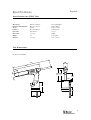 5
5
-
 6
6
-
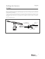 7
7
-
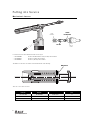 8
8
-
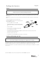 9
9
-
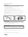 10
10
-
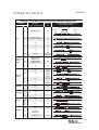 11
11
-
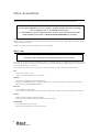 12
12
-
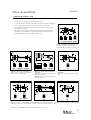 13
13
-
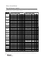 14
14
-
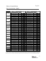 15
15
-
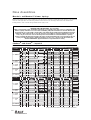 16
16
-
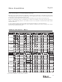 17
17
-
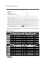 18
18
-
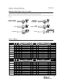 19
19
-
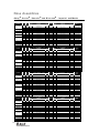 20
20
-
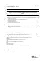 21
21
-
 22
22
-
 23
23
-
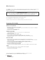 24
24
-
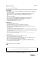 25
25
-
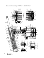 26
26
-
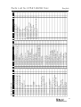 27
27
-
 28
28
-
 29
29
-
 30
30
-
 31
31
-
 32
32
-
 33
33
-
 34
34
-
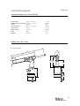 35
35
-
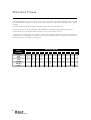 36
36
-
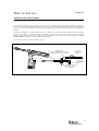 37
37
-
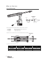 38
38
-
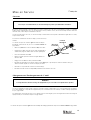 39
39
-
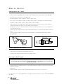 40
40
-
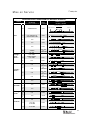 41
41
-
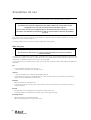 42
42
-
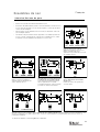 43
43
-
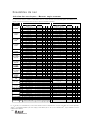 44
44
-
 45
45
-
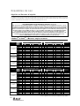 46
46
-
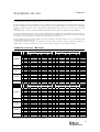 47
47
-
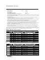 48
48
-
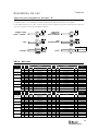 49
49
-
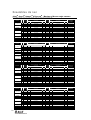 50
50
-
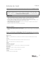 51
51
-
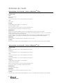 52
52
-
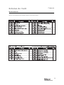 53
53
-
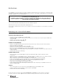 54
54
-
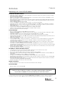 55
55
-
 56
56
-
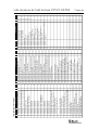 57
57
-
 58
58
-
 59
59
-
 60
60
-
 61
61
-
 62
62
-
 63
63
-
 64
64
-
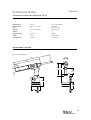 65
65
-
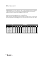 66
66
-
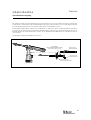 67
67
-
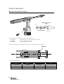 68
68
-
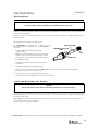 69
69
-
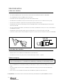 70
70
-
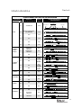 71
71
-
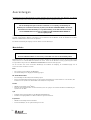 72
72
-
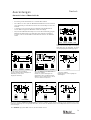 73
73
-
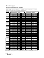 74
74
-
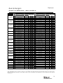 75
75
-
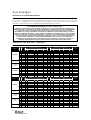 76
76
-
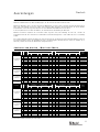 77
77
-
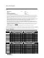 78
78
-
 79
79
-
 80
80
-
 81
81
-
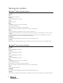 82
82
-
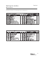 83
83
-
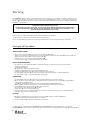 84
84
-
 85
85
-
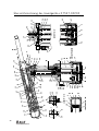 86
86
-
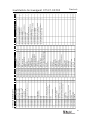 87
87
-
 88
88
-
 89
89
-
 90
90
-
 91
91
-
 92
92
-
 93
93
-
 94
94
-
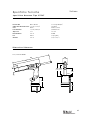 95
95
-
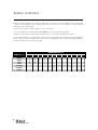 96
96
-
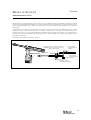 97
97
-
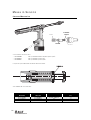 98
98
-
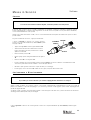 99
99
-
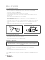 100
100
-
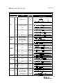 101
101
-
 102
102
-
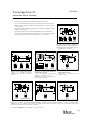 103
103
-
 104
104
-
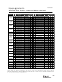 105
105
-
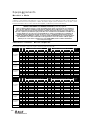 106
106
-
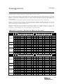 107
107
-
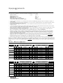 108
108
-
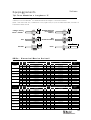 109
109
-
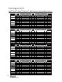 110
110
-
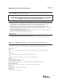 111
111
-
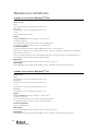 112
112
-
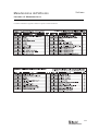 113
113
-
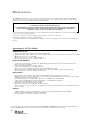 114
114
-
 115
115
-
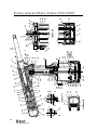 116
116
-
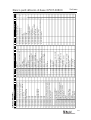 117
117
-
 118
118
-
 119
119
-
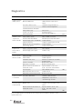 120
120
-
 121
121
-
 122
122
-
 123
123
-
 124
124


Avdel 07537 Manuale del proprietario
- Categoria
- Utensili elettrici
- Tipo
- Manuale del proprietario
in altre lingue
- English: Avdel 07537 Owner's manual
- français: Avdel 07537 Le manuel du propriétaire
- Deutsch: Avdel 07537 Bedienungsanleitung
Documenti correlati
Altri documenti
-
Stanley 07536 Manuale utente
-
Stanley AV15 Manuale utente
-
Stanley AV30 Manuale utente
-
Stanley 76002 Manuale utente
-
Makita DRV150 Manuale utente
-
DeLOCK 65922 Scheda dati
-
Beta 1742A Istruzioni per l'uso
-
STIEBEL ELTRON Beilage Schlauchverschraubung Operation Instruction
-
Facom Y.135F Manuale del proprietario
-