
Model CW5-37A
TECHNICAL HANDBOOK
Manual No. 513812

Montapanna automatico - Automatic cream-whipper - Machine automatique à Chantilly
CW5 - 37a (BETA 5) [S.1] Automatischer Schlagsahnebereiter - Monta-nata automático
2
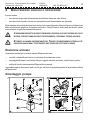
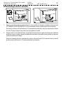
ATTENZIONE:
Il presente Libretto tecnico stato redatto per fornire le seguenti informazioni tecniche,
specifiche del modello da Voi acquistato:
1 - Caratteristiche tecniche
2 - Schema Elettrico
3 - Schema Frigorifero
4 - Manutenzione annuale e riparazione
5 - Ordinazione Ricambi.
Pertanto, nel caso fosse necessario un intervento del Servizio Assistenza, Vi raccoman-
diamo di fornire il presente Libretto Tecnico al personale tecnico dell'Assistenza, unita-
mente all'apparecchio.
IL PRESENTE LIBRETTO TECNICO NON AUTORIZZA COMUNQUE L'UTENTE AD EFFETTUARE AUTO-
NOMAMENTE LE OPERAZIONI DI RIPARAZIONE E/O MANUTENZIONE.
TUTTE LE OPERAZIONI DEVONO ESSERE EFFETTUATE CON IL CAVO DI ALIMENTAZIONE SCOLLEGA-
TO, ECCETTO QUELLE IN CUI È DIVERSAMENTE ED ESPRESSAMENTE SPECIFICATO.
L'utente deve effettuare esclusivamente gli interventi descritti nelle ISTRUZIONI PER
L'USO.

Libretto tecnico - Technical handbook - Livret technique Z16.097 A
Technisches Heft - Libreto técnico 0699-V04-CEE CW5 - 37a (BETA 5) [S.1]
3
ATTENTION:
Ce Livret Technique a été rédigé afin d’in-
diquer les information techniques suivan-
tes:
1 - Caractéristiques techniques
2 - Schéma électrique
3 - Schéma frigorifique
4 - Manutention annuelle et réparation
5 - Commande pices détachées.
S’il était nécessaire donc une intervention
du Service Assistance, nous Vous con-
seillons de donner ce Livret Technique avec
l’appareil au technicien de l’Assistance.
CE LIVRET TECHNIQUE N’AUTORISE
AUCUNE OPÉRATION DE RÉPARATION ET
/
OU MANUTENTION EFFECTUÉE PAR L’USA-
GER.
TOUTES LES OPÉRATIONS DOIVENT ÊTRE
EFFECTUÉES AVEC LE CÂBLE D
’ALIMEN-
TATION SÉPARÉ, SAUF QUAND SOIT IN-
DIQUÉE AUTREMENT.
L’usager doit effectuer seulement les inter-
ventions indiquées dans le livret «NOTICE
D’UTILISATION» .
WARNING:
This Technical Handbook has been drafted
to provide the technical information relevant
specifically to your device:
1 - Technical data
2 - Electrical diagram
3 - Refrigerating diagram
4 - Yearly aintenance and repairing
5 - Spares ordering.
So, if Service is needed, we recommend
you to give this Technical Handbook to the
Service technician together with the device.
IN ANY CASE, THIS TECHNICAL HAND-
BOOK DON'T PERMIT THE USER TO PER-
FORM ANY MAINTENANCE AND REPAIR-
ING PROCEDURES ON HIS OWN.
EVERY PROCEDURE MUST BE PERFORMED
AFTER HAVING DISCONNECTED THE
POWER SUPPLY CABLE
, EXCEPT WHERE
IS EXPRESSLY OTHERWISE SPECIFIED
.
The user must perform the procedures de-
scribed in the “OPERATING INSTRUC-
TION” handbook only.

Montapanna automatico - Automatic cream-whipper - Machine automatique à Chantilly
CW5 - 37a (BETA 5) [S.1] Automatischer Schlagsahnebereiter - Monta-nata automático
4
ATENCIÓN:
Este Libreto Técnico sirve para proporcio-
nar las siguientes informaciones técnicas,
especificas del modelo que Uds. han com-
prado:
1 - Características técnicas
2 - Esquema eléctrico
3 - Esquema frigorífico
4 - Manutención anual y reparación
5 - Pedido Piezas de recambios.
Por eso, si una intervención del Servicio
Asistencia fuera necesaria, Les asesora-
mos dar este Libreto Técnico al personal
técnico de la Asistencia, junto al aparato.
ESTE LIBRETO TÉCNICO NO AUTORIZA
SIN EMBARGO EL USUARIO A EFECTUAR
AUTÓNOMAMENTE LAS OPERACIONES DE
REPARACIÓN Y
/O DE MANUTENCIÓN.
TODAS LAS OPERACIONES TIENEN QUE
SER CUMPLIDAS CON EL CABLE DE
ALIMENTACION DESCONECTADO
, EXCEP-
TO LAS EN QUE ESTÁ INDICADO CLARA-
MENTE.
El usuario tiene que cumplir exclusivamen-
te las intervenciones indicadas en el libreto
“MODO DE EMPLEO”.
ZUR BEACHTUNG
Diese Technische Anleitung enthält die fol-
genden Informationen über das von Ihnen
erworbene Gerät:
1 - Technische Eigenshaften
2 - Schaltplan
3 - Kühlschema
4 - Jährliche Wartung und Reparatur
5 - Bestellung vor Ersatzteilen.
Deswegen empfehlen wir Ihnen, bei jedem
Kundendiensteinsatz dem Kundendienst-
techniker die Technische Anleitung zusam-
men mit dem Gerät auszuhändigen.
DIESE TECHNISCHE HEFT ERMÄCHTIGT
DEN
BENUTZER NICHT, SELBSTSTÄNDIG
REPARATUREN ODER WARTUNGS-
ARBEITEN DURCHZUFUHREN.
ALLE ARBEITEN DÜRFEN NUR DURCHGE-
FÜHRT WERDEN, WENN DAS VERSOR-
GUNGSKABEL VOM NETZ GETRENNT IST.
AUSNAHME: JENE ARBEITEN, BEI DE-
NEN AUSDRÜCKLICH DIE STROMVERSOR-
GUNG ERFORDERLICH IST.
Der Benutzer darf nur die in der BEDIE-
NUNGSANLEITUNG beschriebenen Arbei-
ten ausführen.

Libretto tecnico - Technical handbook - Livret technique Z16.097 A
Technisches Heft - Libreto técnico 0699-V04-CEE CW5 - 37a (BETA 5) [S.1]
5
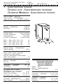
1CARATTERISTICHE TECNICHE
TECHNICAL DATA - CARACTÉRISTIQUES TECHNIQUES
TECHNISCHE MERKMALE - CARACTERÍSTICAS TÉCNICAS
Codice del modello - Model code
Code du modle - Modellbezeichnung
Código del modelo 730 BETA5 A [XXXX*] 1
(TC_093)
Dimensioni - Dimensions L=250 mm
Dimensions - Abmessungen P=450 mm
Dimensiones H=400 mm
P2=157 mm
[*] Tensione di alimentazione Corrente nominale
[*] Supply voltage Current absorption
[*] Tension d’alimentation Courant nominal
[*] Stromspannung Stromstärke
[*] Tensión de alimentación Corriente nominal
[2251] = 220V~ (±10%) 50 Hz (1N) 4 A
[2261] = 220V~ (±10%) 60 Hz (1N) 5 A
[1151] = 110V~ (±10%) 50 Hz (1N) 7 A
[1161] = 115V~ (±10%) 60 Hz (1N) 7 A
Potenza assorbita - Power input
Puissance absorbie - Leistungsabnahme
Potencia absorbida 400 W
Capacità bacinella (estraibile)
Cream container capacity (removable)
Capacité de la cuvette (retirable)
Inhalt des Sahnebehälters (herausnehmbar)
Cabida cubita (sacable) 5 lt
Peso netto - Net weight
Poids net - Nettogewicht
Peso neto 30 Kg
Condensazione - Condensation Aria - A i r
Condensation - Kondensation Air - Luft
Condensación Aire
Gas frigorifero (tipo e quantità)
Refrigerating gas (type and quantity)
Gaz frigorifique (type et quantité) R 134a
Kühlgas (Art und Menge) 130 g (50 Hz)
Gas frigorífico (tipo y cantidad) 100 g (60 Hz)
Olio anticongelante - Anti- freezing oil
Huile antigel - Kältbeständiges Öl - RL 32 S
Aceite congelador - ISO VG 22 (ESTER)
PRESSIONI E TEMPERATURE
PRESSUREAND TEMPERATURE
PRESSION ET TEMPERATURE
DRUCH UND TEMPERATUR
PRESIÓN Y TEMPERATURA
Ambiente - Room
Ambient - Umgebungstemperatur
Aire ambiente 25°C
Condensazione - Condensation
Condensation - Kondensation 9, 8…10, 3 Bar
Condensación +42…+45 °C
Evaporazione - Evaporation
Evaporation - Verdunstung 0, 2…0, 1 Bar
Evaporación –22…–25 °C

Montapanna automatico - Automatic cream-whipper - Machine automatique à Chantilly
CW5 - 37a (BETA 5) [S.1] Automatischer Schlagsahnebereiter - Monta-nata automático
6
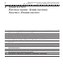
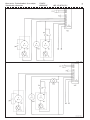
2SCHEMA ELETTRICO
ELECTRICAL DIAGRAM - SCHÉMA ÉLECTRIQUE
SCHALTBILD - ESQUEMA ELÉCTRICO
L1046A
CL Klixon (protezione termica) MC/MP – Klixon (thermal protection) MC/MP – Klixon (protection thermique) MC/MP – Klixon
(Überhitzungsschutz) MC/MP – Klixon (protección térmica) MC/MP
CMP Condensatore marcia MP – MP run capacitor – Condenseur marche MP – Kondensator MP (während Betrieb) – Condensador marcha MP
F Fusibile – Fuse – Fusible – Schmelzsicherungen – Fusible
MC Motore Compressore – Compressor motor – Moteur compresseur – Kompressormotor – Motor Compresor
MP Motore Pompa (con prot. termica interna) – Pump motor (with internal thermal protection) – Moteur pompe (avec protection thermique
interne) – Pumpenmotor (mit eingebautem Überhitzungsschutz) – Motor bomba (con protección térmica)
MSE Morsettiera Scheda Elettronica – Electronic card terminals – Borne de la fiche électronique – Klemmverbindung für Schaltkarte – Borne
ficha electrónica
MVC Motore Ventilatore – Fan motor – Moteur ventilateur – Ventilatormotor – Motor ventilador
N Neutro – Neutral – Neutre – Nulleiter – Neutro
PD Pedaliera Erogazione (opzionale) – Dispensing foot control (optional) – Pédale de distribution (optionnel) – Fußschalter für Lieferung (extra) –
Pedal de distribución (opcional)
R Fase – Live – Phase – Phase – Fase
RA Relè Avviamento motore compressore – Compressor motor starting relay – Relais mise en train moteur compresseur – Relais zum
Starten des Kompressormotors – Relé puesta en marche compresor
STP Sonda Temperatura – Temperature probe – Sonde température – Temperatursensor – Sonda temperatura
TR Trasformatore – Transformer – Transformateur – Transformator – Transformador

Libretto tecnico - Technical handbook - Livret technique Z16.097 A
Technisches Heft - Libreto técnico 0699-V04-CEE CW5 - 37a (BETA 5) [S.1]
7

Montapanna automatico - Automatic cream-whipper - Machine automatique à Chantilly
CW5 - 37a (BETA 5) [S.1] Automatischer Schlagsahnebereiter - Monta-nata automático
8
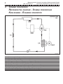
3SCHEMA FRIGORIFERO
REFRIGERATING DIAGRAM - SCHÉMA FRIGORIFIQUE
KÜHLSCHEMA - ESQUEMA FRIGORÍFICO
L2016A
CA Condensatore ad aria – Air condenser – Condenseur à aire – Luftkondensator – Condensador a aire
E Evaporatore – Evaporator – Evaporateur – Verdunster – Vaporizador
FL Filtro – Filter – Philtre – Filter – Filtro
MC Motocompressore – Compressor – Motocompresseur – Kompressor – Motocompresor
MSE Scheda Elettronica – Electronic card – Fiche électronique – Schaltkarte – Ficha electrónica
MVC Ventilatore – Fan – Ventilateur – Ventilator – Ventilador
STP Sonda Temperatura – Temperature probe – Sonde température – Temperatursensor – Sonda temperatura
TC Capillare – Capillary tube – Capillaire – Kapillaren – Capilar
GAS Circuito frigorifero – Refrigerating circuit – Ligne frigorifique – Kühlkreis – Línea frigorífica
ELE Circuito elettrico – Electrical circuit – Ligne électrique – Schaltkreis – Línea eléctrica

Libretto tecnico - Technical handbook - Livret technique Z16.097 A
Technisches Heft - Libreto técnico 0699-V04-CEE CW5 - 37a (BETA 5) [S.1]
9
4MANUTENZIONE ANNUALE E RIPARAZIONE
In questa sezione:
— sono elencate le operazioni di manutenzione da effettuare almeno una volta all'anno;
— sono descritte le procedure corrette per i principali interventi di manutenzione e/o riparazione.
Resta comunque inteso che le descrizioni sono fornite al solo scopo di agevolare il lavoro del tecnico, che deve essere
dotato di attrezzatura specifica e di esperienza nel settore. Tutti gli interventi, anche quelli non descritti, devono
essere effettuati a regola d'arte da personale esperto.
LE OPERAZIONI DESCRITTE IN SEGUITO PREVEDONO L'ACCESSO ALLE PARTI INTERNE DELL'APPA-
RECCHIO, PERTANTO SONO DESTINATE ESCLUSIVAMENTE A PERSONALE TECNICO ABILITATO.
ATTENERSI ALLE NORME ANTINFORTUNISTICHE. TOGLIERE L'ALIMENTAZIONE ELETTRICA ALL'AP-
PARECCHIO QUANDO NON È STRETTAMENTE NECESSARIA PER EFFETTUARE LE PROVE.
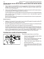
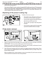
Revisione annuale
Le operazioni principali per la revisione annuale dell'apparecchio sono:
— controllo e pulizia delle parti interne, in particolare del condensatore ad aria;
— smontaggio della pompa e sostituzione delle parti soggette ad usura: guarnizioni, anello di tenuta, palette;
— verifica del corretto funzionamento dell'apparecchio in generale.
Le procedure seguenti descrivono il modo corretto per effettuare le principali operazioni di manutenzione richieste
dall'apparecchio.
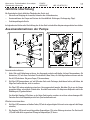
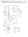
Smontaggio pompa
1
2

Montapanna automatico - Automatic cream-whipper - Machine automatique à Chantilly
CW5 - 37a (BETA 5) [S.1] Automatischer Schlagsahnebereiter - Monta-nata automático
10
SMONTAGGIO
1. Togliere il rubinetto, il canotto ed il labirinto, ed estrarre manualmente il tubo di aspirazione e la valvola dell'aria
completa. Svitare i dadi ciechi [27] con una chiave A TUBO da 8 mm, rimuovere le rondelle e togliere il coper-
chio [28]. Estrarre l'assieme pompa [3];
2. Togliere le palette [29] eventualmente utilizzando pinzette a molla o pinze a becchi sottili, facendo attenzione a
non perdere le mollette [30] che spingono le palette verso l'esterno.
Le palette [29] devono essere sostituite almeno una volta all'anno. Dopo avere estratto le palette dall'assieme
pompa, controllare che non siano danneggiate o eccessivamente usurate. I punti generalmente soggetti ad
usura sono indicati con [U].
Ruotare manualmente il giunto [44], verificando che non vi siano punti di sforzo e che non vi sia gioco percetti-
bile tra il rotore ed il corpo pompa.
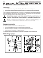
RIMONTAGGIO
2. Individuare il lato smussato di ciascuna paletta. Inserire le palette [29] complete di entrambe le mollette [30]
nell'assieme pompa [3] con lo smusso rivolto verso il basso;
1. Orientare correttamente il giunto [44] ed inserire il corpo pompa [3] nel suo supporto. Fare attenzione alla spina
di centraggio [43] che deve inserirsi nel foro apposito ricavato nel corpo pompa [3].
Controllare che la guarnizione [G] sia correttamente in sede ed inserire il coperchio pompa [28]. Avvitare par-
zialmente i dadi [27] interponendo le rondelle. Prima di serrarli, montare il labirinto, il canotto ed il rubinetto per
mantenere allineato meccanicamente il coperchio [28]. Serrare quindi ALTERNATIVAMENTE i dadi [27] con
chiave esagonale A TUBO da 8 mm. Reinserire la valvola dell'aria completa ed il tubo di aspirazione.
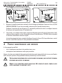
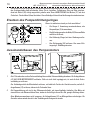
Sostituzione anello di tenuta pompa
Operazione da eseguire almeno una volta all'anno.
— Smontare la pompa seguendo la procedura relativa
ed estrarre il corpo pompa [3];
— Allentare il grano di fissaggio del mozzo [44] e toglie-
re il mozzo stesso ed il rotore della pompa;
— Togliere l'anello elastico (seeger) utilizzando un'ap-
posita pinza a becchi conici;
— Estrarre l'anello di tenuta della pompa [45]. Il nuovo
anello di tenuta dev'essere montato come mostrato
in figura.

Libretto tecnico - Technical handbook - Livret technique Z16.097 A
Technisches Heft - Libreto técnico 0699-V04-CEE CW5 - 37a (BETA 5) [S.1]
11
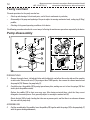
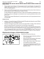
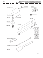
Smontaggio motore pompa
1
2
1. Rimuovere il pannello laterale destro svitando le 4 viti di fissaggio ed individuare il morsetto di terra [J2] SUL
CORPO DEL MOTORE. Se non fosse accessibile, rimuovere anche il pannello laterale sinistro;
Scollegare il connettore del cavo del motore [J1], annotando la posizione dei contatti, e scollegare il morsetto
di terra posto sul corpo del motore [J2] svitando la vite.
2. Tenere fermo, con un'idonea chiave inglese, il supporto della pompa posto nella vasca di refrigerazione. Utiliz-
zando una chiave a cinghia o a catena, da avvolgere attorno al corpo del motore, SVITARE il motore ruotandolo
con decisione nella direzione mostrata in figura.
In fase di rimontaggio del motore, ricordarsi di collegare il morsetto di terra [J2] al corpo del motore e control-
lare che i contatti del connettore [J1] siano posizionati correttamente.
4YEARLY MAINTENANCE AND REPAIRS
In this paragraph you will find:
— a list of maintenance operations to be carried out once a year;
— a description of main maintenance and/or repair procedures.
However, the above are intended to help experienced technical personnel using suitable tools to carry out all mainte-
nance and repair operations. Only specialized technical personnel may service the machine.
THE FOLLOWING OPERATIONS ENTAIL ACCESS INSIDE THE MACHINE, ONLY CERTIFIED TECHNICAL
PERSONNEL MAY ACCESS THE MACHINE
.
COMPLY TO ALL INDUSTRIAL INJURY LEGISLATION. CUT POWER OFF UNLESS POWER IS ABSO-
LUTELY NECESSARY TO CARRY OUT TESTS.

Montapanna automatico - Automatic cream-whipper - Machine automatique à Chantilly
CW5 - 37a (BETA 5) [S.1] Automatischer Schlagsahnebereiter - Monta-nata automático
12
Yearly overhaul
The main operations for the yearly overhaul are:
— Check-up and cleaning of the internal parts, and of the air condensator in particular;
— Disassembly of the pump and replacing of the parts subject to wearing: mechanical seals, sealing ring (V-Ring),
paddles;
— Checking of the general operating conditions of the device.
The following procedures describe the correct way of effecting the maintenance operations requested by the device.
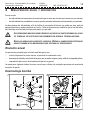
Pump disassembly
1
2
DISMANTLING
1. Remove the supply faucet, the labyrinth-tube and the labyrinth, and pull out the suction tube and the complete
air-inlet valve. Unscrew the nuts [27] by using an 8mm TUBE spanner, then remove the relevant washers and
the pump lid [28]. Remove the pump body [3].
2. Carefully extract the paddles [29] by using tapered-nose pliers, making sure not to lose the springs [30] that
tend to push the paddles outside;
Replace the paddles [29] at least once every year. After having extracted them, check that they are not
damaged or excessively worn. Parts generally subject to wearing are marked with [U].
Rotate the joint [44] by hand, checking that there are no pressure point, and that there is no clearance between
the rotor and the pump body.
ASSEMBLING
2. Find the rounded side of the paddles. Insert the paddles [29] together with the springs [30] in the pump body [3]
with the groove looking downwards;

Libretto tecnico - Technical handbook - Livret technique Z16.097 A
Technisches Heft - Libreto técnico 0699-V04-CEE CW5 - 37a (BETA 5) [S.1]
13
1. Properly align the joint [44] and insert the pump body [3] into its support. Check that the pin [43] matches the
relevant hole on the pump body [3].
Check that the O-Ring [G] is in place and insert the pump lid [28]. Partially screw the nuts [27] interposing the
washers. Before tightening them, install the labyrinth, the labyrinth-tube and the supply faucet, to keep the lid
[28] mechanically aligned. Then, ALTERNATELY tighten the nuts [27] by using an 8mm TUBE spanner. Rein-
stall the complete air-inlet valve and the suction tube.
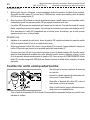
Replacing of the pump’s sealing ring
To be done at least once every year.
— Disassemble the pump following the relative proce-
dure and extract the entire body of the pump [3];
— Loosen the hub’s fixing grub screw [44] and take the
hub itself away with the pump’s rotor;
— Take the elastic ring (seeger) away using tapered-
nose pliers;
— Extract the pump’s sealing ring [45]. The new sealing
ring must be assembled as shown in the figure.
Pump motor removal
1
2
1. Remove the right lateral panel unscrewing the four fixing screws and find the earth buckle [J2] ON THE
MOTOR’S BODY. If this is not easily accessible, remove the left lateral panel also;
Disconnect the connector of the motor’s cable [J1], noting the contact’s position, and disconnect the earth
buckle positioned on the motor’s body [J2] unscrewing the screw.
2. Keep still the pump’s mounting, placed in the cooling tray, by using an appropriate monkey spanner. Using a
belt or chain key to be winded around the motor’s body, UNSCREW the motor by rotating it firmly in the
direction shown in the figure.
When reassembling the motor, always remember to connect the earth buckle [J2], with the motor and check
that the contacts of the connector [J1] are correctly positioned.

Montapanna automatico - Automatic cream-whipper - Machine automatique à Chantilly
CW5 - 37a (BETA 5) [S.1] Automatischer Schlagsahnebereiter - Monta-nata automático
14
4ENTRETIEN ANNUELLE ET RÉPARATION
Dans cette section:
— seront indiquées toutes les opérations d'entretien qu'il faut réaliser au moins une fois par an;
— seront indiquées toutes les procédures correctes afin de réaliser les interventions d'entretien et/ou de réparation.
Toutes les descriptions ont été données afin de faciliter la tâche au technicien qui doit avoir un équipement particulier
et une grande expérience dans le secteur. Toutes les interventions, même celles que nous n'avons pas indiquées,
doivent être réalisés par un technicien expert et dans les règles de l'art.
LES OPÉRATIONS QUE NOUS ALLONS DÉCRIRE, PRÉVOIENT L'ACCÈS AUX PARTES INTERNES DE
L
’APPAREIL. ELLES SONT DONC DESTINÉES SEULEMENT À UN PERSONNEL TECHNIQUE CERTIFIÉ.
SUIVEZ LES NORMES ANTI-ACCIDENTS DU TRAVAIL. QUITTEZ L'ALIMENTATION ÉLECTRIQUE DE
L
'APPAREIL QUAND ELLE N'EST PAS NÉCESSAIRE AFIN DE RÉALISER LES ESSAIS.
Révision annuelle
Les opérations principales pour la révision annuelle de l’appareil sont:
— contrôle et nettoyage des partes internes, en particulier du condenseur à aire;
— démontage de la pompe et remise des parties usées: joints, bague d’étanchéité, palles;
— révision du correct fonctionnement de l’appareil en général.
Les indications suivants décrivent la façon correcte de réaliser les principales opérations de manutention.
Démontage pompe
1
2

Libretto tecnico - Technical handbook - Livret technique Z16.097 A
Technisches Heft - Libreto técnico 0699-V04-CEE CW5 - 37a (BETA 5) [S.1]
15
DÉMONTAGE
1. Enlevez le robinet, le porte-chicane et la chicane et tirez à la main le tuyau d’aspiration et la soupape de l’air
complète. Dévisser les écrous [27] avec une clef A TUYAU de 8 mm, remuez les rondelles et enlevez le couvercle
[28]. Tirez l’ensemble pompe [3];
2. Enlevez les palles [29] utilisant des pincettes à ressorts ou des pincettes à becs minces, faisant attention a ne
perdre pas les petits ressorts [30] que poussent les palles à l’extérieur.
Les palles [29] doivent être remplacées une fois par an. Après avoir tiré les palles de l’ensemble pompe, contrô-
lez qu’elles ne soient pas endommagées ou excessivement usées. Les parties généralement usées sont indi-
quées avec [U].
Tournez à la main le moyeu [44] vérifiant qu’il n’y a pas de point de contact et qu’il n’y a pas de jeu entre le rotor
et le corps pompe.
REMONTAGE
2. Individuez le côte arrondi de chaque palle. Mettez les palles [29] complètes des deux petits ressorts [30] dans
l’ensemble pompe [3] avec l’arrondissage vers le bas;
1. Positionnez correctement le moyeu [44] et mettez le corps pompe [3] dans son support. Faites attention au
goujon de centrage [43] que doit s’introduire dans le trou spécial dans le corps pompe [3].
Contrôlez que le joint [G] soit correctement dans sa place et introduisez le couvercle pompe [28], Vissez douce-
ment les écrous [27] interponant les rondelles Avant de les serrer, montez la chicane, le porte-chicane et le
robinet afin de garder bien aligné le couvercle Serrez donc ALTERNATIVEMENT les écrous [27] avec une clef
hexagonale A TUYAU de 8 mm. Introduisez de nouveau la soupape de l’air complète et le tuyau d’aspiration.
Replacement bague d’étanchéité pompe
Opération qu’il faut suivre une fois par an.
— Dévissez la pompe suivant les indications relatives et
tirez le corps pompe [3];
— Desserrez la mise en place du moyeu [44] et enlevez
le moyeu même et le rotor de la pompe;
— Enlevez la bague élastique (seeger) utilisant une pin-
cette spéciale avec des becs coniques;
— Tirez la bague d’étanchéité de la pompe [45]. La nou-
velle bague d’étanchéité doit être montée comme ex-
pliqué dans le dessin.

Montapanna automatico - Automatic cream-whipper - Machine automatique à Chantilly
CW5 - 37a (BETA 5) [S.1] Automatischer Schlagsahnebereiter - Monta-nata automático
16
Démontage moteur pompe
1
2
1. Remuez le panneau latéral de droite en dévissant le quatre vis de mise en place; repérez l’étau de terre SUR LE
CORPS DU MOTEUR [J2]. Si n'est pas possible d'y arriver, remuez aussi le panneau de gauche;
Séparez le connecteur du câble du moteur [J1] en annotant la position des contactes, et séparez l'étau de terre
[J2] sur le corps du moteur en dévissant sa vis.
2. Bloquez, avec une adéquate clef, le support de la pompe dans la baignoire de réfrigération. Utilisant une clef à
courroie ou à chaîne, que Vous devrez enrouler atour du corps moteur, dévissez le moteur en le tournant avec
décision dan la direction indiqué dans le dessin.
Pendant le remontage du moteur, souvenez-Vous de relier l’étau de terre [J2] au corps moteur et de contrôler
que les contactes di connecteur [J1] soient mise en place correctement.
4JÄHRLICHE WARTUNG UND REPARATUR
In diesem Abschnitt:
— sind die wenigstens einmal pro Jahr durchzuführenden Wartungsarbeiten aufgeführt;
— wird die korrekte Durchführung der wichtigsten Wartungsund/oder Reparaturarbeiten beschrieben.
Es versteht sich dabei von selbst, daß die folgenden Beschreibungen nur der Arbeitserleichterung des technischen
Personals dienen sollen, das über entsprechende Erfahrung auf diesem Gebiet und das geeignete Werkzeug verfügt.
Alle Arbeiten, auch die hier nicht beschriebenen, müssen von erfahrenem Personal sachgerecht ausgeführt werden.
DIE IM FOLGENDEN BESCHRIEBENEN TÄTIGKEITEN ERFORDERN DEN ZUGANG ZU DEN GERÄTE-
INNENTEILEN, SIE SIND DESHALB AUSSCHLIEßLICH QUALIFIZIERTEM TECHNISCHEN PERSONAL
VORBEHALTEN
.
BEACHTEN SIE DIE GELTENDEN UNFALLVERHÜTUNGSVORSCHRIFTEN. STROMVERSORGUNG DES
GERÄTS IMMER ABSCHALTEN, FALLS SIE FÜR DIE TESTS NICHT UNBEDINGT ERFORDERLICH IST.

Libretto tecnico - Technical handbook - Livret technique Z16.097 A
Technisches Heft - Libreto técnico 0699-V04-CEE CW5 - 37a (BETA 5) [S.1]
17
Jährliche Überholung
Die Hauptarbeiten bei der jährlichen Überholung des Geräts sind:
— Kontrolle und Reinigung der Innenteile, besonders des Luftkondensators;
— Auseinanderbauen der Pumpe und Ersetzen der Verschleißteile: Dichtungen, Dichtungsring, Flügel;
— Funktionsprüfung des Geräts.
Im folgenden wird die korrekte Durchführung der für das Gerät erforderlichen Hauptwartungsarbeiten beschrieben.
Auseinandernehmen der Pumpe
1
2
Auseinandernehmen
1. Hahn, Rohr und Schlagkamm entfernen, das Ansaugrohr und das vollständige Luftventil herausnehmen. Die
Hutmuttern [27] mit einem Sechskant-Steckschlüssel (8mm) lösen, die Unterlegscheiben entfernen und den
Deckel [28] abnehmen. Die ganze Pumpe [3] herausnehmen;
2. Die Flügel [29] herausnehmen, evtl, mit Hilfe einer Feder- oder Flachzange, dabei darauf achten, die Federn, die
Flügel nach außen drücken, nicht zu verlieren.
Die Flügel [29] müssen mindestens einmal pro Jahr ausgewechselt werden. Nachdem Sie sie aus der Pumpe
genommen haben, auf mögliche Schäden bzw. Verschleiß untersuchen. Die Hauptverschleißpunkte sind in der
Abbildung mit [U] gekennzeichnet.
Von Hand die Kupplung [44] drehen, es darf keine Punkte geben, an denen sie sich nur schwer bewegen läßt.
Zwischen Rotor und Pumpenkörper darf kein Spiel wahrnehmbar sein.
Wiederzusammenbau
2. Die Flügel [29] zusammen mit beiden Federn [30] mit der abgeschrägten Seite nach unten zeigend in die Pumpe
einsetzen;
1. Die Kupplung [44] korrekt ausrichten und den Pumpenkörper [3] in seine Halterung einsetzen. Der Zentrierstift
[43] muß in die dafür vorgesehene Öffnung im Pumpenkörper [3] fassen.

Montapanna automatico - Automatic cream-whipper - Machine automatique à Chantilly
CW5 - 37a (BETA 5) [S.1] Automatischer Schlagsahnebereiter - Monta-nata automático
18
Den korrekten Sitz der Dichtungen [C] kontrollieren und den Pumpendeckel [28] einsetzen. Die Muttern [27] mit
den Unterlegscheiben halb anschrauben. Bevor Sie sie festziehen, Schlagkamm, Rohr und Hahn einsetzen,
damit der Deckel [28] richtig ausgerichtet gehalten wird. Dann ABWECHSELND die Muttern [27] mit dem
Sechskant- Steckschlüssel (8mm) festziehen. Das vollständige Luftventil und das Ansaugrohr wiedereinsetzen.
Ersetzen des Pumpendichtungsringes
Dieses ist mindestens einmal pro Jahr auszuführen!
— Die Pumpe lt. Anweisung auseinanderbauen, den
Pumpenkörper [3] herausnehmen;
— Den Befestigungszapfen der Nabe [44] lösen und Nabe
und Rotor entfernen;
— Den Kolbenring (Seeger) mit einer Rundzange entfer-
nen;
— Den Dichtungsring [45] entfernen. Den neuen Dich-
tungsring lt. Abbildung einsetzen.
Auseinanderbauen des Pumpenmotors
1
2
1. Die 4 Schrauben der rechten Seitenverkleidung lösen und die Seitenverkleidung abnehmen. Die Erdungsklemme
[J2] AUF DEM MOTORGEHÄUSE auffinden. Sollte sie nicht leicht zugängig sein, ist auch die linke Seiten-
verkleidung zu entfernen.
Das Verbindungsstück des Motorkabels entfernen, sich dabei die Position der Kontakte merken, und die Er-
dungsklemme [J2] entfernen, indem sie die Schrauben lösen.
2. Die Pumpenhalterung, die sich in der Kältewanne befindet, mit einem Engländer festhalten. Den Motor mit
einem Ketten- oder Riemenschlüssel lösen, indem sie ihn kräftig in die auf der Abb. gezeigte Richtung drehen.
Beim Wiederzusammenbauen nicht vergessen, die Erdungsklemme [J2] am Motorgehäuse zu befestigen. Die
Kontakte müssen wieder korrekt in das Verbindungsstück eingesetzt werden.

Libretto tecnico - Technical handbook - Livret technique Z16.097 A
Technisches Heft - Libreto técnico 0699-V04-CEE CW5 - 37a (BETA 5) [S.1]
19
4MANUTENCIÓN ANUAL Y REPARACIÓN
En esta sección:
— han sido indicadas las operaciones de manutención que se tienen que efectuar por lo menos una vez cada año;
— han sido indicados los procedimientos correctos para las principales intervenciones de manutención y/o reparación.
Las descripciones han sido indicadas al fin de facilitar la intervención del técnico, que tendrá que tener todos los
aparejos específicos y mucha experiencia en el sector. Todas las intervenciones, también las que no han sido indica-
das, tienen que ser efectuada por un personal experto y a raja tabla.
LAS OPERACIONES INDICADAS AHORA PREVEEN EL ALCANZAR LAS PARTES INTERNAS DEL APARA-
TO; TIENEN QUE SER EFECTUADAS EXCLUSIVAMENTE POR PERSONAL TÉCNICO HABILITADO.
SIGAN LAS NORMAS ANTI-ACCIDENTES LABORALES. QUITAR LA ALIMENTACIÓN ELÉCTRICA DEL
APARATO CUANDO NO ES INDISPENSABLE PARA EFECTUAR LAS VERIFICACIONES
.
Revisión anual
Las operaciones principales para la revisión anual del aparato son:
— control y limpieza de las partes internas, en particular de condensador a aire;
— desmontaje de la bomba y sustitución de las partes que se puedan estropear: juntas, anillo de estanquedad, paletas;
— comprobación del correcto funcionamiento del aparato en general.
Las operaciones siguientes indican la manera correcta para efectuar las principales operaciones de manutención
necesarios al aparato.
Desmontaje bomba
1
2

Montapanna automatico - Automatic cream-whipper - Machine automatique à Chantilly
CW5 - 37a (BETA 5) [S.1] Automatischer Schlagsahnebereiter - Monta-nata automático
20
DESMONTAJE
1. Quitar el grifo, el barca y el laberinto, y sacar manualmente el tubo de aspiración y la válvula del aire completa.
Destornillar los dados ciegos [27] con una llave A TUBO de 8 mm, remover las arandelas y quitar la tapadera
[28]. Sacar el conjunto bomba [3];
2. Quitar las paletas [29] utilizando en caso de necesidad unas pinzas a muelle o pinzas con extremidades sutiles,
cuidando de no perder los pequeños muelles [30] que empujan las paletas hacia fuera.
Las paletas [29] tienen que ser reemplazados por lo menos una vez cada año. Tras haberlas sacado del conjunto
bomba, comprobar que no estén estropeadas. Las partes que de costumbre se estropean están indicados con [U].
Girar manualmente el cubito [44] comprobando que no existan puntos de esfuerzo y que no esté presente
vagancia entra el rotor y el cuerpo bomba.
REMONTAJE
2. Individuar la cara redonda de cada paleta. Inserir las paletas [29] completas de ambos los pequeños muelles
[30] en el conjunto bomba [3] con la cara redonda hacia abajo;
1. Dirigir correctamente el cubito [44] y inserir el cuerpo bomba [3] en su sostén. Tengan cuidado a la clavija para
centrar [43] que tiene que inserirse en el apropiado agujero del cuerpo bomba [3].
Controlar que la junta [G] esté correctamente en su lugar y inserir la tapadera bomba [28]. Atornillar parcial-
mente los dadas poniendo las arandelas entra ellos. Antes de cerrarlos, montar el laberinto, el barca y el grifo
al fin de mantener alineada mecánicamente la tapadera [28]. Cerrar entonces ALTERNATIVAMENTE los dos
dados [27] con llave hexagonal A TUBO de 8 mm. Reinserir entonces la válvula del aire completa y el tubo de
aspiración.
Sustitución anillo estanquedad bomba
Operación que se tiene que cumplir por lo menos una
vez cada año:
— Desmontar la bomba siguiendo las indicaciones rela-
tivas y sacar el cuerpo bomba [3];
— Destornillar el fijamiento del cubito [44] y sacar el
cubito mismo y el rotor de la bomba;
— Quitar el anillo elástico (seeger) utilizando una apro-
piada pinza con extremidad cónicas;
— Sacar el anillo de estanquedad [45] de la bomba. El nuevo anillo de estanquedad tiene que ser montado como
indicados en el dibujo.
La pagina si sta caricando...
La pagina si sta caricando...
La pagina si sta caricando...
La pagina si sta caricando...
La pagina si sta caricando...
La pagina si sta caricando...
La pagina si sta caricando...
La pagina si sta caricando...
-
 1
1
-
 2
2
-
 3
3
-
 4
4
-
 5
5
-
 6
6
-
 7
7
-
 8
8
-
 9
9
-
 10
10
-
 11
11
-
 12
12
-
 13
13
-
 14
14
-
 15
15
-
 16
16
-
 17
17
-
 18
18
-
 19
19
-
 20
20
-
 21
21
-
 22
22
-
 23
23
-
 24
24
-
 25
25
-
 26
26
-
 27
27
-
 28
28


Stoelting CW5-37B Technical Handbook
- Tipo
- Technical Handbook
- Questo manuale è adatto anche per
in altre lingue
- English: Stoelting CW5-37B
- français: Stoelting CW5-37B
- español: Stoelting CW5-37B
- Deutsch: Stoelting CW5-37B
Altri documenti
-
Albrecht TelMe Manuale del proprietario
-
Hendi 588017 Manuale utente
-
Vogue CB162 Manuale utente
-
-
Taylor C004 - C007 Manuale utente
-
-
-
Sanremo Treviso LX Manuale del proprietario
-
Sabiana Carisma Fly CVP Installation, Use And Maintenance Manual
-
Ugolini ARCTIC DELUXE Manuale utente