
MÁQUINA DUPLICADORA DAKAR
Manual de instrucciones
KEY CUTTING MACHINE DAKAR
Instruction manual
KOPIERMASCHINE DAKAR
Anweisungshandbuch
MACCHINA DUPLICATRICE DAKAR
Manuale d’istruzione
MACHINE A TAILLER LES CLES DAKAR
Notice d'utilisation
MÁQUINA DUPLICADORA DAKAR
Manual de instruções

3.2.5 Cutting WIN-1D, WIN-2D, WIN-3D 11
and WIN-4D
type
keys
3.2.6 Cutting JIS-4.P type keys 12
3.2.7 Cutting FIC-2 and FIC-3 type keys 12
3.2.8 Cutting tubular type keys 12
3.2.9 Cutting FO-6.P type keys 12
3.2.10 Cutting MCM-10 type keys 12
3.2.11 Cutting KE-1 type key 12
3.2.12 Cutting TE-T60 and TE-T80 12
4. Maintenance and safety
4.1 Replacing the belt 13
4.2 Replacing the light 13
4.3 Replacing fuses 13
4.4 Safety recommendations 13
5. Accessories
5.1 Basic accessories 13
5.2 List of accessories for cutting certain models of key 13
6. Figure
1. Vorstellung und allgemeine gesichtspunkte
1.1
Allgemeines 14
1.2 Transport und verpackung 14
1.3 Kennzeichnungsaufkleber 14
2. Eigenschaften der maschine
2.1 Schlüsselfamilien 14
2.2 Hauptelemente der maschine 14
2.3 Technische daten 14
2.4 Komponenten und funktionsteile 15
2.4.1 Elektrischer stromkreis 15
2.4.2 Kalibriertastatur 15
2.4.3 Spannbacken 15
2.4.4 Feder und blockierung des schlittens
auf der "x-achse" 15
2.4.5 Elastischer oder blockierter taster 15
2.4.6 Vertikale Regelung des Fühlers 15
2.4.7 Wechseln von fräser und taster 15
2.4.8 Schalter des lichtes und
geschwindigkeitsauswählen den des motors
15
2.4.9 Hebel für röhrenförmige schlüssel 15
3. Betriebsfähigkeit und funktionsweise
3.1 Einstellung und inbetriebnahme 16
3.1.1 Einstellung der schneidtiefe 16
3.1.2 Flexibilität des tasters 16
3.2 Anfertigung von nachschlüsseln 16
3.2.1 Anfertigung von nachschlüsseln SEA-1 16
3.2.2 Anfertigung von nachschlüsseln typ 16
OP-WH.P und OP-WY.P
3.2.3 Anfertigung von nachschlüsseln typ ME-3.P 16
und ME-4.P
3.2.4 Anfertigung von nachschlüsseln typ KA-2, 16
KA-3 und KA-4
3.2.5 Anfertigung von nachschlüsseln typ
WIN-1D, 16
WIN-2D, WIN-3D
und WIN-4D
3.2.6 Anfertigung von nachschlüsseln typ JIS-4.P 17
3.2.7 Anfertigung von nachschlüsseln typ FIC-2 17
und FIC-3
3.2.8 Anfertigung von nachschlüsseln typ 17
rohrschlüssel
3.2.9 Anfertigung von nachschlüsseln typ FO-6.P 17
3.2.10 Anfertigung von nachschlüsseln MCM-10 17
3.2.11 Anfertigung von nachschlüsseln KE-1 17
3.2.12 Anfertigung von nachschlüsseln TE-T60 17
und TE-T80
4. Wartung und sicherheit
4.1 Auswechseln des riemens 18
5.1 Auswechseln der lampe 18
5.2
Auswechseln der sicherungen 18
5.3
Sicherheitsempfehlungen 18
5. Zubehöre
5.1 Grundzubehör 18
5.2
Zubehörliste zum schneiden einiger 18
bestimmter schlüsselmodelle
6. Abbildung
Indice / Index / Inhaltsverzeichnis / Indice / Indice / Index
1. Presentación y aspectos generales
1.1 Generalidades 4
1.2 Transporte y embalaje 4
1.3 Etiqueta identificadora 4
2. Características de la máquina
2.1 Familias de llaves 4
2.2 Elementos principales de la máquina 4
2.3 Datos técnicos 4
2.4 Componentes y partes funcionales 5
2.4.1 Circuito eléctrico 5
2.4.2 Teclado de control de calibrado 5
2.4.3 Mordazas 5
2.4.4
Muelle y bloqueo del carro en el eje “ x “ 5
2.4.5 Palpador elástico o bloqueo 5
2.4.6 Regulación vertical del palpador 5
2.4.7 Cambio de fresa y palpador 5
2.4.8
Interruptor de la luz y selector de
velocidad
del motor
5
2.4.9 Palanca para llaves tubulares 5
3. Operatividad y funcionamiento
3.1 Regulación y puesta a punto 6
3.1.1 Ajuste de la profundidad de corte 6
3.1.2 Flexibilidad del palpador 6
3.2 Duplicado de llaves 6
3.2.1 Duplicado de llaves SEA-1
3.2.2 Duplicado de llaves tipo OP-WH.P 6
y OP-WY.P
3.2.3 Duplicado de llaves tipo ME-3.P y ME-4.P 6
3.2.4 Duplicado de llaves tipo KA-2, KA-3 y KA-4 6
3.2.5 Duplicado de llaves tipo WIN-1D,WIN-2D,
WIN-3D y WIN-4D
6
3.2.6 Duplicado de llaves tipo JIS-4.P 7
3.2.7 Duplicado de llaves tipo FIC-2 y FIC-3 7
3.2.8 Duplicado de llaves tipo tubular 7
3.2.9 Duplicado de llaves tipo FO-6.P 7
3.2.10 Duplicado de llaves MCM-10 7
3.2.11 Duplicado de la llave KE-1 7
3.2.12 Duplicado de la llave TE-T60 y TE-T80 7
4. Mantenimiento y seguridad
4.1 Sustitución de la correa 8
4.2 Sustitución de la lámpara 8
4.3 Sustitución de los fusibles 8
4.4 Recomendaciones de seguridad 8
5. Accesorios
5.1 Accesorios base 8
5.2 Lista de accesorios para tallar algunos modelos 8
de llaves
6. Figura
1. Presentation and general aspects
1.1 General points 9
1.2 Transportation and packing 9
1.3 Identification label 9
2. Characteristics of the machine
2.1 Families of keys 9
2.2 Main elements of the machine 9
2.3 Technical data 9
2.4 Components and functional parts 10
2.4.1 Eectric circuit 10
2.4.2 Calibration keypad 10
2.4.3 Clamps
2.4.4 Springing and locking the slide on the “x” axis
10
2.4.5 Elastic or locked tracer point 10
2.4.6 Vertical adjustment of tracer point 10
2.4.7 Changing the milling cutter and tracer point
10
2.4.8 Speed and light switches 10
3. Operation
3.1 Adjustment and fine tuning 11
3.1.1 Adjusting the cutting depth 11
3.1.2 Tracer point flexibility 11
3.2 Cutting keys 11
3.2.1 Cutting SEA-1 keys 11
3.2.2 Cutting OP-WH.P and OP-WY.P type keys 11
3.2.3 Cutting ME-3.P and ME-4.P type keys 11
3.2.4 Cutting KA-2, KA-3 and KA-4 type keys 11
4
4-5
6-7
8
13
14
16-17
18
9-10
11-12
9-10
13
14-15
18
8
45
45
45

1. Presentazione e aspetto generale
1.1 Generalita' 19
1.2 Trasporto e imballaggio 19
1.3 Targhetta di identificazione 19
2. Caratteristiche della macchina
2.1 Tipi di chiavi 19
2.2 Elementi principali della macchina 19
2.3 Dati tecnici 19
2.4 Componenti e parti funzionali 20
2.4.1 Circuito elettrico 20
2.4.2 Tastiera di controllo della taratura elettronica 20
2.4.3 Morsetti 20
2.4.4 Molla e bloccagio del carrello sull’asse “x” 20
2.4.5 Tastatore elastico o bloccato 20
2.4.6 Regolazione verticale del tastatore 20
2.4.7 Cambio della fresa e tastatore 20
2.4.8 Interruttore della luce a selezioantore
della velocità del motore 20
2.4.9 Leva per chiavi tubolari 20
3. Operativitá e funzionamento
3.1 Regolazione e messa a punto della macchina 21
3.1.1 Controllo e regolazione della profondità
di taglio 21
3.1.2 Elasticità del tastatore 21
3.2 Duplicazione della chiave 21
3.2.1 Duplicazione chiavi tipo SEA-1 21
3.2.2 Duplicazione di chiavi tipo OP-WH.P e OP-WY.P 21
3.2.3 Duplicazione di chiavi tipo ME-3.P e ME-4.P 21
3.2.4 Duplicazione di chiavi tipo KA-2, KA-3 e KA-4 21
3.2.5 Duplicazione di chiavi tipo WIN-1D,
WIN-3D e WIN-4D 21
3.2.6 Duplicazione di chiavi tipo JIS-4.P 22
3.2.7 Duplicazione di chiavi tipo FIC-2 e FIC-3 22
3.2.8 Duplicazione di chiavi tipo TUBOLARI 22
3.2.9 Duplicazione di chiavi tipo FO-6P 22
3.2.10 Duplicazione di chiavi tipo MCM-10 22
3.2.11 Duplicazione di chiavi tipo KE-1 22
3.2.12 Duplicazione di chiavi tipo TE-T60 e TE-T80 22
4. Manutenzione e sicurezza
4.1 Sostituzione della cinghia 23
4.2 Sostituzione della lampada 23
4.3 Sostituzione dei fusibili 23
4.4 Raccomandazioni di sicurezza 23
5. Accessori
5.1 Accessori base 23
5.2 Elenco di accessori per tagliare alcuni
modelli di chiavi 23
6.- Esploso
1. Presentation et aspects generaux
1.1 Generalites 24
1.2 Transport et emballage 24
1.3 Plaque signaletique 24
2. Caracteristiques de la machine
2.1 Familles de cles 24
2.2 Elements principaux de la machine 24
2.3 Donnees techniques 24
2.4 Composants et parties fonctionnelles 25
2.4.1 Circuit electrique 25
2.4.2 Clavier de controle d’etalonnage 25
2.4.3 Mors 25
2.4.4 Systeme de ressort et blocage du chariot
25
sur l’axe “x”
2.4.5 Palpeur avec ressort (flexible) ou fixe 25
2.4.6 Reglage vertical du palpeur 25
2.4.7 Changement de fraise et de palpeur 25
2.4.8 Interrupteur lumiere et interrupteur 25
des vitesses du moteur
3. Fonctionnement et mise en service
3.1 Reglage et mise au point 26
3.1.1 Reglage de la profondeur de coupe 26
3.1.2 Ralpeur avec ressort 26
3.2 Reproduction de cles 26
3.2.1 Reproduction de la cle SEA-1 26
3.2.2 Reproduction des cles type OP-WH.P 26
et OP-WY.P
3.2.3 Reproduction des cles type ME-3.P 26
et ME-4.P
3.2.4 R
eproduction des cles type KA-2, 26
KA-3 et KA-4
3.2.5 Reproduction des cles type WIN-1D, 26
WIN-2D, WIN-3D et WIN-4D
3.2.6 Reproduction des cles type JIS-4.P 27
3.2.7 Reproduction des cles type 27
FIC-2 H, FIC-3H, FIC-4H et FIC-5H
3.2.8 Reproduction des cles type 27
tubulaire et a pompe francaises
3.2.9 Reproduction des cles type FO-6.P 27
3.2.10 Reproduction des cles de type MCM-10 27
3.2.11 Reproduction des cles de type KE-1 27
3.2.12 Reproduction de la cle TE-T60 27
et TE-T80
4. Entretien et securite
4.1 Remplacement de la courroie 28
4.2 Remplacement de la lampe 28
4.3 Remplacement des fusibles 28
4.4 Recommandations de securite 28
5. Accessoires
5.1 Accessoires de base 28
5.2 Liste des accessoires pour tailler certains 28
modeles de cles
6. Figure
1. Apresentação e aspectos gerais
1.1 Generalidades 29
1.2 Transporte e embalagem 29
1.3 Etiqueta identificadora 29
2. Características da máquina
2.1 Famílias de chaves 29
2.2 Elementos principais da máquina 29
2.3 Dados tecnicos 29
2.4 Componentes e partes funcionais 30
2.4.1 Circuito electrico 30
2.4.2 Teclado de controlo de calibrado 30
2.4.3 Mordaças 30
2.4.4 Efeito de mola e bloqueio do carro no 30
eixo “x”
2.4.5 Palpador elástico ou bloqueado 30
2.4.6 Regulação vertical do palpador 30
2.4.7 Mudança de fresa e de palpador 30
2.4.8 Interruptor da luz e selector de 30
velocidade do motor
3. Manuseio e funcionamento
3.1 Regulação e preparação 31
3.1.1 Ajuste da profundidade de corte 31
3.1.2 Flexibilidade do palpador 31
3.2 Duplicação de chaves 31
3.2.1 Duplicação da chave SEA-1 31
3.2.2 Duplicação de chaves tipo OP-WH.P e 31
OP-WY.P
3.2.3 Chaves tipo ME-3.P e ME-4.P 31
3.2.4 Duplicado das chaves KA-2, KA-3 e KA-4 31
3.2.5 Duplicação das chaves WIN-1D, WIN-3D 31
e WIN-4D
3.2.6 Chave JIS-4.P 32
3.2.7 Chaves tipo FIC-2 e FIC-3 32
3.2.8 Chaves tubulares 32
3.2.9 Chave tipo FO-6P 32
3.2.10 Duplicação da chave MCM-10 32
3.2.11 Duplicação da chave KE-1 32
3.2.12 Duplicação da chave TE-T60 e TE-T80 32
4. Manutenção e segurança
4.1 Substituíção da correia 33
4.2 Substituíção da lâmpada 33
4.3 Substituíção dos fusíveis 33
4.4 Recomendações de segurança 33
5. Acessórios
5.1 Acessórios base 33
5.2 Lista dos acessórios para executar alguns 33
modelos de chaves
6. Figura
19
28
19
21-22
23
23
24
24
26
28
29
29
31-32
33
33
45
45
45

4
Carro porta mordazas, ejes x - y
Cabezal, eje z
Mordaza basculante lado palpador
Mordaza basculante lado fresa
Pomo mordaza
Pomo bloqueo carro porta mordazas, eje x
Rueda de accionamiento del sistema de muelleo del carro, eje x
Maneta de bloqueo del palpador
Palanca de accionamiento y bloqueo cabezal eje z
Palanca de accionamiento de los carros, ejes x - y
Porta brocas, palpador y fresa
Palpador
Fresa
Interruptor general
Interruptor del motor, 2ª velocidades
Lámpara
Cajón de herramientas
Protección de virutas
Teclado y luces de calibración
Palanca de bloqueo de giro de mordazas
1
2
3
4
5
6
7
8
9
10
11
12
13
14
15
16
17
18
19
20
La máquina duplicadora DAKAR es de una gran preci-
sión y robustez. Se caracteriza por la mordaza que tiene
múltiples posibilidades distintas de sujeción de llaves sin
postizos ni adaptadores.
Ver Figura 2
Generalidades
y aspectos generales
1
Características
de la máquina
2
1.1
La máquina duplicadora DAKAR ha sido diseñada
teniendo en cuenta las normas de seguridad vigentes
en la C.E.E.
La seguridad del personal involucrado en el manejo
de este tipo de máquinas solo se consigue con un pro-
grama bien diseñado en seguridad personal, como la
implantación de un programa de mantenimiento y el
seguimiento de los consejos recomendados así como el
cumplimiento de las normas de seguridad que contem-
pla este manual.
Aunque la instalación de la máquina no presenta nin-
guna dificultad , es preferible que no intente instalar
, ajustar o manipular la misma sin leer primeramente
este manual.
La máquina sale de nuestra fabrica lista para el uso y
solo necesita operaciones de calibrado para los útiles
que se van a utilizar:
La máquina DAKAR duplica los siguientes tipos de llaves:
Llaves de puntos
Llaves de regata
Llaves tubulares
Llaves FIC-2 y FIC-3
Llaves WIN-1D, WIN-2D, WIN-3D y WIN-4D
Llaves JIS-4.P
Llaves FO-6.P
La máquina se presenta en el interior de un embalaje
de las dimensiones siguientes:
Ancho = 520 mm, larga = 575 mm, alto = 650mm y 30
Kg. de peso.
Cuando desembale la máquina, inspeccione cuidado-
samente por si hubiese sufrido algún daño en el trans-
porte. Si encuentra alguna anomalía, avise inmediata-
mente al transportista y no haga nada con la máquina
hasta que el agente del transportista haya realizado la
inspección correspondiente.
La máquina duplicadora DAKAR está provista de la
etiqueta identificadora , con especificación del numero
de serie, nombre y dirección del fabricante, marca CE y
año de fabricación. Ver figura 1.
Etiqueta identificadora
1.3
Transporte y embalaje
1.2
Familia de llaves
2.1
Motor : Monofásico 200 W. ,230 V - 50 Hz
Opcional: Monofásico 200W, 110V – 60Hz
Fresa : Acero super rápido
Velocidad fresa: 5500 y 8000 r.p.m.
Mordazas : De dos caras de sujeción y basculantes 0 / 45 º
Desplazamiento : En tres ejes con guías de bolas
Cursos útiles: Eje X = 60 mm, eje Y = 60 mm y eje Z = 40 mm
Alumbrado : Lámpara alógena de 50 vatios 240V
Dimensiones : Ancho = 310 mm, Profundidad = 380 mm y Alto = 420 mm
Peso : 25 Kg
Datos técnicos
2.3
Elementos principales de la máquina
2.2
Presentación
Español

2.4.6 Regulación vertical del palpador Ver Figura 8
Antes de poner la máquina en marcha con el interruptor
general , posicione en las mordazas las dos llaves , la ori-
ginal en la mordaza izquierda y la llave a duplicar en la
mordaza derecha .
Active el control electrónico presionando on / off del tecla-
do y efectúe la regulación de la manera siguiente:
• Gire 180ª grados la maneta de bloqueo (para blo-
quear el palpador )
• Baje el cabezal y apoye los útiles sin presionar sobre
una parte lisa de la llave
• Al contacto de los útiles con las llaves se dan las
siguientes situaciones.
Rojo izquierdo y derecho.
Si se encienden los dos rojos, la máquina esta regla-
da. Tocan la llave el palpador y la fresa.
Rojo izquierdo.
Si se enciende el rojo izquierdo, el palpador está
tocando la llave. Hay que reglarla. Para ello se gira
la rueda R en el sentido izquierdo hasta que se
enciendan las dos luces rojas.
Rojo derecho.
Si se enciende el rojo derecho, la fresa esta tocando
la llave. Hay que reglarla. Para ello se gira la rueda
R en el sentido derecho hasta que se enciendan las
dos luces rojas.
5
2.4.1 Circuito eléctrico Ver Figura 3
Los componentes principales del circuito eléctrico
y electrónico son los siguientes:
1
2
3
4
5
6
7
8
9
10
Toma de corriente: Filtro de red con fusible e interruptor.
Placa de conexiones : Base para las conexiones.
Interruptor de 3 posiciones: Marcha rápida,
parada y marcha lenta.
Lámpara : Alumbrado de la zona de trabajo
Motor : Monofásico con escobillas.
Encendido y apagado de lámparas: Pone en fun-
cionamiento la placa para el calibrado de la fresa
y apaga antes de empezar a duplicar llaves.
Placa de reglaje: Placa con dos lámparas rojas
para el calibrado de la fresa.
Fresa : Herramienta de corte para duplicar la
llave original.
Palpador : Seguidor de la llave original.
Mordaza : Son dos mordazas donde se sujetan
la llave original y la llave a duplicar.
2.4.2 Teclado de control de calibrado Ver Figura 4
2.4.7 Cambio de fresa y palpador
Para soltar la fresa, primeramente hay que bloquear el
eje pulsando el botón de bloqueo y girando el porta-
brocas con la mano hasta encontrar el orificio de blo-
queo sobre el eje.
Después de bloquear, se suelta el portabrocas y se cam-
bia la fresa. Al introducir ésta debe hacer tope en el
interior del portabrocas.
Para soltar el palpador, se sujeta el portabrocas y se
cambia el mismo. Al introducir el útil palpador hay que
asegurarse de que éste hace tope en el interior del por-
tabrocas. Ver Figura 9
Componentes y partes funcionales
2.4
2.4.3 Mordazas
Las prestaciones de la mordaza de la máquina duplica-
dora DAKAR, son superiores a la de una máquina nor-
mal del mercado, porque tiene dos caras de sujeción
independientes sobre la misma mordaza.Las mordazas
se pueden posicionar en cualquier posición entre 0º y
45º . Ver Figura 5
2.4.4
Muelleo y bloqueo del carro en el eje “ x “
Este sistema de muelle se utiliza para realizar los fresa-
dos laterales a las llaves de regata.
El bloqueo en el eje “ X “ se utiliza para realizar fresa-
dos o puntos en línea recta en el eje “ Y “. Ver Figura 6
2.4.5 Palpado elastico o bloqueo Ver Figura 7
El palpador es el eje izquierdo de la máquina mirando
de frente .Este palpador tiene distintas aplicaciones en
función del trabajo que vaya a realizarse:
Palpador elástico
Con el palpador elástico se realizarán las operacio
nes de duplicado con avance vertical. Duplicado
por puntos.
Palpador bloqueado
Con el palpador bloqueado se realizarán las ope
raciones de duplicado con avance horizontal.
1
2
1
2
3
2.4.8 Interruptor de la luz y selector de velocidad del motor
En el lateral derecho de la máquina existen dos inte-
rruptores, uno de ellos con tres posiciones (I, 0, II) para
seleccionar la velocidad y otro con dos posiciones (0, I).
El primero de ellos determina las velocidades del motor
(primera velocidad, parada y segunda velocidad) y el
segundo enciende o apaga la luz de iluminación.Ver
Figura 10
2.4.9 Palanca para llaves tubulares
Se ha dispuesto en la DAKAR una palanca lateral en el
lado izquierdo de la bancada y encima de la palanca de
accionamiento de los ejes X e Y para una duplicación
de las llaves tubulares, regatas ... mejor y más cómoda.
Español

3.1.1 Ajuste de la profundidad del corte
El calibrado debe realizarse en cada cambio de palpador y
fresa. Para reglar debidamente los útiles de la máquina - pal-
pador y fresa - actuaremos de la siguiente forma:
Colocamos en los porta-útiles el palpador y la fresa
que correspondan, empujando éstos hacia arriba
hasta que hagan tope. Con el fin de realizar los míni-
mos movimientos en la operación de ajuste, apreta-
mos el porta-brocas, quedando el palpador y la fresa
fijados en sus posiciones.
Colocamos dos llaves iguales en las mordazas de la
máquina para ultimar la fijación exacta de los útiles
Quitamos la flexibilidad al palpador (girar la palomi-
lla de la parte izquierda). Apoyamos el palpador y
la fresa sobre las llaves situadas en las mordazas. Al
efectuar este movimiento, las dos luces rojas deberán
encenderse. Si en este acercamiento se enciende
la luz roja, debemos ajustar con la pieza que está
encima del palpador, hasta que se enciendan las dos
luces rojas.
3.1.2 Flexibilidad del palpador
El palpador puede situarse por debajo de la posición de ajuste,
al dotarle a este útil de un movimiento flexible. Esta situación
del palpador nos permitirá, en la operación del duplicado, que
el mismo se vaya introduciendo suavemente en cada agujero
(perforación) de la llave original, facilitando la mecanización
de la fresa en la llave a copiar, sin que se produzca vibración
ni desplazamiento alguno, y permitiendo el duplicado de ésta
con total exactitud.
La 2ª velocidad se utilizará para herramienta de metal duro.
3.2 Duplicado de llaves
Para trabajar con seguridad durante el duplicado se deben
seguir las normas siguientes:
Trabajar con las manos secas.
Asegurarse de que la puesta a tierra está conectada.
Usar las gafas de protección.
Todas las manipulaciones de atado y desatado de
las llaves deben realizarse con la máquina parada.
3.2.1 Duplicado de la llave SEA-1
Colocar fresa y palpadores, F-1 / P-1 (laterales)
y F-3 / P-3 (canales paletón).
Los puntos laterales se duplican de forma normal F-1/ P-1.
Pero el duplicado de los canales F-3 / P-3 se realiza de la
siguiente manera:
Ponerlos a la misma altura con el reglaje de luces, quitando
la flexibilidad del palpador. Luego bajas el palpador cinco
puntos (girar a la derecha el reglaje palpador) Nota: los cinco
puntos de bajada del palpador depende de la presión ejercida
por el operario, si se ejerce mucha fuerza aumentar los cinco
puntos. Introducir en el canal. Bloquear la fresa y el palpador
dentro del canal con la palanca de la derecha. Subir un poco el
palpador para que no arrastre la llave. Entrar por el centro del
canal sin tocar laterales y en la segunda pasada entrar por la
derecha y salir por la izquierda sin hacer nada de presión, solo
apoyando el palpador. 1ª velocidad. Ver Figura 11
6
3.2.2 Duplicado de llaves tipo OP-WH.P y OP-WY.P
Apretar las llaves en las mordazas contra la barrita insertada
en la acanaladura de la mordaza, usar la herramienta nº11 y
ponerlas a la misma altura con el reglaje de luces, quitando
la flexibilidad del palpador. Luego bajas el palpador cinco
puntos (girar a la derecha el reglaje palpador) Nota: los cinco
puntos de bajada del palpador depende de la presión ejercida
por el operario, si se ejerce mucha fuerza aumentar los cinco
puntos. Introducir en el canal el palpador y la fresa. Bloquear
la fresa y el palpador dentro del canal con la palanca de la
derecha. Subir un poco el palpador, para que no arrastre la
llave. Se recomienda realizar una pasada de desbaste y luego
otra pasada de acabado siguiendo todo el perfil del dibujo
de la llave. Se mecanizará en sentido descendente, desde la
punta de la llave
hacia la cabeza. Utilizar el muelle lateral.1ª
velocidad. Ver Figura 12
3.2.3 Llaves tipo ME-3.P y ME-4.P
Usar el adaptador AD-MM (ver dibujo), palpador y fresa nº 11.
Posicionar el adaptador sobre la mordaza. Colocar las dos llaves
y ponerlas a la misma altura. Haciendo tope de punta sobre el
adaptador, el reglaje debe ejecutarse con las luces. Introducir en
el canal. Quitar la flexibilidad del palpador y bloquear la fresa
y el palpador dentro del canal con la palanca de la derecha.
Subir un poco el palpador para que no arrastre la llave. Realizar
el primer tallado. Puesto que las llaves son reversibles girar solo
la llave a duplicar. Aflojar las mordazas, sacar la llave y reintro-
ducirla volcada. Bloquear las mordazas y efectuar el segundo
tallado.
Utilizar el muelle lateral. 1ª velocidad. Ver Figura 13
3.2.4 Duplicado de las llaves KA-2, KA-3 y KA-4
Colocar las llaves, desbloquear las mordazas, aplicar el ángulo
necesario dependiendo del tipo de llave y bloquear las mordazas.
Atención:
- Los puntos tallados de la llave KA-3 deben ir siempre en la
parte inferior de la mordaza.
1ª velocidad.
- Los puntos tallados de la llave KA-2 deben ir siempre en la
parte superior de la mordaza.
1ª velocidad.
Ver Figura 14
3.2.5 Duplicado de las llaves WIN-1D, WIN-2D,
WIN-3D y WIN-4D.
Usar la herramienta nº 15. Ajustar sobre dos llaves planas
en bruto. Luego colocar la llave con el dentado hacia
arriba en la posición correcta (como marca el dibujo). La
punta debe hacer tope. Quitar la flexibilidad del palpa-
dor, con la máquina en marcha introducir el palpador
exactamente en uno de los puntos. Bloquear la fresa y el
palpador con la palanca derecha y proceder al tallado. 1ª
velocidad.de la derecha. Subir un poco el palpador para
que no arrastre la llave. Entrar por el centro del canal sin
tocar laterales y en la segunda pasada entrar por la dere-
cha y salir por la izquierda sin hacer nada de presión, solo
apoyando el palpador. 1ª velocidad. Ver Figura 15
Operatividad
y funcionamiento
3
1
2
3
Regulación y puesta a punto
3.1
Español

7
3.2.6 Llave JIS-4.P
Usar el adaptador AD-MJ (ver dibujo), palpador y fresa nº 11.
Posicionar el adaptador sobre la mordaza. Colocar las dos llaves,
haciendo tope con la placa que gira sobre los topes de la llave.
Ajustar la profundidad de tallado en las dos llaves, quitar la
flexibilidad del palpador y proceder al primer tallado. Girar
las dos llaves al otro lado del adaptador, proceder al proceso
anterior de colocación de las llaves y terminar con el segundo
tallado.
Ver Figura 16
3.2.7 Llaves tipo FIC-2 y FIC-3
Usar el palpador y fresa nº 11. Ajustar bien las llaves en la
mordaza, apoyándolas en el fondo y empujándolas hacia la
cara anterior de la mordaza.
Posicionar la fresa y el palpador aproximadamente a la misma
altura, quitar la flexibilidad del palpador y bloquear la fresa y
el palpador de tal modo que la fresa pase sobre la mordaza
pero sin rozarla.
Tallados los dos lados superiores, girar las llaves teniendo cui-
dado de quitar las rebabas para asegurar el correcto posiciona-
miento y bloqueo. 1ª velocidad. Ver Figura 17
3.2.8 Llaves tipo tubulares
Usar el palpador y fresa nº 8.Posicionar las llaves en el centro
de la “ V “, con las guías hacia la derecha, para que quede
bien asentada. Ajustar con el reglaje de luces sobre las llaves
y tallar siempre desde arriba hacia abajo, para evitar flexiones
del palpador. Quitar la flexibilidad del palpador con el bloqueo
X - Y. 1ª velocidad.
Nota: Se ha dispuesto en la DAKAR una palanca lateral en el
lado izquierdo de la bancada y encima de la palanca de accio-
namiento de los ejes X e Y para una duplicación de las llaves
tubulares mejor y más cómoda. Ver Figura 18
3.2.9 Llave tipo FO-6.P
Colocar los adaptadores encima de la mordaza. Usar la
herramienta nº 22. Al colocar la llave, hay que tener cui-
dado de que quede bien plana, para que los dos tallados,
queden por igual. Realizar el reglaje con las luces. Quitar
la flexibilidad del palpador. Introducir el palpador dentro
del canal de una letra, bloquear la altura con la palanca
derecha y subir el palpador ligeramente para que no
toque el adaptador y proceder al tallado. 1ª velocidad.
Lectura del código de la llave original:
La llave original tiene 6 posiciones de duplicado, y para
realizar una lectura correcta de ésta, debemos tomar la
llave con la mano izquierda, quedando el paletón de la
llave a la derecha de la cabeza de plástico negro, tal y
como se indica en el figura nº 19.
Las 6 posiciones en el duplicado de la llave, corresponden
a combinaciones de 4 distintas alturas que señalamos y
numeramos a continuación:
1 2 3 4
La altura nº. 1, nos indica que no se debe duplicar. La posición
nº. 2 nos señala que hay un pequeño rebaje en la llave, y
cuando es algo mayor corresponde a la altura nº. 3 . La altura
nº. 4 es el mayor de los rebajes de la llave.
Se debe tomar la llave y marcar las 6 posiciones , que apare-
cen en el croquis que se presenta a continuación. Ver Figura 19
POSICION A B C D E F
INCLINACION 3 4 1 2 4 2
3.2.10 Duplicado de la llave MCM-10
Colocación especial en la mordaza. Ver Figura 20
3.2.11 Duplicado de la llave KE-1
Colocar las llaves, desbloquear las mordazas, colocar el
ángulo de 5º y bloquear las mordazas.
Atención :
Los puntos tallados de la llave KE-1 deben ir siempre e la
parte superior de la mordaza. Utilizar el adaptador para
el tallado vertical. 1ª velocidad. Ver Figura 21
3.2.12 Duplicado de la llave TE-T60 y TE-T80
Colocación especial en la mordaza. La llave TE-T60 se
amarra como se aprecia en el dibujo de abajo.
La llave TE-T80 tiene la particularidad que para meca-
nizar el lado izquierdo se amarra como la TE-T60 y para
mecanizar la parte derecha hay que amarrar por la parte
posterior de la mordaza como el caso de la MCM-10.
Ver Figura 22
Español

4
Mantenimiento
y seguridad
4
A la hora de ejecutar cualquier operación de manteni-
miento, es necesario cumplir los siguientes requisitos:
Sustitución de la correa Ver Figura 23
4.1
Nunca se debe efectuar ninguna operación con la
máquina en marcha.
Se debe desconectar el cable de la conexión eléctrica.
Se han de seguir estrictamente las indicaciones del manual.
Utilizar piezas originales de repuesto.
3
1
2
Para comprobar el tensado de la correa o sustituir la
misma, deben seguirse los pasos siguientes:
Apagar la máquina del interruptor general y desconec-
tar el cable de conexión.
Soltar los cuatro tornillos que sujetan la protección
posterior de la máquina.
Aflojar los cuatro tornillos que sujetan el motor.
Tensar o sustituir la correa.
Para tensar la correa se debe empujar el motor hacia la
parte trasera de la máquina y apretar los cuatro torni-
llos que sujetan el motor.
Para sustituir la correa se realizarán las mismas opera-
ciones del tensado pero con una correa nueva.
3
1
2
4
6
5
Sustitución de la lámpara Ver Figura 24
4.2
Para sustituir la lámpara se deben que seguir los pasos siguientes:
Apagar la máquina del interruptor general.
Soltar la anilla de sujeción.
Sacar la lámpara y soltar el cable de la misma.
Conectar la lámpara nueva al cable,introducir en su
alojamiento y sujetar con la anilla de sujeción.
3
1
2
4
Sustitución de los fusibles
4.3
En el caso de que la máquina no se ponga en marcha
cuando se accionen los interruptores de marcha, es
necesario comprobar los fusibles. Esta operación se
hace de la manera siguiente:
Apagar la máquina del interruptor general y descontar
el cable de conexión.
Sacar el portafusible que se encuentra al lado del
interruptor general.
Comprobar (usar un tester) si algún fusible está fundido
y, en su caso, sustituir por otro del mismo tipo y valor.
3
1
2
Recomendaciones de seguridad
4.4
No intente arrancar o manipular la máquina hasta que
todos los temas de seguridad, instrucciones para la ins-
talación, guía del operario y procedimientos de mante-
nimiento, hayan sido cumplimentados y entendidos.
Desconecte siempre el suministro eléctrico, antes de rea-
lizar cualquier trabajo de limpieza o mantenimiento.
Mantenga siempre limpia la máquina así como su entorno.
3
1
2
Accesorios
5
Para poder trabajar adecuadamente la máquina se com-
pleta con una serie de accesorios.
Accesorios Base
5.1
Con la máquina se suministra, una serie de accesorios
para su uso y mantenimiento:
Dos fusibles, dos varillas
ø7X70, dos llaves allen de 3 y
2.5 , dos chapas para realizar el tope punta , dos fresas
F-1 / F-13 y dos palpadores T-1 / T-13.
Lista de los accesorios para tallar
algunos modelos de llaves
5.2
Lista de los accesorios:
Fresas y palpadores a utilizar en el duplicado de las
llaves:
Ver Figura 25
8
Español

The DAKAR machine cuts the following types of keys:
Security keys.
Waves keys.
Tubular keys.
FIC-2 and FIC-3 keys.
WIN-1D, WIN-2D, WIN-3D and WIN-4D keys.
JIS-4.P keys.
FO-6.P keys.
9
Clamp-holder slide, x – y axes
Head, z axis
Tracer point side tilting clamp
Milling cutter side tilting clamp
Clamp knob
Clamp-holder slide locking knob, x axis
Slide springing system drive wheel, x axis
Tracer point locking handle
Z axis head drive and locking lever
Slide drive lever, x – y axis
Bit-holder, tracer point and milling cutter
Tracer point
Milling cutter
General switch
Motor switch, 2 speeds
Light
Tool drawer
Chip guard
Keypad and calibration lights
Clamp rotation locking lever
Clamp-holder slide locking knob, x – y axes
1
2
3
4
5
6
7
8
9
10
11
12
13
14
15
16
17
18
19
20
21
The DAKAR key cutting machine is a high precision,
robust machine. It is characterised by the clamp which has
multiple different possibilities for securing keys without
pads or adapters.
See figure 2
General points
Presentation
and general aspects
1
Characteristics
of the machine
2
1.1
The DAKAR key cutting machine has been designed
taking into account the safety standards in force in
the EU.
The safety of personnel involved in handling this type
of machine is only achieved with a well designed
personnel safety programme, the implementation of a
maintenance programme and following the recommen-
dations given, as well as by complying with the safety
regulations covered in this manual.
Although the installation of the machine presents no
problems, it is best not to try and install, adjust or
operate the machine without having read this manual
first.
The machine comes inside packaging with the
following measurements:
Width = 520 mm, length = 575 mm, height = 650 mm
and 30 kg weight.
Once the machine has been unpacked, carefully
inspect it to ensure that it has not been damaged
during transportation. If any problem is found, inform
carrier immediately and do not do anything with the
machine until the carrier’s agent has carried out the
corresponding inspection.
The DAKAR key cutting machine has an identification
label giving the serial number, name and address of the
manufacturer, CE mark and year of manufacture.
See figure 1
Identification label
1.3
Transportation and packing
1.2
Families of keys
2.1
Motor: Single phase 200 W, 230 V – 50 Hz
Milling cutter: super quick-speed steel
Milling speed: 5500 and 8000 rpm
Clamps: With two securing faces and tilting 0 / 45º
Movements: On three axes with ball guides
Tool travel: X axis = 60 mm, Y axis = 60 mm and Z axis = 40 mm
Lighting: 20 watt 12V halogen light
Dimensions: Width = 310 mm, Depth = 380 mm and Height =
420 mm
Weight: 25 Kg
Technical data
2.3
Main elements of the machine
2.2
English

10
2.4.1 Electric circuit See figure 3
The main components of the electric and electronic
circuit are as follows:
1
2
3
4
5
6
7
8
9
10
Mains socket: Mains filter with fuse and switch.
Connection strip: Base for connections.
3 position switch: Fast speed, stop and slow speed.
Light: Lighting of the work area.
Motor: Single phase with brushes.
Switching on and off of lights: Operates the plate for
calibrating the milling cutter and switches off before
cutting keys.
Adjustment plate: Plate with two red lights to calibrate
the milling cutter.
Milling cutter: Cutting tool to duplicate the original key.
Tracer point: Traces the original key.
Clamp: Two clamps to hold the original key and the
blank to be cut.
2.4.2 Calibration control keypad See figure 4
2.4.6 Vertical adjustment of the tracer point
See figure
8
Before starting the machine with the general switch,
position the two keys in the clamps. The original key
in the left-hand clamp and the blank in the right-hand
clamp. Activate the electronic control by pressing the
on/off button and adjust in the following way:
• Turn the locking handle 180º (to lock the tracer point)
• Lower the head and rest the tools without pressure
on a flat part of the key.
• When the tools come into contact with the key one
of the three indicators on the keypad will come on.
Left and right hand red lights
If the both red lights come on, the machine is adjusted.
The key, tracer point and milling cutter are touching.
Left-hand red light
If the left-hand red light comes on, the tracer point
is touching the key. It has to be adjusted. To do this,
turn the wheel R to the left until the both red lights
come on.
Right-hand red light
If the right-hand red light comes on, the milling
cutter is touching the key. It has to be adjusted. To do
this, turn the wheel R to the right until the both red
lights come on.
2.4.7 Changing the milling cutter and tracer point
To release the milling cutter, first of all you have to lock
the shaft by pressing the locking button and turning the
bit-holder with your hand until you find the locking hole
on the shaft.
After locking, release the bit-holder and change the
milling cutter. When inserting this, it must go right in
the bit-holder.
To release the tracer point, secure the bit-holder and
change it. When the tracer point tool is inserted ensure
that it goes right inside the bit-holder. See figure 9
Components and functional parts
2.4
2.4.3 Clamps
The features of the DAKAR key cutting machine
clamps are superior to those of normal machines on
the market, because they have two separate securing
faces on the same clamp. The clamps can be positioned
at any position between 0º and 45º.
See figure 5
2.4.4
Springing and locking of slide on “x” axis
This spring system is used to carry out lateral milling of
waves keys.
Locking on the “X” axis is used to mill and make points
on a straight line on the “Y” axis. See figure
6
2.4.5 Elastic or locked tracer point See figure 7
The tracer point is the left axis of the machine looking
from the front. This tracer point has different applica-
tions depending on the work to be done:
Elastic tracer point
The elastic tracer point is used to carry out cutting
operations with vertical feed. Cutting by points.
Locked tracer point
When the tracer point is locked, cutting operations
with horizontal feed are carried out.
1
2
1
2
3
2.4.8 Speed and light switches
In the right side of the machine there are two switches,
one of them has three positions (I, 0, II) for the speed of
the milling cutter and the other has two positions (0, I).
The first switch is for the speed of the milling cutter
( slow speed, stop and fast speed) and the second switch
turns on or turns off the light. See figure 10
English

3.1.1 Adjusting of the cutting depth
Calibration should be carried out each time the tracer point
and milling cutter are changed.
To properly adjust the machine tools - tracer point and milling-
cutter - proceed as follows:
Put the corresponding tracer point and milling cutter in
the tool-holder, pushing them up until they will go no
further. In order to ensure minimum movement in the
adjustment operation, tighten the bit-holder so that
the tracer point and milling cutter are fixed in position.
Place two keys which are the same in the machine
clamps to complete the securing of the tools.
Remove the flexibility from the tracer point (turn the
butterfly nut on the left). Rest the tracer point and the
milling cutter on the keys in the clamps. When this is
done, the both red lights should come on. If one red light
should come on, make adjustments with the part above
the tracer point until the both red lights come on.
3.1.2 Tracer point flexibility
The tracer point can be located under the adjustment
position, when this tool is provided with flexible
movement. In the cutting operation, this location of
the tracer point enables it to be inserted gently into
each hole (perforation) of the original key, thereby
facilitating the milling of the copy, without any vibra-
tion or movement when the milling cutter comes into
contact with the copy. This will enable a precise copy
to be cut. The second speed is used for hard metal
tools.
3.2 Cutting keys
To cut keys safely the following regulations should be adhered to:
Work with dry hands.
Ensure that the machine is earthed.
Use safety glasses.
The machine should be switched off when keys are
put in and taken out of the machine.
3.2.1 Cutting SEA-1 keys
Position milling cutter and tracer points F-1 / P-1 (side) and
F-3 / P-3 (bit grooves).
Position them at the same height as indicated by the
lights. Insert them into the groove. Remove the flexibi-
lity from the tracer point and lock the milling cutter and
tracer point in the groove with the right-hand side lever.
Raise the tracer point a little so it does not take the key
with it. Insert the milling cutter in the right-hand side of
the groove and take it out from the left-hand side. Use
the side spring. 1st speed. See figure 11
11
3
3.2.2 Cutting OP-WH.P and OP-WY.P type keys
Put the keys into the clamps against the bar inserted
in the clamp groove. Use tooling nº 11 and place
them at the same height as indicated by the lights,
removing the flexibility from the tracer point.
Bring down the tracer point five degrees (turning
round to the right the tracer point adjuster).
NOTE: The five degrees measure depends on the
pressure made by the duplicator, if the pressure is
high, then increase those five degrees.
Insert the tracer point (and the milling cutter)
into the bit groove of the key. Lock the tracer
point in the groove of the key and the milling
cutter with the right-hand side lever, raising
the tracer point so that it does not take the
key with it. It is recommended to make first
an initial bitting on the key and then a second
one following the the profile of the key. The
mechanisation will be made from the tip of the
key towards the head. Use the side spring. 1st
speed.
See figure
12
3.2.3 ME-3.P and ME-4.P type keys
Use adapter AD-MM (see drawing), tracer point and milling
cutter n.º 11. Position the adapter on the clamp. Put the two
keys in place and position them at the same height. Adjust
using lights with end butting against adapter. Insert into the
groove. Remove the flexibility from the tracer point. Lock
the milling cutter and the tracer point in the groove with
the right-hand side lever. Raise the tracer point a little so it
does not take the key with it. Make the first cut. As the keys
are reversible, only turn the duplicate. Loosen the clamps,
remove the key and put it back the other way around.
Tighten the clamps and make the second cut.
Use the side spring. 1st speed.
See figure 13
3.2.4 Cutting KA-2, KA-3 and KA-4 keys
Put the keys into place, release the clamps, put the angle necessary
into place depending on the type of key and tighten the clamps.
Warning:
- The cut points of the KA-3 key must always be at the
bot tom of the clamp.
1st speed.
- The cut points of the KA-2 key must always be at the
top of the clamp.
1st speed. See figure 14
3.2.5 Cutting WIN-1D, WIN-2D, WIN-3D and WIN-4D keys
Use tool n.º 15. Adjust on two flat key blanks. Then place
the key with teeth facing upwards in the correct position
(as indicated by the drawing). End of key as far as it will go.
Remove the flexibility from the tracer point. With the machi-
ne in operation, insert the tracer point precisely in one of the
points. Lock the milling cutter and the tracer point with the
right-hand side lever and proceed with cutting. 1st speed.
See figure 15
1
2
3
Adjustment and fine tuning
3.1
1
2
3
Operation
English

12
3.2.6 JIS-4.P keys
Use the AD-MJ adapter (see drawing, tracer point and milling
cutter n.º 11. Position the adapter on the clamp. Put the two
keys into position, up against the plate which rotates on the
ends of the keys. Adjust the cutting depth of the two keys,
remove the flexibility of the tracer point and make the first
cut. Turn the two keys to the other side of the adapter, proceed
with the previous process of positioning the keys and make the
second cut.
See figure 16
3.2.7 FIC-2 and FIC-3 type keys
Use the tracer point and milling cutter n.º 11. Put the keys
into the clamp properly, resting them on the bottom and
pushing them into the front face of the clamp.
Position the milling cutter and the tracer point at about the
same height, remove the flexibility from the tracer point
and lock the milling cutter and tracer point so that the
milling cutter passes over the clamp without touching it.
Having cut the two top sides of the key, turn them, being
careful to remove any burrs to ensure correct positioning
and locking. 1st speed.
See figure 17
3.2.8 Tubular type keys
Use the tracer point and milling cutter n.º 8. Position the keys
in the centre of the “V”, with the guides to the right, so that it
is properly seated. Adjust the keys using the indication of the
lights and always cut from top to bottom, to prevent the tracer
point bending. Remove the flexibility from the tracer point. 1st
speed. See figure 18
3.2.9 FO-6.P type key
Place the adapters on top of the clamp. Use tool n.º 22.
When positioning the key, make sure that it is really flat,
so that the two cuts are the same. Make adjustment with
lights. Remove the flexibility from the tracer point. Insert
the tracer point into the groove of a letter, lock the height
with the right-hand lever and raise the tracer point a little
so that it does not touch the adapter. Make the cuts. 1st
speed.
Reading the code of the original key:
The original key has 6 cutting positions. To read these
correctly, take the key in your left hand so that the key
bit is to the right of the black plastic head, as shown in
Figure 19.
The 6 positions in the cutting of the key correspond to
combinations of 4 different heights which are indicated
and numbered below:
1 2 3 4
Height no. 1 indicates that it should not be cut. Position 2
indicates that there is a small recess in the key, and when it is
somewhat bigger it corresponds to height no. 3. Height no.4 is
the largest recess in the key.
Then take the key and mark the 6 positions, as shown below
depending on the different heights:
See figure 19
POSITION A B C D E F
INCLINATION 3 4 1 2 4 2
3.2.10 Cutting MCM-10 keys
Placing the key in the clamp. See figure 20
3.2.11 Cutting KE-1 keys
Put the keys into place, release the clamps, set an angle
of 5º and tighten the clamps.
Warning:
The cut points of the KE-1 key must always be at the top
of the clamp. Use the adapter for vertical cutting. 1st
speed. See figure 21
3.2.12 Cutting TE-T60 and TE-T80
Placing the key in the clamp. We can see in the picture
below how the TE-T60 key is placed.
Cutting the left side of the TE-T80 key is the same pla-
cing as the TE-T60 key. Cutting the right side of the TE-
T80 key is the same placing as the MCM-10 key, from the
backside of the clamp.
See figure 22
English

13
Maintenance
and safety
4
When carrying out maintenance operations, the
following requirements must be met:
Replacing the belt See figure 23
4.1
Never carry out maintenance operations with the
machine in operation.
Unplug the machine.
Strictly follow the indications in the manual.
Use original spare parts
3
1
2
4
To check the tightness of the belt or to replace, proceed
as follows:
Turn off the machine at the main switch and unplug it.
Undo the four screws securing the machine’s rear
protection.
Undo the four screws holding the motor in place.
Tighten or replace the belt.
To tighten the belt, push the motor towards the rear
of the machine and tighten the four screws securing
the motor.
To replace the belt, carry out the same operations as
for tightening but with a new belt.
3
1
2
4
5
6
Replacing the light See figure 24
4.2
To replace the light, proceed as follows:
Switch off the machine.
Release the fixing ring.
Remove the light and undo its wire.
Connect a new light to the wire, put it in its housing
and secure with the fixing ring.
3
1
2
4
Replacing fuses
4.3
If the machine does not start when switched on, check
the fuses:
To do this, proceed as follows:
Switch off and unplug the machine.
Remove the fuse-holder next to the main switch.
Check (using a tester) if a fuse has blown and, if so,
replace it with another identical one.
3
1
2
Safety recommendations
4.4
Do not try to start the machine or use it until all safety
aspects, installations instructions, operating guidelines
and maintenance procedures have been carried out and
understood.
Always unplug the machine before carrying out
maintenance or cleaning operations.
Always keep the machine and its surrounding area clean.
3
1
2
Accessories
5
A series of accessories are available.
Basic accessories
5.1
The machine is supplied with a series of accessories for
its use and maintenance:
Two fuses, two 3 and 2.5 Allen keys, two plates for end
stop, two F-1 / F-13 milling cutters and two P-1 / P-13
tracer points.
List of accessories for cutting certain
models of key
5.2
List of accessories:
Milling cutters and tracer points to be used to cut the
following keys:
See figure 25
English

14
Spannbackenschlitten, X-Y-Achse
Bearbeitungskopf, Z-Achse
Kippbare Spannbacke auf der Seite des Tasters
Kippbare Spannbacke auf der Seite des Fräsers
Knauf Spannbacke
Knauf zur Blockierung des Spannbackenschlittens, X-Achse
Antriebsrad für das Federsystem des Schlittens, X-Achse
Schalthebel zur Blockierung des Tasters
Antriebs- und Blockierhebel Bearbeitungskopf Z-Achse
Antriebs- und Blockierhebel für die Schlitten, X-Y-Schlitten
Bohrfutter, Taster und Fräser
Taster
Fräser
Hauptschalter
Motorschalter, 2 Geschwindigkeitsstufen
Lampe
Werkzeugschublade
Späneschutz
Tastatur und Kalibrierleuchten
Blockierhebel für die Drehung der Spannbacken
Blockierknauf Spannbackenschlitten, X-Y-Schlitten
1
2
3
4
5
6
7
8
9
10
11
12
13
14
15
16
17
18
19
20
21
Bei der Kopiermaschine DAKAR handelt es sich um
eine hochpräzise und robust gestaltete Maschine. Sie
zeichnet sich vor allem durch die Spannbacke aus,
die eine Vielzahl an Möglichkeiten zur Einspannung
verschiedener Schlüssel ohne Hauben oder Adapter
bietet.
Siehe Abbildung Nr. 2
Allgemeines
Vorstellung
und allgemeine gesichtspunkte
1
Eigenschaften
der maschine
2
1.1
Bei dem Entwurf der Kopiermaschine DAKAR sind die in der
CEE geltenden Sicherheitsnormen berücksichtigt worden.
Die Sicherheit des mit der Bedienung dieser Art von Maschinen
beauftragten Personals kann nur mit einem geeigneten,
eigens gestalteten, persönlichen Sicherheitsprogramm, das
die erforderlichen Wartungsmaßnahmen beinhaltet, sowie
durch Befolgung und Einhaltung der in dem vorliegenden
Handbuch wiedergegebenen Sicherheitsnormen gewährleis-
tet werden.
Wenn auch die Installation der Maschine keinerlei
Schwierigkeiten bereitet, sollten weder Installation oder
Einstellung noch die Bedienungstätigkeiten an der Maschine
vorgenommen werden, bevor das vorliegende Handbuch
nicht gründlich gelesen worden ist.
Die Maschine wird werkseitig bereits gebrauchsfertig aus-
geliefert und es müssen lediglich die Kalibrierarbeiten für
die zu verwendenden Werkzeuge durchgeführt werden.
Die Maschine DAKAR ist imstande, Nachschlüssel
folgender Schlüsseltypen herzustellen:
Stiftschlüssel
Schlüssel Regatta
Steckschlüssel
SchlüsselFIC-2 und FIC-3
Schlüssel WIN-1D, WIN-2D, WIN-3D und WIN-4D
Schlüssel JIS-4.P
Schlüssel FO-6.P
Im Inneren der Verpackung weist die Maschine die
folgenden Abmessungen auf:
Breite = 520 mm, Länge = 5757 mm, Höhe = 650 mm
und Gewicht 30 kg.
Beim Auspacken der Maschine sollte diese sorgfältig
auf eventuelle Transportschäden hin untersucht wer-
den. Sollten Sie irgendwelche Unregelmäßigkeiten
feststellen, so setzen sie den Spediteur bitte umgehend
hierüber in Kenntnis und lassen Sie die Maschine in
unberührtem Zustand, bis der Spediteur seinerseits die
entsprechenden Überprüfungen vorgenommen hat.
Die Kopiermaschine DAKAR ist mit einem
Kennzeichnungsaufkleber versehen, auf dem die
Seriennummer, Name und Anschrift des Herstellers, die
CE-Markierung und das Herstellungsjahr angegeben
werden.
Siehe Abbildung Nr. 1
Kennzeichnungsaufkleber
1.3
Transport und verpackung
1.2
Schlüsselfamilien
2.1
Motor: Einphasenmotor 200 W, 230 V - 50 Hz
Fräser: Schnellstahl
Geschwindigkeit des Fräsers: 5.500 und 8.000 U/min.
Spannbacken: Mit zwei Spannseiten, kippbar bei 0 / 45°
Verfahrbereich: Auf drei Achsen mit Kugelführungen
Verfahrwege: X-Achse = 60 mm, Y-Achse = 60 mm und Z-Achse = 40 mm
Beleuchtung: Haloden-Glühlampe 12V 20 Watt
Abmessungen: Breite = 310 mm, Tiefe = 380 mm und Höhe = 420 mm
Gewicht: 25 kg
Technische daten
2.3
Hauptelemente der maschine
2.2
Deutsch

15
2.4.1 Elektrischer stromkreis
Siehe Abbildung Nr. 3
Bei den Hauptkomponenten des elektrischen und
elektronischen Stromkreises handelt es sich um folgende:
1
2
3
4
5
6
7
8
9
10
2.4.2 Kalibriertastatur
Siehe Abbildung Nr. 4
2.4.6 Vertikale Regelung des Fühlers Ver Figura 8
Bevor die Maschine über den Hauptschalter in Betrieb
gesetzt wird, müssen die beiden Schlüssel in die
Spannbacken eingesetzt werden. Der Originalschlüssel
wird in die linke Spannbacke und der Nachschlüssel in die
rechte Spannbacke eingesetzt.
Dann kann die elektronische Steuerung aktiviert werden,
indem On / Off an der Tastatur betätigt und die Einstellung
wie folgt vorgenommen wird:
• Den Schalthebel zur Blockierung um 180° drehen
(zur Blockierung des Tasters)
• Den Bearbeitungskopf absenken und die Werkzeuge
ohne Druckausübung auf einen glatten Teil des
Schlüssel aufliegen lassen.
• Sobald die Werkzeuge mit den Schlüsseln in
Berührung geraten, geht eine der drei Anzeigen an
der Tastatur an.
Rot links und rechts.
Leuchteten die zwei rote Anzeigen auf, so ist die
Maschine eingestellt. Sowohl Taster als auch Fräser
befinden sich in Berührung mit dem Schlüssel.
Rot links.
Leuchtet die linke rote Anzeige auf, so steht
der Taster mit dem Schlüssel in Berührung. Die
Einstellung muß nunmehr vorgenommen werden.
Dazu wird das Rad R so weit nach links gedreht, bis
zwei rote Anzeigen leuchten auf.
Rot rechts.
Leuchtet die rechte rote Anzeige auf, so steht
der Fräser mit dem Schlüssel in Berührung. Die
Einstellung muß nunmehr vorgenommen werden.
Dazu wird das Rad R so weit nach rechts gedreht,
bis zwei rote Anzeigen leuchten auf.
2.4.7 Wechseln von fräser und taster
Um die Fräse zu lösen, muß zunächst die Achse
festgesetzt werden. Dazu wir der Blockierknopf
gedrückt und das Bohrfutter per Hand so weit
gedreht, bis das Blockierloch auf der Achse sichtbar
wird. Sobald dieser Blockiervorgang durchgeführt
ist, wird das Bohrfutter losgelassen und der Fräser
ausgewechselt. Bei der Einführung des Fräsers
muß darauf geachtet werden, daß dieser bis zum
Anschlag in das Bohrfutter eingesetzt wird.
Um den Taster zu lösen, wird das Bohrfutter festgehalten
und der Taster ausgewechselt. Bei der Einführung des
Abtastwerkzeugs muß darauf geachtet werden, daß
dieses bis zum Anschlag in das Bohrfutter eingesetzt
wird. Siehe Abbildung Nr. 9
Komponenten und funktionsteile
2.4
2.4.3 Spannbacken
Das Leistungsvermögen der Spannbacken der
Kopiermaschine DAKAR ist höher als bei
handelsüblichen Maschinen, da sie über zwei
Spannflächen verfügt, die an derselben Spannbacke
vollkommen unabhängig voneinander sind. Die
Spannbacken können in jeder beliebigen Stellung zwis-
chen 0° und 45° positioniert werden. Siehe Abbildung
Nr. 5
2.4.4
Feder und blockierung des schlittens auf der "x-achse"
Das Federsystem wird verwendet, um seitliche
Fräsarbeiten an Schlüsseln Typ Regatta durchzuführen.
Die Blockierung auf der X-Achse wird zur Durchführung
von Fräsarbeiten oder zur Herstellung von Stiften in
gerader Linie auf der "Y-Achse" benutzt.
Siehe Abbildung Nr. 6
2.4.5 Elastischer oder blockierter taster Siehe Abbildung Nr. 7
Bei dem Taster handelt es sich - von der Vorderseite aus
betrachtet - um die linke Achse der Maschine. Dieser
Taster hat je nach durchzuführendem Arbeitsgang vers-
chiedene Anwendungsmöglichkeiten.
Elastischer Taster
Mit dem elastischen Taster werden die
Kopiervorgänge mit Vorschub in senkrechter
Richtung durchgeführt. Kopieren von Stiften.
Blockierter Taster
Mit dem blockierten Taster werden die Kopiervorgänger
mit Vorschub in waagerechter Richtung durchgeführt.
1
2
1
2
3
2.4.8
Schalter des lichtes und geschwindigkeitsauswählenden
des motors
In den richtigen (geraden) Flügeln der Maschine gibt
es zwei Schalter(Wechsel), einer von ihnen mit drei
Positionen, die Geschwindigkeit und anderen mit zwei
Positionen der grünen Farbe auszuwählen.
Siehe Abbildung Nr. 10
2.4.9 Hebel für röhrenförmige schlüssel
Jetzt hat Maschine von DAKAR einen seitlichen
Hebel in der linken Seite der Bank und auf dem
Hebel von accionamiento der Mittellinien X und Y
für die Verdopplung der röhrenförmigen Schlüssel,
Abzugsgräben ... besser und bequemer.
Spannungsanschluß: Netzfilter mit Sicherung und Schalter.
Anschlußplatte: Grundplatte für die Anschlüsse.
3-Stellungs-Schalter: Schnellbetrieb, Stillstand und lang-
samer Betrieb.
Lampe: Beleuchtung des Arbeitsbereichs.
Motor: Einphasenmotor mit Bürsten.
Ein- und Ausschalten der Lampen: Inbetriebnahme der
Platte zur Kalibrierung des Fräsers und Ausschalten bevor
mit dem Kopiervorgang der Schlüssel begonnen wird.
Regulierplatte: Platte mit zwei Leuchten rot zur
Kalibrierung des Fräsers.
Fräser: Schneidwerkzeug zum Kopieren des
Originalschlüssels.
Taster: Abfahrvorrichtung für den Originalschlüssel.
Spannbacke: Es handelt sich um zwei Spannbacken, mit
denen die Originalschlüssel und Nachschlüssel einges-
pannt werden.
Deutsch

3.1.1 Einstellung der schneidtiefe
Die Kalibrierung muß bei jedem Taster- oder Fräserwechsel
durchgeführt werden.
Um die Werkzeuge der Maschine - Taster und Fräser -
ordnungsgemäß einzustellen, wird wie folgt vorgegangen:
Taster und Fräser werden in den jeweiligen
Werkzeughalter eingesetzt, indem sie bis zum
Anschlag nach oben eingeschoben werden. Um bei
der Einstellung so wenig Bewegungen wie möglich
durchzuführen, wird das Bohrfutter gedrückt, so
daß Taster und Fräser in ihren Stellungen einges-
pannt werden.
Zwei gleiche Schlüssel in die Spannbacken der
Maschine einsetzen, um die genaue Einspannung der
Werkzeuge zu garantieren.
Anschließend wird der Taster festgesetzt (indem der
links befindliche Knauf gedreht wird). Taster und
Fräser werden so weit an die in den Spannbacken
befindlichen Schlüssel herangefahren, bis sie in
Berührung geraten. Bei Ausführung dieser Bewegung
muß die zwei rote Anzeige aufleuchten. Sollte bei
dieser Annäherung die rote Anzeige aufleuchten,
so muß das auf dem Taster befindliche Stück richtig
eingestellt werden, bis die zwei rote Anzeigen auf
leuchten.
3.1.2 Flexibilität des tasters
Der Taster kann unter die Einstellposition gefahren werden,
wenn er mit einem Werkzeug versehen wird, das eine flexible
Bewegung auszuführen vermag. Diese Stellung des Tasters
ermöglicht es, daß der Taster beim Kopiervorgang sanft in
jedes einzelne Loch des Originalschlüssels einfahren kann
(Eindringung), wodurch der Bearbeitungsvorgang mit dem
Fräser am anzufertigenden Nachschlüssel vereinfacht wird, da
keine Vibrationen oder Verschiebungen stattfinden. Weiterhin
wird der Nachschlüssel mit höchster Präzision gefertigt.
Die zweite Geschwindigkeitsstufe wird für Werkzeuge aus
Hartmetall verwendet.
3.2 Anfertigung von nachsclüsseln
Damit der Kopiervorgang unter vollkommen sicheren
Arbeitsbedingungen ablaufen kann, sind folgende
Sicherheitsnormen zu beachten und einzuhalten:
Ausschließlich mit trockenen Händen arbeiten.
Die Maschine muß ordnungsgemäß geerdet sein.
Schutzbrille tragen.
Alle Einspann- und Lösevorgänge der Schlüssel sind
bei ausgeschalteter Maschine durchzuführen.
3.2.1 Anfertigung von nachschlüsseln SEA-1
Fräser und Taster F-1 / P-1 (seitlich) und F-3 / P-3 (Schlüsselkanäle).
Mit Hilfe der Leuchtanzeigen auf die gleiche Höhe bringen. In
den Kanal einführen. Taster festsetzen und den Fräser und den
im Kanal befindlichen Fräser mit dem rechten Hebel blockieren.
Den Taster ein wenig anheben, damit er den Schlüssel nicht
mitnimmt. Den Fräser an der rechten Seite des Kanals einführen
und auf der linken Seite wieder herausführen. Die seitliche Feder
verwenden. 1. Geschwindigkeitsstufe. Siehe Abbildung Nr. 11
16
3.2.2 Anfertigung von nachschlüsseln typ OP-WH.P
und OP-WY.P
Die in den Spannbacken befindlichen Schlüssel gegen die in
die Auskehlung der Spannbacke
eingesetzte Stange drücken, das Werkzeug Nr. 11 verwenden
und mit Hilfe der Leuchtanzeigen auf die gleiche Höhe
bringen. In den Kanal einführen. Taster festsetzen und den
Fräser und den im Kanal befindlichen Taster mit dem rechten
Hebel blockieren. Den Taster ein wenig anheben, damit er
den Schlüssel nicht mitnimmt. Die seitliche Feder verwenden.
1. Geschwindigkeitsstufe.
Siehe Abbildung Nr. 12
3.2.3 Anfertigung von nachschlüsseln typ ME-3.P
und ME-4.P
Den Adapter AD-MM (siehe Abbildung), Taster und Fräser Nr. 11
verwenden. Den Adapter auf der Spannbacke positionieren. Die
beiden Schlüssel einsetzen und auf die gleiche Höhe bringen.
Anschlag am Adapter herstellen, die Einstellung hat mit Hilfe
der Leuchtanzeigen zu erfolgen. In den Kanal einführen. Taster
festsetzen und den Fräser und den im Kanal befindlichen Taster
mit dem rechten Hebel blockieren. Den Taster ein wenig anheben,
damit er den Schlüssel nicht mitnimmt. Den ersten Schneidvorgang
durchführen. Da es sich um Umkehrschlüssel handelt, muß lediglich
der Nachschlüssel umgedreht werden. Die Spannbacken lösen,
den Schlüssel entnehmen und die seitliche Feder verwenden. 1.
Geschwindigkeitsstufe.
Siehe Abbildung Nr. 13
3.2.4 Anfertigung von nachschlüsseln typ KA-2, KA-3
und KA-4
Die Schlüssel einspannen, die Spannbacken lösen, den je
nach Schlüsseltyp erforderlichen Winkel einstellen und die
Spannbacken blockieren.
Die am Schlüssel KA-3 geschnittenen Stifte müssen sich stets im
unteren Bereich der Spannbacke befinden.
Die am Schlüssel KA-2 geschnittenen Stifte müssen sich stets im
oberen Bereich der Spannbacke befinden.
1. Geschwindigkeitsstufe.
Siehe Abbildung Nr. 14
3.2.5 Anfertigung von nachschlüsseln typ WIN-1D,
WIN-2D, WIN-3D und WIN-4D
Das Werkzeug Nr. 15 verwenden. Die Einstellung mit
Hilfe zweier Rohschlüssel (Flachschlüssel) vornehmen.
Anschließend den Schlüssel mit der Zahnung nach oben
in die richtige Stellung einsetzen (gemäß der Abbildung).
Taster festsetzen und bei laufender Maschine den Taster
genau an einem der Punkte einführen. Fräser und Taster
mit dem rechten Hebel blockieren und den Schneidvorgang
durchführen. 1. Geschwindigkeitsstufe.
Siehe Abbildung Nr.15
1
2
3
Einstellung und inbetriebnahme
3.1
Betriebsfähigkeit
und funktionsweise
3
Deutsch

17
3.2.6 Anfertigung von nachschlüsseln typ JIS-4.P
Den Adapter AD-MJ (siehe Abbildung), Taster und Fräser Nr.
11 verwenden. Den Adapter auf der Spannbacke positio-
nieren. Die beiden Schlüssel einsetzen und Anschlag mit der
Platte herstellen, die auf den Anschlägen des Schlüssels dreht.
An beiden Schlüsseln die Schneidtiefe einstellen, den Taster
festsetzen und den ersten Schneidvorgang durchführen. Die
Schlüssel am anderen Ende des Adapters umdrehen und
den zuvor beschriebenen Einspannvorgang für die Schlüssel
wiederholen und den zweiten Schneidvorgang durchführen.
Siehe Abbildung Nr. 16
3.2.7 Anfertigung von nachschlüsseln typ FIC-2
und FIC-3
Taster und Fräser Nr. 11 verwenden. Die Schlüssel auf der
Spannbacke einspannen und am Boden aufliegen lassen,
wozu sie mit der Vorderseite voran in die Spannbacke eingeführt
werden.
Fräser und Taster ungefähr auf die gleiche Höhe bringen, den
Taster festsetzen und den Fräser und den Taster so blockieren,
daß der Fräser dicht an der Spannbacke vorbeifährt, ohne sie
jedoch zu berühren.
Nachdem beide Oberseiten geschnitten worden sind, werden
die Schlüssel gedreht, wobei darauf zu achten ist, die Grate
sorgfältig zu entfernen, um die ordnungsgemäße Positionierung
und Blockierung zu gewährleisten.
1. Geschwindigkeitsstufe. Siehe Abbildung Nr. 17
3.2.8 Anfertigung von nachschlüsseln typ
rohrschlüssel
Taster und Fräser Nr. 8 verwenden. Die Schlüssel in der Mitte
des "V" mit den Führungen nach rechts positionieren, um
einen guten Sitz zu gewährleisten. Die Schlüssel mit Hilfe der
Leuchtanzeigen regulieren und den Schneidvorgang stets von
oben nach unten durchführen, um Biegungen am Taster zu
vermeiden. Den Taster festsetzen. 1. Geschwindigkeitsstufe.
Siehe Abbildung Nr. 18
3.2.9 Anfertigung von nachschlüsseln typ FO-6.P
Der Originalschlüssel verfügt über 6 Kopierstellungen. Damit
diese richtig eingelesen werden, wird der Schlüssel mit der
linken Hand genommen, so daß sich der Schlüsselkanal
rechts vom Schlüsselkopf aus schwarzem Plastik befindet.
Siehe hierzu Abbildung Nr. 19.
Die 6 Stellungen zum Kopieren des Schlüssels entsprechen
4 verschiedenen Höhen, die im folgenden dargestellt und
durchnumeriert werden:
Las 6 posiciones en el duplicado de la llave, corresponden
a combinaciones de 4 distintas alturas que señalamos y
numeramos a continuación:
1 2 3 4
Die Höhe Nr. 1 zeigt an, daß hier nicht kopiert werden darf. Die
Stellung Nr. 2 zeigt an, daß es eine kleine Aussparung am Schlüssel
gibt. Wenn diese ein wenig größer ist, entspricht sie der Höhe Nr.
3. Bei der Höhe Nr. 4 handelt es sich um die größte Aussparung am
Schlüssel.
Der Schlüssel wird genommen und die 6 Stellungen werden wie im
folgenden zu sehen im Sinne der verschiedenen Höhen markiert.
Beispiel für einen Code: Siehe Abbildung Nr. 19
POSICION A B C D E F
INCLINACION 3 4 1 2 4 2
3.2.10 Anfertigung von nachschlüsseln MCM-10
Spezielles Einsetzen in die Spannbacke.
Siehe Abbildung Nr. 20
3.2.11 Anfertigung von nachschlüsseln KE-1
Blockieren.
Achtung:
Die geschnittenen Stifte des Schlüssels KE-1 müssen sich stets
im oberen Bereich der Spannbacke befinden. Den Adapter
für den senkrechten Schneidvorgang verwenden.
1. Geschwindigkeitsstufe. Siehe Abbildung Nr. 21
3.2.12 Anfertigung von nachschlüsseln TE-T60 und
TE-T80
Spezielles Einsetzen in die Spannbacke.
Deutsch

Wartung
und sicherheit
4
Bei der Durchführung der Wartungsarbeiten sind folgende
Empfehlungen zu befolgen und einzuhalten:
Auswechseln des riemens Siehe Abbildung Nr.
23
4.1
Es dürfen keine Arbeiten an der laufenden Maschine
durchgeführt werden.
Die Spannungsversorgung muß unterbrochen werden.
Befolgen Sie die im vorliegenden Handbuch gemachten
Anweisungen.
Verwenden Sie ausschließlich Originalersatzteile.
3
1
2
4
Um die Spannung des Riemens zu überprüfen oder den
Riemen auszuwechseln, wird wie folgt vorgegangen:
Die Maschine über den Hauptschalter ausschalten und
die Stromversorgung unterbrechen.
Die vier Schrauben lösen, mit denen die hintere
Schutzverkleidung der Maschine befestigt ist.
Die vier Schrauben lösen, die den Motor halten.
Den Riemen nachspannen oder auswechseln.
Zum Spannen des Riemens muß der Motor in den hinteren
Bereich der Maschine geschoben und die vier Schrauben,
die den Motor halten, angezogen werden.
Zum Auswechseln des Riemens werden dieselben
Vorgänge wie zuvor beschrieben durchgeführt, wobei
lediglich ein neuer Riemen verwendet wird.
3
1
2
4
5
6
Auswechseln der lampe Siehe Abbildung Nr. 24
4.2
Um die Lampe auszuwechseln, wird wie folgt vorgegangen:
Die Maschine über den Hauptschalter ausschalten.
Den Befestigungsring lösen.
Die Lampe herausnehmen und das Kabel lösen.
Die neue Lampe an das Kabel anschließen, in die Halterung
einführen und mit dem Befestigungsring befestigen.
3
1
2
4
Auswechseln der sicherungen
4.3
Sollte die Maschine bei Betätigung der Einschaltknöpfe
den Betrieb nicht aufnehmen, so müssen die
Sicherungen überprüft werden.
Diese Überprüfung wird wie folgt vorgenommen:
Die Maschine über den Hauptschalter ausschalten und
die Stromversorgung unterbrechen.
Den Sicherungshalter, der sich direkt neben dem
Hauptschalter befindet, herausnehmen.
Prüfen (mit Hilfe eines geeigneten Prüfgeräts), ob eine der
Sicherungen geschmolzen ist und gegebenenfalls durch
eine neue gleicher Bauart und gleichen Werts ersetzen.
3
1
2
Sicherheitsempfehlungen
4.4
Versuchen Sie nicht, die Maschine in Betrieb zu setzen
oder zu bedienen, bevor nicht alle sicherheitsrelevanten
Themen, alle Anweisungen zur Installation, die Richtlinien
für das Bedienpersonal und die Wartunsgvorgänge
vollkommen verstanden und befolgt worden sind.
Unterbrechen Sie stets die Stromversorgung, bevor Sie Reinigungs-
oder Wartungsarbeiten an der Maschine durchführen.
Halten Sie die Maschine und die unmittelbare
Umgebung stets in sauberem Zustand.
3
1
2
Zubehöre
5
Damit die Maschine ordnungsgemäß arbeiten kann,
wird sie mit einer Reihe Zubehöre geliefert.
Grundzubehör
5.1
Gleichzeitig wird eine Reihe Zubehöre für Gebrauch
und Instandhaltung der Maschine mitgeliefert:
2 Sechskantschlüssel 3 und 2,5, zwei Bleche zum
Herstellen der Anschläge, zwei Fräser F-1 / F-13 und
zwei Taster P-1 / P-13.
Zubehörliste zum schneiden einiger
bestimmter schlüsselmodelle
5.2
Zubehörliste:
Bei der Herstellung von Nachschlüsseln zu verwendende
Fräser und Taster:
Siehe Abbildung Nr. 25
18
Deutsch

19
La macchina dakar duplica i seguenti tipi di chiavi:
Chiavi da punzonare (DOM,KABA,KESO…)
Chiavi a taglio verticale, solitamente
per auto di prestigio (Bmw, Mercedes, etc)
Chiavi TUBOLARI
Chiavi FICHET (FC6 …)
Chiavi TOK-WINKHAUS
Chiavi tipo GIS
Chiavi tb1p (FORD)
Carrello porta-morsetti, assi x-y
Testa, asse z
Morsetto basculante lato tastatore
Morsetto basculante lato fresa
Manopola morsetto
Manopola carrello porta-morsetti, asse x
Ruota d’azionamento del sistema a molla del carrello, asse x
Manopola di bloccaggio del tastatore
Leva di azionamento e bloccaggio, asse z
Leva di azionamento dei carrelli, assi x-y
Porta-tastatore e porta-fresa
Tastatore
Fresa
Interruttore generale
Interruttore del motore a due velocità
Lampada
Cavo di alimentazione
Protezione di trucioli
Sistema di controllo taratura elettronica
Manopola di bloccaggio del morsetto
1
2
3
4
5
6
7
8
9
10
11
12
13
14
15
16
17
18
19
20
La macchina duplicatrice DAKAR è una macchina di alta
precisione e robustezza. Si caratterizza per un morsetto
che ha la possibilità di duplicare molti modelli di chiave
senza dover sostituire il carrello.
Vedi Figura 2
Generalita'
e aspetto generale
1
Caratteristiche
della macchina
2
1.1
La macchina duplicatrice DAKAR è stata realizzata
tenendo in considerazione le norme di sicurezza vigenti
nella C.E.E.
La sicurezza dell’utente che lavora su questo tipo di
macchina si ottiene seguendo correttamente le istruzio-
ni indicate in questo manuale.
Nonostante l’installazione della macchina non presenti
alcuna difficoltà, è consigliabile leggere le istruzioni
del manuale.
La macchina esce dalla fabbrica pronta per l’utilizzo e
necessita solo delle operazioni di regolazione.
La macchina si presenta in un imballo delle seguenti
dimensioni:
Larghezza = 520mm, lunghezza = 575mm
altezza = 650mm
Peso: macchina + imballo = 30 kg.
Quando si disimballa la macchina si consiglia di con-
trollare accuratamente che non ci siano danni dovuti
al trasporto. Se si trovano delle anomalie avvisare
immediatamente il trasportatore senza proseguire alla
installazione della macchina.
La macchina duplicatrice DAKAR è provvista della tar-
ghetta d’identificazione, con specificato il numero di
serie, il nome e l'indirizzo della fabbrica, il marchio ce e
l’anno di fabbricazione. Vedi figura 1.
Targhetta di identificazione
1.3
Trasporto e imballaggio
1.2
Tipi di chiavi
2.1
Motore: monofase 200 w - 230 v - 50 hz
Opzionale: monofase 200w - 110v – 60hz
Fresa: hss
Velocità fresa: 5500 e 8000 r.P.M.
Morsetti: a due facce di sostegno e basculante 0 / 45 º
Spostamento: su tre assi con guide a sfera
Corsa utile: asse x = 60 mm, asse y= 60 mm e asse z = 40 mm
Illuminazione: lampada alogena da 50 watt
Dimensioni: larghezza = 310 mm, profondità = 380 mm e
altezza = 420 mm
Peso: 25 kg
Dati tecnici
2.3
Elementi principali della macchina
2.2
Presentazione
Italiano

20
2.4.6 Regolazione verticale del tastatore Vedi Figura 8
Prima di avviare la macchina, inserire due chiavi nei mor-
setti; una chiave nel morsetto sinistro e un’altra chiave
nel morsetto destro.
Attivare il controllo elettronico premendo on / off nella
tastiera ed effettuare la regolazione nella maniera
seguente:
• Girare di 180ª gradi la maniglia di bloccaggio
(per bloccare il tastatore )
• Abbassare la testa e appoggiare gli utensili
(fresa e tastatore) senza fare pressione sulla
parte piana della chiave
• Al contatto degli utensili con le chiavi si verifica-
no una delle seguenti situazioni:
Rosso a sinistra e a destra.
Se si accendono le due luci rosse, la macchina
è regolata. Il tastatore e la fresa toccano la
chiave.
Rosso a sinistra.
Se si accende il rosso a sinistra, solamente il
tastatore sta toccando la chiave. Bisogna rego-
larla. Per questo si gira la ruota r nel senso
antiorario fino a quando si accendono le due
luci rose.
Rosso a destra.
Se si accende il rosso a destra, solamente la
fresa sta toccando la chiave. Bisogna regolarla.
Per questo si gira la ruota r nel senso orario
fino a quando si accendono le due luci rosse.
2.4.1 Circuito elettrico Vedi Figura 3
Il componenti principali del circuito elettrico ed
elettronico sono i seguenti:
1
2
3
4
5
6
7
8
9
10
Presa di corrente: filtro di rete con fusibile e
interruttore
Piastra di connessioni: base per le connessioni
Interruttore a 3 posizioni: velocità rapida, fer-
mata e marcia indietro
Lampada: illuminazione della zona di lavoro
Motore: monofase a spazzole
Accensione e spegnimento delle lampade:
mette in funzione la piastra per la calibratura
della fresa e la spegne prima di iniziare a dupli-
care le chiavi.
Piastra di regolazione: piastra con due lampade
rosse per la regolazione della fresa.
Fresa: utensile per la duplicazione della chiave
originale
Tastatore: utensile che segue il profilo della
chiave originale
Morsetto: sono due morsetti dove si inseriscono
la chiave originale e la chiave da duplicare
2.4.2 Tastiera di controllo della taratura elettronica
Vedi Figura 4
2.4.7 Cambio della fresa e tastatore
Per togliere la fresa, la prima operazione è quella di
bloccare l’asse premendo il pulsante di bloccaggio e
girando il mandrino con la mano fino a trovare il foro
sull’asse.
Dopo il bloccaggio, si svita il mandrino e si cambia la
fresa. Nell’introdurre la nuova fresa, fare attenzione di
infilarla fino in fondo al mandrino.
Per togliere il tastatore, si ferma il mandrino e si cambia.
Nell’introdurre il tastatore fare attenzione di infilarlo
fino in fondo al mandrino.
Vedi Figura 9
Componenti e parti funzionali
2.4
2.4.3 Morsetti
Le prestazioni del morsetto della macchina duplicatrice
DAKAR, sono superiori alle macchine della stessa gamma
attualmente presenti sul mercato, perché ha due facce di
sostegno indipendenti sullo stesso morsetto. I morsetti
si possono porre in qualunque posizione entro 0º e 45º.
Vedi Figura 5
2.4.4 Molla e bloccaggio del carrello sull’asse “ x “
Questo sistema a molla si utilizza per realizzare
le fresature laterali delle chiavi per auto a taglio
verticale.
Il bloccaggio sull’asse “x” si utilizza per realizzare le
fresature o punti in linea retta sull’asse “y“.
Vedi Figura 6
2.4.5 Tastatore elastico o bloccato Vedi Figura 7
Il tastatore è posizionato sulla sinistra della testa della
macchina guardandola frontalmente. Questo tastatore
può essere utilizzato in diversi modi a seconda del lavo-
ro che si vuole realizzare:
Tastatore elastico
Con il tastatore elastico si realizzano le operazio-
ni di duplicazione con l’avanzamento verticale.
Duplicazioni a fori. Solitamente per chiavi cilindro
europeo.
Tastatore bloccato
Con il tastatore bloccato si realizzano le operazioni
di duplicazione con l’avanzamento orizzontale.
Solitamente per chiavi di auto di prestigio.
1
2
1
2
3
2.4.8
Interruttore della luce e selezionatore
della velocità del motore
Nella parte laterale destra della macchina esistono
2 interruttori, uno di essi con 3 posizioni (i, 0, ii) per
selezionare la velocità, e l’altro con 2 posizioni (0, i) in
colore verde. Il primo di questi determina le velocità
del motore (prime velocità, fermata e seconda velocità)
mentre il secondo interruttore accende o spegne la luce.
Vedi
Figura 10
2.4.9 Leva per chiavi tubolari
Nella Dakar e'stata inserita una leva laterale nel lato
sinistro del corpo macchina ed in cima alla leva d’ azio-
namento dell’asse x e y per duplicare le chiavi tubolari, a
tagli verticali. Migliore e più comoda
Italiano
La pagina si sta caricando...
La pagina si sta caricando...
La pagina si sta caricando...
La pagina si sta caricando...
La pagina si sta caricando...
La pagina si sta caricando...
La pagina si sta caricando...
La pagina si sta caricando...
La pagina si sta caricando...
La pagina si sta caricando...
La pagina si sta caricando...
La pagina si sta caricando...
La pagina si sta caricando...
La pagina si sta caricando...
La pagina si sta caricando...
La pagina si sta caricando...
La pagina si sta caricando...
La pagina si sta caricando...
La pagina si sta caricando...
La pagina si sta caricando...
La pagina si sta caricando...
La pagina si sta caricando...
La pagina si sta caricando...
La pagina si sta caricando...
La pagina si sta caricando...
La pagina si sta caricando...
La pagina si sta caricando...
La pagina si sta caricando...
-
 1
1
-
 2
2
-
 3
3
-
 4
4
-
 5
5
-
 6
6
-
 7
7
-
 8
8
-
 9
9
-
 10
10
-
 11
11
-
 12
12
-
 13
13
-
 14
14
-
 15
15
-
 16
16
-
 17
17
-
 18
18
-
 19
19
-
 20
20
-
 21
21
-
 22
22
-
 23
23
-
 24
24
-
 25
25
-
 26
26
-
 27
27
-
 28
28
-
 29
29
-
 30
30
-
 31
31
-
 32
32
-
 33
33
-
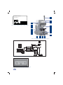 34
34
-
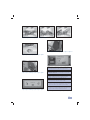 35
35
-
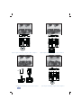 36
36
-
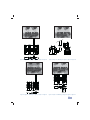 37
37
-
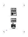 38
38
-
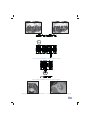 39
39
-
 40
40
-
 41
41
-
 42
42
-
 43
43
-
 44
44
-
 45
45
-
 46
46
-
 47
47
-
 48
48


in altre lingue
- English: JMA DAKAR User manual
- français: JMA DAKAR Manuel utilisateur
- español: JMA DAKAR Manual de usuario
- Deutsch: JMA DAKAR Benutzerhandbuch
- português: JMA DAKAR Manual do usuário
Altri documenti
-
Taurus Alpatec NEW DAKAR 1500 - 2000 - 2500 Manuale del proprietario
-
Sima DAKAR PLUS Manuale del proprietario
-
 Olimpia Splendid control - B0151-B0152 Manuale utente
-
Visonic MCM-140PLUS Manuale del proprietario
-
Güde GMD 400 Istruzioni per l'uso
-
Renishaw HPMA high-precision motorised arm Installation & User's Guide
-
3M DBI-SALA® Sealed-Blok™ Self Retracting Lifeline, Retrieval/Bracket, Cable 3400987, 130 ft. (39m) Istruzioni per l'uso
-
Optoelectronics H15 Manuale utente
-
Festool OFK 700 EQ-Plus Istruzioni per l'uso
-
Vermeiren Trigo T Guida d'installazione
