GYS GYSPOT ALU PRO FV Manuale del proprietario
- Categoria
- Sistema di saldatura
- Tipo
- Manuale del proprietario

73502_V5_06/08/2020
FR
EN
DE
ES
RU
IT
02 / 03-08 / 45-48
02 / 09-14 / 45-48
02 / 15-20 / 45-48
02 / 21-26 / 45-48
02 / 27-32 / 45-48
02 / 33-38 / 45-48
GYSPOT ALU PRO FV
www.gys.fr
NL
02 / 39-44 / 45-48

Notice originale
2
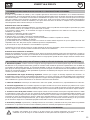
GYSPOT ALU PRO FV
P L 1 2 3 4 5 6 7 8 9 H
V 70 V 75 V 80 V 85 V 90 V 100 V 108 V 118 V 125 V 135 V 150 V
I.
II.
III.
1
2
3
5
6
4

3
GYSPOT ALU PRO FV
FR
Notice originale
AVERTISSEMENTS - RÈGLES DE SÉCURITÉ
CONSIGNE GÉNÉRALE
Ces instructions doivent être lues et bien comprises avant toute opération.
Toute modication ou maintenance non indiquée dans le manuel ne doit pas être entreprise.
Tout dommage corporel ou matériel dû à une utilisation non-conforme aux instructions de ce manuel ne pourra être retenu à la
charge du fabricant.
En cas de problème ou d’incertitude, consulter une personne qualiée pour manier correctement l’installation.
Ces instructions couvrent le matériel dans son état de livraison. Il est de la responsabilité de l’utilisateur de réaliser une analyse des
risques en cas de non-respect de ces instructions.
ENVIRONNEMENT
Ce matériel doit être utilisé uniquement pour faire des opérations de soudage dans les limites indiquées par la plaque signalétique
et/ou le manuel. Il faut respecter les directives relatives à la sécurité. En cas d’utilisation inadéquate ou dangereuse, le fabricant ne
pourra être tenu responsable.
L’installation doit être utilisée dans un local sans poussière, ni acide, ni gaz inammable ou autres substances corrosives. Il en est de
même pour son stockage. S’assurer d’une circulation d’air lors de l’utilisation.
Plages de température :
Utilisation entre -10 et +40°C (+14 et +104°F).
Stockage entre -20 et +55°C (-4 et 131°F).
Humidité de l’air :
Inférieur ou égal à 50% à 40°C (104°F).
Inférieur ou égal à 90% à 20°C (68°F).
Altitude : Jusqu’à 1000 m au-dessus du niveau de la mer (3280 pieds).
PROTECTION INDIVIDUELLE ET DES AUTRES
Le matériel de décharge capacitive peut être dangereux et causer des blessures graves voire mortelles. Elle est destinée à être utilisée
par du personnel qualié ayant reçu une formation adaptée à l’utilisation de la machine (ex : formation carrossier).
Le soudage expose les individus à une source dangereuse de chaleur, d’étincelles, de champs électromagnétiques (attention au
porteur de pacemaker), de risque d’électrocution, de bruit et d’émanations gazeuses.
Pour bien se protéger et protéger les autres, respecter les instructions de sécurité suivantes :
An de se protéger de brûlures et rayonnements, porter des vêtements sans revers, isolants, secs, ignifugés et en
bon état, qui couvrent l’ensemble du corps.
Utiliser des gants qui garantissent l’isolation électrique et thermique.
Utiliser une protection de soudage et/ou une cagoule de soudage d’un niveau de protection sufsant (variable selon
les applications). Protéger les yeux lors des opérations de nettoyage. Les lentilles de contact sont particulièrement
proscrites.
Il est parfois nécessaire de délimiter les zones par des rideaux ignifugés pour protéger la zone des projections et des
déchets incandescents.
Informer les personnes dans la zone de soudage de porter les vêtements adéquats pour se protéger.
Utiliser un casque contre le bruit si le procédé de soudage atteint un niveau de bruit supérieur à la limite autorisée
(de même pour toute personne étant dans la zone de soudage).
Les pièces qui viennent d’être soudées sont chaudes et peuvent provoquer des brûlures lors de leur manipulation.
Il est important de sécuriser la zone de travail avant de la quitter an de protéger les personnes et les biens.
FUMÉES DE SOUDAGE ET GAZ
Les fumées, gaz et poussières émis par le soudage sont dangereux pour la santé. Il faut prévoir une ventilation
sufsante, un apport d’air est parfois nécessaire. Un masque à air frais peut être une solution en cas d’aération
insufsante.
Vérier que l’aspiration est efcace en la contrôlant par rapport aux normes de sécurité.
Attention le soudage dans les environnements réduits nécessite une surveillance à distance de sécurité. Par ailleurs le soudage de
certains matériaux contenant du plomb, cadmium, zinc ou mercure voire du béryllium peuvent être particulièrement nocifs.
Dégraisser également les pièces avant de les souder. Le soudage doit être proscrit à proximité de graisse ou de peinture.

4
GYSPOT ALU PRO FV
FR
Notice originale
RISQUE DE FEU ET D’EXPLOSION
Protéger entièrement la zone de soudage, les matières inammables doivent être éloignées d’au moins 11 mètres.
Un équipement anti-feu doit être présent à proximité des opérations de soudage.
Attention aux projections de matières chaudes ou d’étincelles, car même à travers des ssures, elles peuvent être
source d’incendie ou d’explosion.
Éloigner les personnes, les objets inammables et les containers sous pressions à une distance de sécurité sufsante.
Le soudage dans des containers ou des tubes fermés est à proscrire et dans le cas où ils sont ouverts, il faut les vider de toute matière
inammable ou explosive (huile, carburant, résidus de gaz …).
Les opérations de meulage ne doivent pas être dirigées vers la source de courant de soudage ou vers des matières inammables.
SÉCURITÉ ÉLECTRIQUE
Le réseau électrique utilisé doit impérativement avoir une mise à la terre. Une décharge électrique peut être une
source d’accident grave direct ou indirect, voire mortel.
Ne jamais toucher les parties sous tension à l’intérieur comme à l’extérieur de la source de courant sous-tension (câbles, électrodes,
bras, pistolet,…) car celles-ci sont branchées au circuit de soudage.
Avant d’ouvrir la source de courant de soudage, il faut la déconnecter du réseau et attendre 2 minutes. an que l’ensemble des
condensateurs soit déchargé.
Veiller à changer les câbles, électrodes ou bras, par des personnes qualiées et habilitées, si ceux-ci sont endommagés. Dimension-
ner la section des câbles en fonction de l’application. Toujours utiliser des vêtements secs et en bon état pour s’isoler du circuit de
soudage. Porter des chaussures isolantes, quel que soit le milieu de travail.
CLASSIFICATION CEM DU MATERIEL
Ce matériel de Classe A n’est pas prévu pour être utilisé dans un site résidentiel où le courant électrique est
fourni par le réseau public d’alimentation basse tension. Il peut y avoir des difcultés potentielles pour assurer la
compatibilité électromagnétique dans ces sites, à cause des perturbations conduites, aussi bien que rayonnées à
fréquence radioélectrique.
EN 61000-3-12
Ce matériel est conforme à la CEI 61000-3-12.
EN 61000-3-11
Ce matériel est conforme à la CEI 61000-3-11.
EMISSIONS ELECTRO-MAGNETIQUES
Le courant électrique passant à travers n’importe quel conducteur produit des champs électriques et magnétiques
(EMF) localisés. Le courant de soudage produit un champ électromagnétique autour du circuit de soudage et du
matériel de soudage.
Les champs électromagnétiques EMF peuvent perturber certains implants médicaux, par exemple les stimulateurs cardiaques. Des
mesures de protection doivent être prises pour les personnes portant des implants médicaux. Par exemple, restrictions d’accès pour
les passants ou une évaluation de risque individuelle pour les soudeurs.
Tous les soudeurs doivent utiliser les procédures suivantes an de minimiser l’exposition aux champs électromagnétiques provenant
du circuit de soudage:
• positionner les câbles de soudage ensemble – les xer avec une attache, si possible;
• se positionner (torse et tête) aussi loin que possible du circuit de soudage;
• ne jamais enrouler les câbles de soudage autour du corps;
• ne pas positionner le corps entre les câbles de soudage. Tenir les deux câbles de soudage sur le même côté du corps;
• raccorder le câble de retour à la pièce mise en œuvre aussi proche que possible à la zone à souder;
• ne pas travailler à côté de la source de courant de soudage, ne pas s’assoir dessus ou ne pas s’y adosser ;
• ne pas souder lors du transport de la source de courant de soudage ou le dévidoir.
Les porteurs de stimulateurs cardiaques doivent consulter un médecin avant d’utiliser ce matériel.
L’exposition aux champs électromagnétiques lors du soudage peut avoir d’autres effets sur la santé que l’on ne
connaît pas encore.

Notice originale
5
GYSPOT ALU PRO FV
FR
RECOMMANDATIONS POUR EVALUER LA ZONE ET L’INSTALLATION DE SOUDAGE
Généralités
L’utilisateur est responsable de l’installation et de l’utilisation du matériel de décharge capacitive suivant les instructions du fabricant.
Si des perturbations électromagnétiques sont détectées, il doit être de la responsabilité de l’utilisateur du matériel de décharge
capacitive de résoudre la situation avec l’assistance technique du fabricant. Dans certains cas, cette action corrective peut être aussi
simple qu’une mise à la terre du circuit de soudage. Dans d’autres cas, il peut être nécessaire de construire un écran électromagnétique
autour de la source de courant de soudage et de la pièce entière avec montage de ltres d’entrée. Dans tous les cas, les perturbations
électromagnétiques doivent être réduites jusqu’à ce qu’elles ne soient plus gênantes.
Evaluation de la zone de soudage
Avant d’installer un matériel de décharge capacitive, l’utilisateur doit évaluer les problèmes électromagnétiques potentiels dans la
zone environnante. Ce qui suit doit être pris en compte:
a) la présence au-dessus, au-dessous et à côté du matériel de décharge capacitive d’autres câbles d’alimentation, de commande, de
signalisation et de téléphone;
b) des récepteurs et transmetteurs de radio et télévision;
c) des ordinateurs et autres matériels de commande;
d) du matériel critique de sécurité, par exemple, protection de matériel industriel;
e) la santé des personnes voisines, par exemple, emploi de stimulateurs cardiaques ou d’appareils contre la surdité;
f) du matériel utilisé pour l’étalonnage ou la mesure;
g) l’immunité des autres matériels présents dans l’environnement.
L’utilisateur doit s’assurer que les autres matériels utilisés dans l’environnement sont compatibles. Cela peut exiger des mesures de
protection supplémentaires;
h) l’heure du jour où le soudage ou d’autres activités sont à exécuter.
La dimension de la zone environnante à prendre en compte dépend de la structure du bâtiment et des autres activités qui s’y
déroulent. La zone environnante peut s’étendre au-delà des limites des installations.
Evaluation de l’installation de soudage
Outre l’évaluation de la zone, l’évaluation des installations de matériel de décharge capacitive peut servir à déterminer et résoudre les
cas de perturbations. Il convient que l’évaluation des émissions comprenne des mesures in situ comme cela est spécié à l’Article 10
de la CISPR 11:2009. Les mesures in situ peuvent également permettre de conrmer l’efcacité des mesures d’atténuation.
RECOMMANDATIONS SUR LES METHODES DE REDUCTION DES EMISSIONS ELECTROMAGNETIQUES
a. Réseau public d’alimentation: Il convient de raccorder le matériel de décharge capacitive au réseau public d’alimentation selon
les recommandations du fabricant. Si des interférences se produisent, il peut être nécessaire de prendre des mesures de prévention
supplémentaires telles que le ltrage du réseau public d’alimentation. Il convient d’envisager de blinder le câble d’alimentation dans
un conduit métallique ou équivalent d’un matériel de décharge capacitive installé à demeure. Il convient d’assurer la continuité
électrique du blindage sur toute sa longueur. Il convient de raccorder le blindage à la source de courant de soudage pour assurer un
bon contact électrique entre le conduit et l’enveloppe de la source de courant de soudage.
b. Maintenance du matériel de décharge capacitive : Il convient que le matériel de décharge capacitive soit soumis à l’entretien
de routine suivant les recommandations du fabricant. Il convient que tous les accès, portes de service et capots soient fermés et
correctement verrouillés lorsque le matériel de décharge capacitive est en service. Il convient que le matériel de décharge capacitive
ne soit modié en aucune façon, hormis les modications et réglages mentionnés dans les instructions du fabricant.
c. Câbles de soudage : Il convient que les câbles soient aussi courts que possible, placés l’un près de l’autre à proximité du sol ou
sur le sol.
d. Liaison équipotentielle : Il convient d’envisager la liaison de tous les objets métalliques de la zone environnante. Toutefois,
des objets métalliques reliés à la pièce à souder accroissent le risque pour l’opérateur de chocs électriques s’il touche à la fois ces
éléments métalliques et l’électrode. Il convient d’isoler l’opérateur de tels objets métalliques.
e. Mise à la terre de la pièce à souder : Lorsque la pièce à souder n’est pas reliée à la terre pour la sécurité électrique ou en
raison de ses dimensions et de son emplacement, ce qui est le cas, par exemple, des coques de navire ou des charpentes métalliques
de bâtiments, une connexion raccordant la pièce à la terre peut, dans certains cas, et non systématiquement, réduire les émissions.
Il convient de veiller à éviter la mise à la terre des pièces qui pourrait accroître les risques de blessure pour les utilisateurs ou
endommager d’autres matériels électriques. Si nécessaire, il convient que le raccordement de la pièce à souder à la terre soit
fait directement, mais dans certains pays n’autorisant pas cette connexion directe, il convient que la connexion soit faite avec un
condensateur approprié choisi en fonction des réglementations nationales.
f. Protection et blindage : La protection et le blindage sélectifs d’autres câbles et matériels dans la zone environnante peuvent
limiter les problèmes de perturbation. La protection de toute la zone de soudage peut être envisagée pour des applications spéciales.
TRANSPORT ET TRANSIT DE LA SOURCE DE COURANT DE SOUDAGE
La source de courant de soudage est équipée d’une (de) poignée(s) supérieure(s) permettant le portage / déplacement
à la main. Attention à ne pas sous-évaluer son poids. La (les) poignée(s) n’est (ne sont) pas considérée(s) comme un
moyen d’élingage.
Ne pas utiliser les câbles pour déplacer la source de courant de soudage.
Ne pas faire transiter la source de courant au-dessus de personnes ou d’objets.

Notice originale
6
GYSPOT ALU PRO FV
FR
INSTALLATION DU MATERIEL
• Prévoir une zone sufsante pour aérer la source de courant de soudage et accéder aux commandes.
• Ne pas utiliser dans un environnement comportant des poussières métalliques conductrices.
• Les câbles d’alimentation, de rallonge et de soudage doivent être totalement déroulés an d’éviter toute surchauffe.
Le fabricant n’assume aucune responsabilité concernant les dommages provoqués à des personnes et objets dus à une
utilisation incorrecte et dangereuse de ce matériel.
ENTRETIEN / CONSEILS
• Les utilisateurs de cette machine doivent avoir reçu une formation adaptée à l’utilisation de la machine an de
tirer le maximum de ses performances et de réaliser des travaux conformes (ex : formation de carrossier).
• Vérier que le constructeur autorise le procédé de soudage employé avant toute réparation sur un véhicule.
• La maintenance et la réparation du générateur ne peut être effectuée que par le fabricant. Toute intervention dans ce générateur
effectuée par une tierce personne annulera les conditions de garantie. Le fabricant décline toute responsabilité concernant tout
incident ou accident survenant postérieurement à cette intervention.
• Couper l’alimentation en débranchant la prise, et attendre deux minutes avant de travailler sur le matériel. A l’intérieur, les tensions
et intensités sont élevées et dangereuses.
• Tous les outils de soudage subissent une détérioration lors de leur utilisation. Veiller à ce que ces outils restent propres pour que la
machine donne le maximum de ses possibilités.
• Régulièrement, enlever le capot et dépoussiérer à la soufette. En proter pour faire vérier la tenue des connexions électriques
avec un outil isolé par un personnel qualié.
• Contrôler régulièrement l’état du cordon d’alimentation et du faisceau du circuit de soudage. Si des signes d’endommagement sont
apparents, les remplacer par le fabricant, son service après-vente ou une personne de qualication similaire, an d’éviter tout danger.
• Laisser les ouïes de la source de courant de soudage libres pour l’entrée et la sortie d’air.
ALIMENTATION ÉLECTRIQUE
• Ce matériel est livré avec une prise 16 A de type CEE7/7 et ne doit être utilisé que sur une installation électrique
monophasée 90 V à 240 V (50 - 60 Hz) à trois ls avec un neutre relié à la terre.
• Le courant permanent absorbé (I1p ou ILp) indiqué dans la partie « caractéristiques électriques » de ce manuel
correspond aux conditions d’utilisation maximales. Vérier que l’alimentation et ses protections (fusible et/ou dis-
joncteur) sont compatibles avec le courant nécessaire en utilisation. Dans certains pays, il peut être nécessaire de
changer la prise pour permettre une utilisation aux conditions maximales.
Le segment horizontal au centre de l’afcheur clignote en rouge pour indiquer que l’appareil est alimenté
en veille.
L’appareil se met en protection si la tension d’alimentation est supérieure à 265V. L’appareil empêche la
charge des condensateurs. Pour indiquer ce défaut, les 3 segments horizontaux au centre de l’afcheur
s’allument tant que le défaut est présent.
Charge des condensateurs : le clignotement de l’afcheur indique que le GYSPOT ALU est en train de
charger les condensateurs à la valeur de consigne. En cas de défaut de charge des condensateurs, le
message « DEF » s’afche. Éteindre et rallumer l’appareil. Si le message persiste, veuillez contacter le
service après-vente de la société GYS.
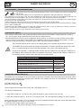
CARACTERISTIQUES ELECTRIQUES
Tension d’alimentation assignée U
1N
1 ~ 90-240 V
Fréquence 50/60 Hz
Tension à vide assignée U
20
/ U
2d
50-200 V
Puissance permanente S
p
0,2 kVA
Courant maximal de court-circuit secondaire I
2cc
7 500 A
Courant permanent secondaire I
2p
110 A

Notice originale
7
GYSPOT ALU PRO FV
FR
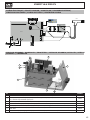
DESCRIPTION DE L’APPAREIL (CF. PAGE 2)
Le débosseleur GYSPOT ALU permet de débosseler les carrosseries en aluminium en soudant des goujons M4 en alumi-
nium par décharge de condensateur. Les condensateurs ont une capacité de 53 millifarads.
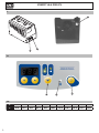
Sortie câble pistolet (Fig. I-
1
)
Sortie câble de masse (Fig. I-
2
)
La face avant de l’appareil a un clavier avec 4 touches et un afcheur à LEDs 7 segments (Fig. II)
L’appareil est équipé d’un pistolet avec un faisceau de 3m.
Les 3 plots servent pour la masse et le maintien central à souder le goujon Ø4
M4 : Alu magnésium (AlMg3) ou Alu silicium (AlSi12)
A l’allumage de l’appareil, un message d’erreur peut apparaitre indiquant que la gâchette est restée appuyée. Il est
possible que le bouton soit bloqué ou qu’il soit en court-circuit.
• Dans le premier cas, débloquer le bouton an qu’il retrouve son état normal.
• Dans le second cas, merci de retourner le produit chez le fabricant.
UTILISATION
Le GYSPOT ALU a été conçu pour effectuer des travaux de réparation des carrosseries en aluminium, qui ont des petites
marques, des rayures ou des impacts de grêle.
Le GYSPOT ALU soude les goujons M4 par décharge de condensateur. Celle-ci se fait dès que l’embout du pistolet est
enfoncé. La soudure est très rapide (2 à 3 millisecondes).
L’appareil peut être programmé en deux modes différents :
- Mode tension : La tension est programmable de 50 à 200 V.
- Mode puissance : La puissance est programmable de L, 1-9, H:
o Le passage d’un mode à l’autre se fait en appuyant sur la touche mode (Fig. II-
4
)
o Tableau de correspondance puissance en fonction de la tension (Cf. Fig. III).
o Appuyer sur le commutateur marche/arrêt situé à droite du clavier (Fig. II-
6
)
o Remarque : la masse rapide est montée d’ofce
o Décaper la zone à redresser, de manière à ce que les 3 plots laiton puissent faire le contact de masse contre la car-
rosserie
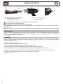
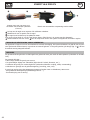
o Positionner le goujon dans le mandrin. Ajuster si besoin la vis de réglage de butée du goujon (voir photos ci-dessous)
o Pour avoir une bonne soudure, la tête du goujon doit dépasser d’un millimètre environ de l’embout (
7
)
o Le réglage de cette position de la tête du goujon se fait en vissant/dévissant l’écrou sur la vis de réglage (
8
)
A la livraison du pistolet, la vis de réglage
10
est desserrée et le curseur
0
est en butée. Ce réglage permet d’exercer
une force d’environ 20 N au moment du déclenchement du tir, ce qui convient pour souder des goujons aluminium M4.
La vis permet de régler la force d’appui du ressort lorsque le tir est déclenché ainsi que de compenser son usure.
Régler la valeur de la tension par l’intermédiaire des touches + et -.
A la mise sous tension la valeur de la puissance par défaut est 5 ce qui correspond à 100 volts.
En général, la valeur pour avoir une bonne soudure d’un goujon de diamètre 4 pour effectuer un débosselage est de 90
V. Ce qui correspond à une puissance de 4.
La valeur de la tension augmente avec l’épaisseur des tôles. Attention, une tension trop élevée peut endommager le
support.
Pour une bonne soudure, seul le « téton » du goujon doit être en contact avec la pièce.
Exercer une légère pression sur le pistolet sans écraser le « téton » du goujon, maintenir le pistolet perpendiculaire à la
tôle. La décharge des condensateurs se fait automatiquement dès que l’embout du pistolet est enfoncé dans la bague.
A cet instant le goujon est soudé. La durée de la soudure est inférieure à 3 millisecondes.
Pour un redressage optimum, nous conseillons de réchauffer la pièce.

Notice originale
8
GYSPOT ALU PRO FV
FR
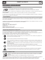
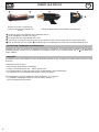
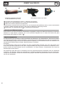
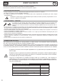
Embout en cuivre à 4 fentes pour
souder les goujons M4 (diamètre Ø
4 mm)
Pistolet à déclenchement automatique sans gâchette
7
La tête du goujon doit dépasser d’un millimètre environ.
8
Vis de réglage de la position du goujon
9
Le goujon doit être perpendiculaire à la tôle.
Ne pas exercer une pression trop forte pour ne pas écraser le téton. Seul le téton est en contact avec la tôle.
10
Une vis moletée avec un curseur
0
permet de régler la compression du ressort lors du déclenchement du tir.
PROTECTION THERMIQUE DU GENERATEUR
L’appareil est muni d’un système de protection thermique automatique. Ce système bloque l’utilisation du générateur
pendant quelques minutes en cas d’utilisation trop intensive. Dans ce cas, le témoin jaune (g. II-
5
) de défaut ther-
mique s’allume.
GARANTIE
La garantie couvre tous défauts ou vices de fabrication pendant 2 ans, à compter de la date d’achat (pièces et main
d’oeuvre).
La garantie ne couvre pas :
• Toutes autres avaries dues au transport.
• L’usure normale des pièces (Ex. : câbles, pinces, etc.).
• Les incidents dus à un mauvais usage (erreur d’alimentation, chute, démontage).
• Les pannes liées à l’environnement (pollution, rouille, poussière).
En cas de panne, retourner l’appareil à votre distributeur, en y joignant :
- un justicatif d’achat daté (ticket de sortie de caisse, facture….)
- une note explicative de la panne.
7 8 9
10
0

9
GYSPOT ALU PRO FV
Translation of the original instructions
STANDARD
GENERAL INSTRUCTIONS
Read and understand the following safety instructions before use.
Any modication or maintenance not specied in the instructions manual should not be undertaken.
The manufacturer is not liable for any injury or damage due to non-compliance with the instructions featured in this manual.
In the event of problems or uncertainties, please consult a qualied person to handle the installation properly.
Make sure to keep the instructions as you might need to refer to them later.
These instructions cover the material in the condition it was delivered. It is the responsibility of the user to carry a risk analysis in
case the instructions are not followed.
ENVIRONMENT
This equipment must only be used for welding operations in accordance with the limits indicated on the descriptive panel and/or in
the user manual. Safety instructions must be followed. In case of improper or unsafe use, the manufacturer cannot be held liable.
This equipment must be used and stored in a room free from dust, acid, ammable gas or any other corrosive agent. The same rules
apply for storage. Operate the machine in an open, or well-ventilated area.
Operating temperature:
Use between -10 and +40°C (+14 and +104°F).
Storage between -20 and +55°C (-4 and 131°F).
Air humidity:
Lower or equal to 50% at 40°C (104°F).
Lower or equal to 90% at 20°C (68°F).
Altitude:
Up to 1000 meters above sea level (3280 feet).
PROTECTION OF THE INDIVIDUALS
Capacitive discharge equipment can be dangerous and cause serious injuries or even death. It needs to be used by a qualied
technician with training relevant to the machine.
Welding exposes the user to dangerous heat, arc rays, electromagnetic elds, risk of electric shock, noise and gas fumes. People
wearing pacemakers are advised to consult a doctor before using the welding machine.
To protect oneself as well as the other, ensure the following safety precautions are taken:
In order to protect you from burns and radiations, wear clothing without turn-up or cuffs. These clothes must be
insulating, dry, reproof, in good condition and cover the whole body.
Wear protective gloves which guarantee electrical and thermal insulation.
Use sufcient welding protective gear for the whole body: hood, gloves, jacket, trousers... (varies depending on the
application/operation). Protect the eyes during cleaning operations. Contact lenses are prohibited during use.
It may be necessary to install reproof welding curtains to protect others against arc rays, weld spatters and sparks. .
Ask people around the working area to look away from at the arc or the molten metal, and to wear protective clothing.
Ensure ear protection is worn by the operator if the work exceeds the authorised noise limit (the same applies to any
person in the welding area).
Parts that have previously been welded will be hot and may cause burns if manipulated.
It is important to secure the working area before leaving to ensure the protection of property and the safety of others.
WELDING FUMES AND GAS
Fumes, gas and dust produced during welding are hazardous to health. It is mandatory to ensure adequate
ventilation and/or extraction to keep fumes and gas away from the work area. Using an air fed welding helmet is
recommended in case of insufcient ventilation in the workplace.
Check that the air supply is effective by referring to the recommended safety regulations.
Precautions must be taken when welding in small areas, and the operator will need supervision from a safe distance. In addition, the
welding of certain materials containing lead, cadmium, zinc, mercury or beryllium may be particularly harmful.
Also remove any grease on the metal pieces before welding. Do not weld in areas where grease or paint are stored.
EN

10
GYSPOT ALU PRO FV
Translation of the original instructions
FIRE AND EXPLOSION RISKS
Protect the entire welding area. Flammable materials must be moved to a minimum safe distance of 11 meters.
A re extinguisher must be readily available near the welding operations.
Keep people, ammable materials/objects and containers that are under pressure at a safe distance.
Welding in closed containers or pipes should be avoided and , if they are opened, they must be emptied of any ammable or explosive
material (oil, fuel, gas ...).
Grinding operations should not be carried out close to the power supply or any ammable materials.
ELECTRICAL SAFETY
The electrical mains used must have an earth terminal. An electric shock could cause serious injuries or potentially
even deadly accidents.
Never make contact with live parts inside or outside the current source (cables, electrodes, arms, guns...) as they are connected to
the welding circuit.
Before opening the device, it is imperative to disconnect it from the mains and wait 2 minutes, so that all the capacitors are dischar-
ged.
Damaged cables and torches must be changed by a qualied and skilled professional. Make sure that the cable cross section is
adequate with the usage (extensions and welding cables). Always wear dry clothes which are in good condition in order to be isola-
ted from the welding circuit. Wear insulating shoes, regardless of the workplace/environment in which you work in.
EMC CLASSIFICATION
This Class A machine is not intended to be used on a residential site where the electric current is supplied by the
domestic low-voltage power grid. There may be potential difculties in ensuring electromagnetic compatibility at
these sites, due to conducted interferences as well as radiation.
EN 61000-3-12
This equipment complies with the IEC 61000-3-12 standard.
EN 61000-3-11
This equipment complies with the IEC 61000-3-11 standard.
ELECTROMAGNETIC INTERFERENCES
The electric currents owing through a conductor cause electrical and magnetic elds (EMF). The welding current
generates an EMF around the welding circuit and the welding equipment.
The EMF electromagnetic elds can interfere with certain medical implants, such as pacemakers. Protection measures must be taken
for people having medical implants. For example, access restrictions for passers-by or an individual risk evaluation for the welders.
Each welder must follow the procedures below in order to minimise exposure to electromagnetic generated by the welding circuit:
• position the welding cables together - strap them if possible;
• keep your head and top half of the body as far from the welding circuit as possible;
• never enrol the cables around your body;
• never position your body between the welding cables. Hold both welding cables on the same side of your body;
• connect the earth clamp as close as possible to the area being welded;
• do not work too close to, do not lean and do not sit on the welding machine
• do not weld when you’re carrying the welding machine or its wire feeder.
People wearing pacemakers are advised to consult their doctor before using this device.
Exposure to electromagnetic elds while welding may have other health effects which are not yet identied.
RECOMMENDATIONS FOR EVALUATING THE WELDING AREA AND INSTALLATION
Miscellaneous
The user is responsible for the correct installation and usage of the welding material based on the instructions supplied by the
manufacturer. If electromagnetic disturbances are detected, it is the user’s responsibility to resolve the situation with the manufacturer’s
technical assistance. In some cases, this corrective action may be as simple as earthing the welding circuit. In other cases, it may be
necessary to construct an electromagnetic shield around the welding power source and around the entire piece by tting input lters.
In all cases, electromagnetic interferences must be reduced until they are no longer inconvenient.
Welding area assessment
Before installing the machine, the user must evaluate the possible electromagnetic problems that may arise in the area where the
installation is planned. The following must be taken into account:
EN

Translation of the original instructions
11
GYSPOT ALU PRO FV
EN
a) the presence (above, below and next to the arc welding machine) of other power cables, remote cables and telephone cables;
b) television transmitters and receivers;
c) computers and other hardware;
d) critical safety equipment such as industrial machine protections;
e) the health and safety of the people in the area such as people with pacemakers or hearing aids;
f) calibration and measuring equipment;
g) the isolation of other pieces of equipment which are in the same area.
The user has to ensure that the devices and pieces of equipment used in the same area are compatible with each other. This may
require extra precautions;
h) the time of day during the welding or other activities have to be performed.
The surface of the area to be considered around the device depends on the building’s structure and other activities that take place
there. The area taken into consideration can be larger than the limits of the installations.
Review of the welding installation
Reviewing the welding installations can be useful to determine and resolve any case of electrical disturbances. The assessment of
emissions must include in situ measurements as specied in Article 10 of CISPR 11: 2009. In situ measurements can also be used to
conrm the effectiveness of mitigation measures.
RECOMMANDATIONS SUR LES METHODES DE REDUCTION DES EMISSIONS ELECTROMAGNETIQUES
a. National power grid: The capacitive discharge equipment must be connected to the national power grid in accordance with the
manufacturer’s recommendation. In case of interferences, it may be necessary to take additional precautions such as the ltering
of the power supply network. Consideration should be given to shielding the power supply cable in a metal conduit or equivalent
of permanently installed capacitive discharge equipment. It is necessary to ensure the electrical continuity of the shielding along
its entire length. The shielding should be connected to the welding current’s source to ensure good electrical contact between the
conduct and the casing of the welding current source.
b. Maintenance of the capacitive discharge equipment: The arc welding machine should be subject to a routine maintenance
check according to the recommendations of the manufacturer. All accesses, service doors and covers should be closed and properly
locked when the capacitive discharge equipment is on. The capacitive discharge equipment must not be modied in any way, except
for the changes and settings outlined in the manufacturer’s instructions.
c. Welding cables: Cables must be as short as possible, close to each other and close to the ground, if not on the ground.
d. Equipotential bonding: consideration should be given to bonding all metal objects in the surrounding area. However, metal
objects connected to the workpiece increase the risk of electric shock if the operator touches both these metal elements and the
electrode. It is necessary to insulate the operator from such metal objects.
e. Earthing of the welded part: When the part is not earthed - due to electrical safety reasons or because of its size and its
location (which is the case with ship hulls or metallic building structures), the earthing of the part can, in some cases but not
systematically, reduce emissions It is preferable to avoid the earthing of parts that could increase the risk of injury to the users or
damage other electrical equipment. If necessary, it is appropriate that the earthing of the part is done directly, but in some countries
that do not allow such a direct connection, it is appropriate that the connection is made with a capacitor selected according to national
regulations.
f. Protection and shielding: The selective protection and shielding of other cables and devices in the area can reduce perturbation
issues. The protection of the entire welding area can be considered for specic situations.
TRANSPORT ET TRANSIT DE LA SOURCE DE COURANT DE SOUDAGE
The welding source is tted with a handle to make it transportable by hand. Be careful not to underestimate the weight
of the machine. The handle are not design to be use to hang the machine to something else.
Do not use the cables or torch to move the machine.
Do not place/carry the unit over people or objects.
EQUIPMENT INSTALLATION
• Provide an adequate area to ventilate the machine and access the controls.
• Do not use in an area with conductive metal dust.
• Power cables, extension leads and welding cables must be fully uncoiled to prevent overheating.
The manufacturer does not accept any liability in relation to damages caused to objects or harm caused to persons
as the result of incorrect and/or dangerous use of the machine .

12
GYSPOT ALU PRO FV
EN
MAINTENANCE / RECOMMENDATIONS
• The operators must have received suitable training in order to use the machine at its maximum potential and
weld correctly.
• Check which welding process is authorised by the manufacturer before attempting any vehicle repair.
• The maintenance and the repair of the . Any work undertaken by a third party on the generator will invalidate the warranty. The
manufacturer will not accept liability in the event of an incident that would occur after this work was undertaken.
• Ensure the machine is unplugged from the mains, and wait for two minutes before carrying out maintenance work. Inside, voltages
and currents are high and dangerous.
• All the welding tools will wear off with use. Ensure that these tools are clean to get the best results.
• Remove regularly the casing and any excess of dust. Take this opportunity to have the electrical connections checked by a qualied
person, with an insulated tool.
• Regularly review the condition of the power cable and welding connection cables. In case of visible signs of damage, organise for
them to be replaced by the manufacturer or a qualied technician.
• Ensure the vents of the device are not blocked to allow adequate air circulation.
ELECTRICITY SUPPLY
• This machine is tted with a 16A socket type CEE7/7 which must be connected to a single-phase 90 V to 240 V
(50 - 60 Hz) power supply tted with three wires and one earthed neutral.
• The absorbed effective current (I1eff) is displayed on the machine, for optimal use. Check that the power supply
and its protection (fuse and/or circuit breaker) are compatible with the current needed by the machine. In some
countries, it may be necessary to change the plug to allow the use at maximum settings.
The horizontal segment at the centre of the display ashes red to indicate that the device is powered.
The GYSPOT ALU protects itself if the voltage exceeds 265V. The device prevents the charge of the capa-
citors. To indicate the failure, the 3 horizontal segments in the centre of the display light up.
Charge of the capacitors: A blinking display indicates that the GYSPOT ALU is charging the capacitors to
the setpoint. ‘DEF’ indicates that there is a capacitors charge fault. Switch off and relight the machine. If
the message persists, please contact after sales service department.
ELECTRICAL SPECIFICATIONS
U
1N
rated power supply voltage 1 ~ 90-240 V
Frequency 50/60 Hz
No load voltage allocated U
20
/ U
2d
50-200 V
Permanent power S
p
0,2 kVA
Maximal current of a secondary short circuit I
2cc
7500 A
Permanent secondary current I
2p
110 A
OPERATING AND SETTING (P.2)
The GYSPOT ALU was designed to carry out repairs to aluminium car bodies, which have minor dings and dents, marks,
scratches or hail damages. Short charging times and thus quick welding sequences are accomplished. The capacitors
have a capacity of 53 milliFarads.
Gun cable output (Fig. I-
1
)
Earth cable output (Fig. I-
2
)
The front panel has a keyboard with 4 keys and a LED display (Fig. II).
This device is equipped with:
- 1 earth cable (Length 3m – Ø 35mm²) with 3 brass terminals for earth contact on the car body.
- 1 pistol with a cable (length 3m - Ø 25 mm ²) to weld Ø 4 studs - M4: Alu magnesium (AlMg3), Alu silicon (AlSi12).
When switching on the product, an error message may come up indicating that the trigger has remain depressed. Either
the trigger has stuck or it may be in short-circuit.
• In the rst case, simply release it and resume use.
• In the second case, the product will require return the manufacturer for service.
Translation of the original instructions

13
GYSPOT ALU PRO FV
EN
OPERATION
The GYSPOT ALU was designed to carry out repairs to aluminium car bodies, which have minor dings and dents, marks,
scratches or hail damages.
Short charging times and thus quick welding sequences are accomplished.
The robust construction ensures high reliability and high power-on time.
The GYSPOT ALU welds M4 studs using capacitor discharge technology. The welding is very fast (2 to 3 milliseconds).
The GYSPOT ALU has 2 operating modes:
- Voltage programming mode: from 50 to 200 Volt.
- Power programming mode: L,1-9,H. L means low, H means high:
o Switching from voltage mode to power mode is done by pressing the ‘mode’ key (Cf. Fig II-
4
). See table Power vs
Voltage (Cf. Fig. III).
o Press the on/off switch on the right of the keyboard (Cf. Fig. II-
6
).
o Notice: the earth adapter is factory mounted
o Grind the area which needs to be straightened, such that the 3 brass pads can make the ground contact with the
aluminium car body.
o Position the stud in the copper tip of the gun. Adjust if necessary the screw adjustment of bumper stud (see pictures
below)
o In order to get a good welding of the stud, the base must come out by approximately 1mm from the extremity of the
mandrel (
7
)
o The position of the stud in the mandrel can be adjusted by screwing / unscrewing the nut on the adjustment screw
(
8
)
Upon delivery of the gun, the screw
10
is loosened and the cursor
0
is in abutment. This setting allows exerting a force
of about 40 N during welding, which is suitable for welding aluminium studs M4. The screw is used to adjust the down
force of the spring when the shot is red or to compensate for the wear of the spring.
Adjust the power or the voltage value using + and - buttons. At power up the power value by default is 5 which is 100
volts. In general, the value to have a good welding of a M4 stud for small dent removal is: voltage = 90 V or power = 4.
Increase the voltage for thicker panels. Be careful, too elevated power can damage the copper base.
For a good weld, only the « nipple of the stud » must be in contact with the component.
Make a small pressure on the gun without crushing the “pin” of the stud. The capacitor discharge is done automatically
when the support comes in the ring.
At this moment the stud is correctly welded. Welding duration is less than 3 milliseconds.
For an optimum repair, we advise you to warm up the metal sheet.
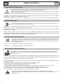
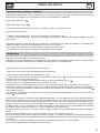
The copper base has 4 slots and is
dedicated to M4 studs
Automatic gun without trigger
7
The base must come out by approximately 1mm from the extremity of the mandrel.
8
Screw for adjusting the stud’s position.
9
The pin must be perpendicular to the sheet.
Do not press too much to not overwrite the nipple. Only the stud is in contact with the sheet.
10
A wheel with index
0
allows adjusting the compression of the spring.
THERMAL PROTECTION
The machine is provided with an automatic thermal protection system, which will stop the machine to prevent it from
overheating. When the Thermal Protection Indicator illuminates (g. II-
5
), let the machine cool down.
7 8 9
10
0
Translation of the original instructions

14
GYSPOT ALU PRO FV
EN
WARRANTY
The warranty covers faulty workmanship for 2 years from the date of purchase (parts and labour).
The warranty does not cover:
• Transit damage.
• Normal wear of parts (eg. : cables, clamps, etc..).
• Damages due to misuse (power supply error, dropping of equipment, disassembling).
• Environment related failures (pollution, rust, dust).
In case of failure, return the unit to your distributor together with:
- The proof of purchase (receipt etc ...)
- A description of the fault reported
Translation of the original instructions

15
GYSPOT ALU PRO FV
Übersetzung der Originalbetriebsanleitung
DE
NORM
ALLGEMEIN
Die Missachtung dieser Anweisungen und Hinweise kann zu schweren Personen- und Sachschäden
führen.
Nehmen Sie keine Wartungarbeiten oder Veränderungen am Gerät vor, die nicht in der Anleitung
gennant werden.
Der Hersteller haftet nicht für Verletzungen oder Schäden, die durch unsachgemäße Handhabung dieses Gerätes entstanden sind.
Bei Problemen oder Fragen zum korrekten Gebrauch dieses Gerätes, wenden Sie sich bitte an entsprechend qualiziertes und ges-
chultes Fachpersonal.
Bewahren Sie diese Bedienungsanleitung zum späteren Nachschlagen auf
Diese Anweisungen beziehen sich auf das Material im Auslieferungszustand. Es liegt in der Verantwortung des Benutzers, bei Nich-
teinhaltung dieser Anweisungen eine Risikoanalyse durchzuführen
UMGEBUNG
Dieses Gerät darf ausschließlich für Schweißarbeiten für die auf dem Siebdruck-Aufdruck bzw. dieser Anleitung angegebenen
Materialanforderungen (Material, Materialstärke, usw) verwendet werden. Beachten Sie die Sicherheitsanweisungen. Der Hersteller
ist nicht für Schäden bei falscher oder gefährlichen Verwendung verantwortlich.
Verwenden Sie das Gerät nicht in Räumen, in denen sich in der Luft größere Mengen metallischer Staubpartikel benden, die
Elektrizität leiten können. Achten Sie sowohl beim Betrieb als auch bei der Lagerung des Gerätes auf eine Umgebung, die frei von
Säuren, Gasen und anderen ätzenden Substanzen ist. Achten Sie auf eine gute Belüftung und ausreichenden Schutz bzw. Ausstattung
der Räumlichkeiten.
Betriebstemperatur:
zwischen -10 und +40°C (+14 und +104°F).
Lagertemperatur zwischen -20 und +55°C (-4 und 131°F).
Luftfeuchtigkeit:
Niedriger oder gleich 50% bis 40°C (104°F).
Niedriger oder gleich 90% bis 20°C (68°F).
Das Gerät ist bis in einer Höhe von 1000m (über NN) einsetzbar.
SICHERHEITSHINWEISE
Kapazitive Entladevorrichtung kann gefährlich sein und zu schweren - unter Umständen auch tödlichen - Verletzungen führen. Das
Gerät ist für den Gebrauch durch qualiziertes Personal geeignet, das eine an den Gebrauch der Maschine angepasste Ausbildung
erhalten hat (z.B. Karosserie-Ausbildung).
Beim Kapazitive Entladevorrichtung ist der Anwender einer Vielzahl potentieller Risiken ausgesetzt: gefährlicher Hitze,
elektromagnetische Störungen (Personen mit Herzschnittmacher oder Hörgerät sollten sich vor Arbeiten in der Nähe der Maschinen
von einem Arzt beraten lassen), elektrische Schläge, Schweißlärm und -rauch.
Schützen Sie daher sich selbst und andere. Beachten Sie unbedingt die folgenden Sicherheitshinweise:
Die Strahlung des Lichtbogens kann zu schweren Augenschäden und Hautverbrennungen führen. Die Haut muss
durch geeignete trockene Schutzbekleidung (Schweißerhandschuhe, Lederschürze, Sicherheitsschuhe) geschützt
werden.
Tragen Sie elektrisch- und wärmeisolierende Handschuhe.
Tragen Sie bitte Schweißschutzkleidung und einen Schweißschutzhelm mit einer genügen Schutzstufe (je nach
Schweißart und -strom). Schützen Sie Ihre Augen bei Reinigungsarbeiten. Kontaktlinsen sind ausdrücklich verboten!
Schirmen Sie den Schweißbereich bei enstprechenden Umgebungsbedingungen durch Schweißvorhänge ab, um
Dritte vor Schweißspritzen, usw. zu schützen.
In der Nähe des Lichtbogens bendliche Personenn müssen ebenfalls auf Gefahren hingewiesen werden und mit den
nötigen Schutzmitteln ausgerüstet werden.
Bei Gebrauch des Kapazitive Entladevorrichtung ensteht sehr großer Lärm, der auf Dauer das Gehör schädigt. Tragen
Sie daher im Dauereinsatz ausreichend Gehörschutz und schützen Sie in der Nähe arbeitende Personen.
ACHTUNG! Das Werkstück ist nach dem Schweißen sehr heiß! Seien Sie daher im Umgang mit dem Werkstück
vorsichtig, um Verbrennungen zu vermeiden.
Der Arbeitsbereich muss zum Schutz von Personen und Geräten vor dem Verlassen gesichert werden.

16
GYSPOT ALU PRO FV
Übersetzung der Originalbetriebsanleitung
DE
SCHWEISSRAUCH/-GAS
Beim Schweißen entstehen Rauchgase bzw. toxische Dämpfen. Sorgen Sie daher immer für ausreichende
Frischluftzufuhr, technische Belüftung oder ein zugelassenes Atemgerät.
Schweißen Sie nur in gut belüfteten Hallen, im Freien oder in geschlossenen Räumen mit ausreichend starker
Absaugung, die den aktuellen Sicherheitsstandards entspricht.
Achtung! Bei Schweißarbeiten in kleinen Räumen müssen Sicherheitsabstände besonders beachtet werden. Beim Schweißen von Blei,
auch in form von Überzügen, verzinkten Teilen, Kadmium, «kadmierte Schrauben», Beryllium (meist als Legierungsbestandteil, z.B.
Beryllium-Kupfer) und andere Metalle entstehen giftige Dämpfe.
Vor dem Schweißen, entfetten Sie die Werkstücke. Schweißarbeiten in unmittelbarer Nähe von Fett und Farben sind grundsätzlich
verboten!
BRAND- UND EXPLOSIONSGEFAHR
Sorgen Sie für ausreichenden Schutz des Schweißbereiches. Der Sicherheitsabstand für Gasaschen (brennbare
Gase) und andere brennbare Materialien beträgt mindestens 11 Meter.
Brandschutzausrüstung muss im Schweißbereich vorhanden sein.Beachten Sie, dass die beim Schweißen
entstehende heiße Schlacke, Spritzer und Funken eine potentielle Quelle für Feuer oder Explosionen darstellen.
Behalten Sie einen Sicherheitsabstand zu Personen, entammbaren Gegenständen und Druckbehältern.
Schweißen Sie keine Behälter mit brennbare Materialien (auch keine Reste davon) -> Gefahr entammbarer Gase. Falls sie geöffnet
sind, müssen entammbares oder explosive Material entfernt werden.
Arbeiten Sie bei Schleifarbeiten immer in entgegengesetzer Richtung zu diesem Gerät und entammbaren Materialen.
ELEKTRISCHE SICHERHEIT
Das Schweißgerät darf nur an einer geerdeten Netzversorgung betrieben werden. Das Berühren stromführender
Teile kann tödliche elektrische Schläge, schwere Verbrennungen bis zum Tod verursachen.
Berühren Sie daher UNTER KEINEN UMSTÄNDEN Teile des Geräteinneren oder das geöffnete Gehäuse wenn das Gerät mit dem
Stromnetz verbunden ist..
Trennen Sie IMMER das Gerät vom Stromnetz und warten Sie 2 weitere Minuten BEVOR Sie das Gerät öffnen, damit sich die Span-
nung der Kondensatoren entladen kann.
Ausschließlich qualiziertem und geschultem Fachpersonal ist es vorbehalten beschädigte Kabel, Elektroden und Zangen auszu-
tauschen. Achten Sie beim Austausch stets darauf das entsprechende Äquivalent zu verwenden. Tragen Sie zur Isolierung beim
Schweißen immer trockene Kleidung in gutem Zustand. Achten Sie unabhängig der Umgebungsbedingungen stets auf isolierendes
Schuhwerk.
CEM-KLASSE DES GERÄTES
Der Norm IEC 60974-10 entsprechend, wird dieses Gerät als Klasse A Gerät eingestuft und ist somit für den
industriellen und/oder professionellen Gebrauch geeignet. Es ist nicht für den Einsatz in Wohngebieten bestimmt,
in denen die lokale Stromversorgung über das öffentliche Niederspannungsnetz geregelt wird. In diesem Umfeld
ist es auf Grund von Hochfrequenz-Störungen und Strahlungen schwierig die elektromagnetische Verträglichkeit
zu gewährleisten.
EN 61000-3-12
Das Gerät entspricht der Norm IEC 61000-3-12.
EN 61000-3-11
Dieses Gerät ist mit der Norm EN 61000-3-11 konform.
ELEKTROMAGNETISCHE FELDER UND STÖRUNGEN
Der durch irgendwelcher Leiter gehender elektrische Strom erzeugt lokalisierte elektrische und magnetische
Felder (EMF). Beim Betrieb von Lichtbogenschweißanlagen kann es zu elektromagnetischen Störungen kommen.
Durch den Betrieb dieses Gerätes können medizinische, informationstechnische und andere Geräte in Ihrer Funktionsweise
beeinträchtigt werden. Personen, die Herzschrittmacher oder Hörgeräte tragen, sollten sich vor Arbeiten in der Nähe der Maschine,
von einem Arzt beraten lassen. Zum Beispiel Zugangseinschränkungen für Passanten oder individuelle Risikobewertung für Schweißer.
Alle Schweißer sollten das folgende Verfahren folgen um die Exposition zu elektromagnetischen Feldern aus der Schaltung zum
Lichtbogenschweißen zu minimieren :
• Elektrodenhalter und Massekabel bündeln, wenn möglich machen Sie sie mit Klebeband fest;
• Achten Sie darauf, dass ihren Oberkörper und Kopf sich so weit wie möglich von der Schweißarbeit benden ;

Übersetzung der Originalbetriebsanleitung
17
GYSPOT ALU PRO FV
DE
• Achten Sie darauf, dass sich die Kabel, den Brenner oder die Masseklemme nicht um Ihren Körper wickeln;
• Stehen Sie niemals zwischen Masse- und Brennerkabel. Die Kabel sollten stets auf einer Seite liegen;
• Verbinden Sie die Massezange mit dem Werkstück möglichst nahe der Schweißzone;
• Arbeiten Sie nicht unmittelbar neben der Schweißstromquelle;
• Während des Transportes der Stromquelle oder des Drahtvorschubkoffer nicht schweißen.
Personen, die Herzschrittmacher oder Hörgeräte tragen, sollten sich vor Arbeiten in der Nähe der Maschine, von
einem Arzt beraten lassen.
Durch den Betrieb dieses Gerätes können medizinische, informationstechnische und andere Geräte in Ihrer
Funktionsweise beeinträchtigt werden.
HINWEIS ZUR PRÜFUNG DES SCHWEISSPLATZES UND DER SCHWEISSANLAGE
Allgemein
Der Anwender ist für die korrekte Einsatz des Kapazitive Entladevorrichtung und des Materials gemäß den Herstellerangaben
verantwortlich. Treten elektromagnetischer Störungen auf, liegt es in der Verantwortung des Anwenders mit Hilfe des Herstellers eine
Lösung zu nden. Die korrekte Erdung des Schweißplatzes inklusive aller Geräte hilft in vielen Fällen. In einigen Fällen kann eine
elektromagnetische Abschirmung des Schweißstroms erforderlich sein.In einigen Fällen kann eine elektromagnetische Abschirmung
des Schweißstroms erforderlich sein. Eine Reduzierung der elektromagnetische Störungen auf ein niedriges Niveau ist auf jeden Fall
erforderlich.
Prüfung des Schweißplatzes
Der Anwender muss potenzielle elektromagnetische Probleme der Umgebung prüfen vor dem Installieren der Kapazitive
Entladevorrichtung. Zur Bewertung potentieller elektromagnetischer Probleme in der Umgebung sollte der Anwender folgendes
berücksichtigen:
a) Netz-, Steuer-, Signal-, und Telekommunikationsleitungen;
b) Radio- und Fernsehgeräte;
c) Computer und andere Steuereinrichtungen;
d) sicherheitskritische Einrichtungen wie Industrieanlagen;
e) die Gesundheit benachbarter Personen, insbesondere wenn diese Herzschrittmacher oder Hörgeräte tragen;
f) Kalibrier- und Messeinrichtungen;
g) die Störfestigkeit anderer Einrichtungen in der Umgebung.
Der Anwender muss die Verfügbarkeit anderer Alternativen prüfen. Weitere Schutzmaßnahmen können erforderlich sein;
h) durch die Tageszeit, zu der die Schweißarbeiten ausgeführt werden müssen.
Die Größe der zu beachtenden Umgebung ist von den örtlichen Strukturen und anderen dort stattndenden Aktivitäten abhängig. Die
Umgebung kann sich über die Grenzen des Schweißplatzes hinaus erstrecken.
Prüfung des Kapazitive Entladevorrichtung
Neben der Überprüfung des Schweißplatzes kann eine Überprüfung des Kapazitive Entladevorrichtung weitere Problem lösen. Die
Prüfung sollte gemäß Art. 10 der IEC/CISPR 11:2009 durchgeführt werden. In-situ Messungen können auch die Wirksamkeit der
Minderungsmaßnahmen bestätigen.
HINWEIS ÜBER DIE METHODEN ZUR REDUZIERUNG ELEKTROMAGNETISCHER FELDER
a. Öffentliche Stromversorgung: Öffentliche Stromversorgung: Das Kapazitive Entladevorrichtung sollte gemäß der Hinweise
des Herstellers an die öffentliche Versorgung angeschlossen werden. Falls Interferenzen auftreten, können weitere Maßnahmen
erforderlich sein (z.B. Netzlter). Eine Abschirmung der Versorgungskabel durch ein Metallrohr kann erforderlich sein.. Kabeltrommeln
sollten vollständig abgerollt werden. Abschirmung von anderen Einrichtungen in der Umgebung oder der gesamten Schweißeinrichtung
können erforderlich sein.
b. Wartung des Gerätes und des Zubehörs: Das Kapazitive Entladevorrichtung muss gemäß der Hinweise des Herstellers an
die öffentliche Versorgung angeschlossen werden. Alle Klappen und Deckel am Gerät müssen im Betrieb geschlossen sein. Das
Schweißgerät und das Zubehör dürfen nur den Anweisungen des Geräteherstellers gemäß verändert werden.
c. Schweißkabel : Schweißkabel sollten so kurz wie möglich sein und gebündelt am Boden verlaufen.
d. Potenzialausgleich: Alle metallischen Teile des Schweißplatzes müssen in den Potentialausgleich einbezogen werden. Bei
gleichzeitiger Berührung des Brennersspitze und metallischer Teile besteht die Gefahr eines elektrischen Schlags. Der Anwender
muss sich von metallischen Bestückungen isolieren.
e. Erdung des Werkstücks: Die Erdung des Werkstücks kann in bestimmte Fälle die Störung reduzieren. Erden Sie keine
Werkstücken, wenn dadurch ein Verletzungsrisiko für den Benutzer oder die Gefahr der Beschädigung anderer elektrischer Geräte
entsteht. Die Erdung kann direkt oder über einen Kondensator erfolgen. Der Kondensator sollte gemäß der nationalen Normen
gewählt werden.
f. Schutz und Trennung: Der Schutz und die selektive Abschirmung andere Leitungen und Geräte in der Umgebung können
Interferenzprobleme reduzieren. Die Abschirmung der gesamten Schweißzone kann bei speziellen Anwendungen nötig sein.

18
GYSPOT ALU PRO FV
DE
TRANSPORT DER SCHWEISSSTROMQUELLE
Das Schweißgerät lässt sich mit dem Tragegurt auf der Geräteoberseite bequem heben. Unterschätzen Sie jedoch nicht
dessen Eigengewicht! Der Handgriff ist jedoch kein Lastaufnahmemittel.
Ziehen Sie niemals an Kabeln, um das Gerät zu bewegen.
Das Gerät darf nicht über Personen oder Objekte hinweg gehoben werden.
AUFSTELLUNG
• Achten Sie auf eine gute Belüftung und ausreichend Schutz bzw. Ausstattung der Räumlichkeiten. Der Netzstecker muss zu jeder
Zeit frei zugänglich sein.
• Verwenden Sie das Gerät nicht in einer elektromagnetisch sensiblen Umgebung.
• Die Versogung-, Verlängerung- und Schwießkabel müssen komplett abgerollt werden um Überhitzerisiko zu verhindern.
Der Hersteller GYS haftet nicht für Verletzungen oder Schäden, die durch unsachgemäße Handhabung dieses
Gerätes entstanden sind.
WARTUNG / HINWEISE
• Die Benutzer des Gerätes müssen für den Gebrauch unterwiesen werden, um alle Einstellungen abrufen zu
können, die das Gerät bietet, und um alle Anwendungen sachkonform durchzuführen (z.B.: Karosseriebau).
• Vor jeder Fahrzeugreparatur ist zu überprüfen, ob der Schweißprozess vom Hersteller genehmigt ist.
• Die Wartung und Reparatur des Generators darf nur vom Hersteller durchgeführt werden. Jeder Eingriff in den Generator durch
einen Dritten führt zur Ungültigkeit der Garantiebedingungen. Der Hersteller lehnt jegliche Haftung ab, die durch Störfälle oder
Pannen nach dem Eingriff entstehen.
• Stromversorgung durch Herausziehen des Steckers unterbrechen und zwei Minuten warten, bevor an dem Gerät gearbeitet wird.
Die Spannungen und Ströme im Gerät sind hochgefährlich.
• Durch die Benutzung unterliegen alle Schweißwerkzeuge einem Verschleiß. Auf saubere Werkzeuge ist zu achten, damit das Gerät
seine maximalen Leistungen erreichen kann.
• Nehmen Sie regelmäßig (mindestens 2 bis 3 Mal im Jahr) das Gehäuse ab und reinigen Sie das Innere des Gerätes mit Pressluft.
Lassen Sie das Gerät regelmäßig von einem qualizierten Techniker auf die elektrische Betriebssicherheit prüfen.
• Überprüfen Sie regelmäßig den Zustand des Netzkabels und des Kabelstrangs des Schweißstromkreises. Sollten Zeichen von
Beschädigungen sichtbar sein, sind sie auszutauschen, durch den Hersteller, seinen Kundendienst oder eine Person mit ähnlicher
Qualikation, um jegliches Risiko zu vermeiden.
• Lüftungsschlitze nicht bedecken.
STROMVERSORGUNG
• Die Geräte besitzen einen Schutzkontaktsstecker (Schukostecker) (EEC7/7) und müssen an eine einphasige, geer-
dete 90-240 V/16A (50-60Hz) Schutzkontaktsteckdose angeschlossen werden.
• Die Stromaufnahme (I1eff) bei maximaler Leistung ist auf dem Typenschild der Maschine angegeben. Bitte prüfen
Sie, ob die Stromversorgung und die Absicherung mit dem Strom, den Sie benötigen, übereinstimmen. In Ländern
mit abweichender Netzversorgungswerten kann ein Tausch des Netzsteckers erforderlich sein, um die maximale
Leistung abrufen zu können.
Das horizontal ausgerichtete Segment in der Mitte des Displays auf dem Bedienfeld blinkt rot auf, wenn
sich das Gerät im Stand-By-Modus bendet.
Das Gerät verfügt über einen Überspannungsschutz gegen Überschreitung der Anschlussspannungswertes
über 265V. In diesem Fall leuchten die 3 horizontal ausgerichteten LEDs in der Mitte des Displays auf.
Kondensatorentladung: Ein blinkendes Display zeigt an, dass das GYSPOT ALU die Kondensatoren bis zu
ihrem Sollwert wiederauädt. Die Anzeige „DEF“ bedeutet, dass ein Kondensatorenfehler vorliegt. Schal-
ten Sie in diesem Fall das Gerät aus und starten Sie das System erneut. Sollte die Anzeige auch weiterhin
aueuchten, kontaktieren Sie bitte den Fachservice Ihres Händlers.
ELEKTRISCHE DATEN
Nennspannung. U
1N
1 ~ 90-240 V
Frequenz 50/60 Hz
Leerlaufspannung U
20
/ U
2d
50-200 V
Dauerleistung S
p
0,2 kVA
Maximaler sekundärer Kurzschlussstrom I
2cc
7 500 A
Sekundäre Dauerstrom I
2p
110 A
Übersetzung der Originalbetriebsanleitung

19
GYSPOT ALU PRO FV
DE
ANWENDUNG (S. 2)
Das Ausbeulspotter GYSPOT ALU ermöglicht durch Kondensatorenentladung und in Zusammenhang mit M4 Aluminium-
schweißbolzen Ausbeularbeiten an Aluminiumkarosserien vorzunehmen.
Die Kondensatoren haben eine Kapazität von 53 mF.
Ausgang Pistolenkabel (Abb. I-
1
)
Ausgang Massekabel (Abb. I-
2
)
Auf der Frontseite des Gerätes bendet sich ein Bedienfeld mit 4 Drucktasten und eine 3-stellige 7-Segment LED-
Anzeige (Abb. II).
Das Gerät wird geliefert mit:
- 1 Massekabel (Länge 3m – Ø 35 mm²) mit 3 Kontaktstifte.
- 1 Schweißpistole und passendes Kabel (Länge: 3m – Ø 25mm²) zum Verschweißen von Ø 4mm M4 Schweißbolzen:
Alu-Magnesium (AlMg3) oder Alu-Silizium (AlSi12).
Beim Einschalten des Gerätes erscheint die Fehlermeldung, dass der Brennertaster aktiv ist: Der Taster ist blockiert oder
kurzgeschlossen.
• Ist der Taster blockiert, entriegeln Sie ihn.
• Bei defektem Taster, schicken Sie das Gerät zur Reparatur an den Hersteller bzw. der Serviceabteilung Ihres Fa-
chhändlers.
VERWENDUNG
Der GYSPOT ALU wurde konzipiert, um an Aluminiumkarosserien Reparaturen von kleinen. Dellen, Kratzern oder Ha-
gelschäden ausführen zu können.
GYSPOT ALU verschweißt M4 Stifte durch Kondensatorentladung. Der Schweißprozess wird durch Erreichen eines jus-
tierbaren Druckpunktes automatisch ausgelöst. Das Anschweißen erfolgt sehr schnell (2 bis 3ms).
Das Gerät verfügt über 2 Einstellmodi:
- Modus Spannung: Spannungseinstellung zwischen 50V und 200V.
- Modus Leistung: Leistungseinstellung von L-1 bis 9-H: L = Low (Niedrig), H = High (Hoch).
o Wechsel zwischen Spannungs- und Leistungsmodus durch Drücken der ‚Modus’ Taster (s. Abb. II-
4
, S.2). Tabelle:
Leistungsstufe in Abhängigkeit der Spannungswerte (s. Abb. III, S.2).
o Drücken Sie den AN/ AUS Schalter auf der rechten Seite des Gerätes (s. Abb. II-
6
, S.2).
o Bemerkung: Die Aufsteckmasse ist werkseitig montiert.
o Entfernen Sie die Lackschicht an der Stelle, an der Sie das Blech ausbeulen möchten.
o Stecken Sie den Schweißbolzen in die Aufnahme der Pistolenspitze und xieren Sie ihn (s. nachfolgende Abbildung)
o Um ein gutes Schweißergebnis zu erzielen, sollte der Flansch des Schweißbolzens einen ca. 1 Millimeter Spalt zur
Aufnahme haben (
7
auf der nachfolgenden Abbildung)
o Fixieren Sie diese Einstellung, indem Sie sie mittels der Mutter kontern (
8
auf der nachfolgenden Abbildung)
Die Vorspannung der Auslösung
10
im Pistoleninneren ist werkseitig auf ca. 20N voreingestellt und kann mit der Rändel-
mutter
0
justiert werden. Darüber hinaus dient die Schraube dazu dem Pistolenrückstoß auszugleichen.
Stellen Sie die Spannung mit Hilfe der + und - Tasten ein. Beim Einschalten des Gerätes ist der Leistungswert 5
voreingestellt, was einer Spannung von 100V entspricht. Allgemein wird, um einen Ø 4mm² Schweißbolzen für die
Reparatur einer kleineren Delle anzuschweißen, eine Spannung von 90V benötigt. Dies entspricht der Leistungsstufe 4.
Der Spannungswert erhöht sich mit zunehmender Dicke des Werkstückes. ACHTUNG! Eine zu hohe Spannung kann die
Bolzenaufnahme beschädigen.
Um ein gutes Schweißergebnis zu erzielen, achten Sie darauf, dass lediglich die Spitze des Bolzens mit dem Werkstück
in Berührung kommt.
Üben Sie einen leichten Druck auf die Pistole aus ohne die Spitze des Schweißbolzens zu zerstören und halten Sie die
Pistole senkrecht zum Werkstück. Die Kondensatorenentladung erfolgt automatisch bei Erreichen der eingestellten
Vorspannung.
Der Schweißbolzen ist nun am Werkstück angeschweißt. Der Schweißvorgang dauert weniger als 3 Millisekunden.
Um den Bolzen optimal an das Werkstück anzuschweißen, wird empfohlen das Werkstück vor dem Anschweißvorgang
frisch zu überschleifen und anzuwärmen.
Übersetzung der Originalbetriebsanleitung

20
GYSPOT ALU PRO FV
DE
4-schlitzige Kupferbolzenaufnahme
für M4 Schweißbolzen (Ø 4 mm)
Automatische Pistole ohne Taster
7
Der Flansch des Schweißbolzens sollte ca. 1 Millimeter hervorstehen.
8
Schraube zur Positionsanpassung und –Fixierung des Schweißbolzens
9
Halten Sie die Pistole senkrecht zum Werkstück.
Üben Sie keinen zu starken Druck auf die Pistole aus, um die Spitze des Schweißbolzens nicht zu stark in das Werkstück
zu drücken. Lediglich die Spitze des Bolzens sollte mit dem Werkstück in Berührung kommen.
10
Rändelmutter und Gewindeschraube
0
zur Einstellung des Federdrucks.
THERMISCHER ÜBERLASTSCHUTZ
Dieses Gerät ist mit einem thermischen Überlastschutz ausgestattet, welches den Betrieb des Gerätes bei intensivem
Gebrauch für einige Minuten unterbricht, bis es sich ausreichend abgekühlt hat. In diesem Fall leuchtet die gelbe
Kontrollanzeige des Gerätes auf (Abb. II-
5
).
HERSTELLERGARANTIE
Die Garantieleistung des Herstellers erfolgt ausschließlich bei Fabrikations- oder Materialfehlern, die binnen 24 Monate
nach Kauf angezeigt werden (nachweis Kaufbeleg). Nach Anerkenntnis des Garantieanspruchs durch den Hersteller bzw.
seines Beauftragten erfolgen eine für den Käufer kostenlose Reparatur und ein kostenloser Ersatz von Ersatzteilen. Die
Garantiezeitraum bleibt aufgrund erfolgter Garantieleistungen unverändert.
Ausschluss:
Die Garantieleistung erfolgt nicht bei Defekten, die durch unsachgemäßen Gebruach, Sturz oder harte Stöße sowie
durch nicht autorisierte Reparaturen oder durch Transportschäden, die infolge des Einsendens zur Reparatur, hervor-
gerufen worden sind. Keine Garantie wird für Verschleißteile (z. B. Kabel, Klemmen, Vorsatzscheiben usw.) sowie bei
Gebruachsspuren übernommen.
Das betreffende Gerät bitte immer mit Kaufbeleg und kurzer Fehlerbeschreibung ausschließlich über den Fachhandel
einschicken. Die Reparatur erfolgt erst nach Erhalt einer schriftlichen Akzeptanz (unterschrift) des zuvor Kostenvoran-
schlags durch den Besteller. Im Fall einer Garantieleistung trägt der Hersteller ausschließlich die Kosten für den Rückver-
sand an den Fachhändler.
7 8 9
10
0
Übersetzung der Originalbetriebsanleitung
La pagina si sta caricando...
La pagina si sta caricando...
La pagina si sta caricando...
La pagina si sta caricando...
La pagina si sta caricando...
La pagina si sta caricando...
La pagina si sta caricando...
La pagina si sta caricando...
La pagina si sta caricando...
La pagina si sta caricando...
La pagina si sta caricando...
La pagina si sta caricando...
La pagina si sta caricando...
La pagina si sta caricando...
La pagina si sta caricando...
La pagina si sta caricando...
La pagina si sta caricando...
La pagina si sta caricando...
La pagina si sta caricando...
La pagina si sta caricando...
La pagina si sta caricando...
La pagina si sta caricando...
La pagina si sta caricando...
La pagina si sta caricando...
La pagina si sta caricando...
La pagina si sta caricando...
La pagina si sta caricando...
La pagina si sta caricando...
-
 1
1
-
 2
2
-
 3
3
-
 4
4
-
 5
5
-
 6
6
-
 7
7
-
 8
8
-
 9
9
-
 10
10
-
 11
11
-
 12
12
-
 13
13
-
 14
14
-
 15
15
-
 16
16
-
 17
17
-
 18
18
-
 19
19
-
 20
20
-
 21
21
-
 22
22
-
 23
23
-
 24
24
-
 25
25
-
 26
26
-
 27
27
-
 28
28
-
 29
29
-
 30
30
-
 31
31
-
 32
32
-
 33
33
-
 34
34
-
 35
35
-
 36
36
-
 37
37
-
 38
38
-
 39
39
-
 40
40
-
 41
41
-
 42
42
-
 43
43
-
 44
44
-
 45
45
-
 46
46
-
 47
47
-
 48
48


GYS GYSPOT ALU PRO FV Manuale del proprietario
- Categoria
- Sistema di saldatura
- Tipo
- Manuale del proprietario
in altre lingue
- français: GYS GYSPOT ALU PRO FV Le manuel du propriétaire
- español: GYS GYSPOT ALU PRO FV El manual del propietario
- Deutsch: GYS GYSPOT ALU PRO FV Bedienungsanleitung
- Nederlands: GYS GYSPOT ALU PRO FV de handleiding
Documenti correlati
-
GYS GYSPOT COMBI 230.E PRO Manuale del proprietario
-
GYS GYSPOT EXPERT 200 Manuale del proprietario
-
-
-
GYS GYSPOT ALU PRO FV Scheda dati
-
GYS GYSPOT PTI GENIUS - 220 V Manuale del proprietario
-
-
GYS GYSPOT PTI GENIUS - 220 V Manuale del proprietario
-
GYS M1 GYS AUTO Manuale del proprietario
-