Cebora POWER SPOT 5700 Manuale utente
- Categoria
- Sistema di saldatura
- Tipo
- Manuale utente

19/12/2019
3.300.103/C
IT MANUALE DI ISTRUZIONI PER SALDATRICE A
SCARICA DI CONDENSATORI pag. 2
EN INSTRUCTION MANUAL FOR capacitor discarge
WELDING MACHINE page 9
DE BETRIEBSANLEITUNG FÜR KONDENSATOR-STOSSENTLADUNG
SSCHWEISSMASCHINE Seite 16
FR MANUEL D'INSTRUCTIONS POUR POSTE A SOUDER
A DECHARGE DE CONDENSATEURS page 24
ES MANUAL DE INSTRUCCIONES PARA SOLDADORA
DE DESCARGA DE CONDENSADORES pag. 32
NL INSTRUCTIEHANDLEIDING VOOR LASAPPARAAT MET
CONDENSATORONTLADING pag. 40
Parti di ricambio e schemi elettrici / vedi Allegato
Spare parts and wiring diagrams / see Annex
Schaltpläne und Ersatzteilliste / Siehe Anlage
Schémas électriques et liste des pièces de rechange / Cf. Annexe
Esquemas eléctricos & lista recambios / Ver Anexo
Esquemas elétricos e lista de peças sobresselentes / Veja Anexo
Sähkökaaviot & varaosaluettelo / Ks.Liite
El-diagrammer & liste over reservedele / Se Bilag
Elektrische Schema’s En Lijst Van Reserveonderdelen / Zie bijlage
Elscheman och reservdelslista / Se Bilaga
ΗΛΕΚΤΡΙΚΑ ΔΙΑΓΡΑΜΜΑΤΑ & ΚΑΤΑΛΟΓΟΣ ΑΝΤΑΛΛΑΚΤΙΚΩΝ /Βλέπε ΠΑΡΑΡΤΗΜΑ

2
MANUALE DI ISTRUZIONI PER SALDATRICE A SCARICA DI CONDENSATORI
IMPORTANTE: PRIMA DELLA MESSA IN OPERA
DELL'APPARECCHIO LEGGERE IL CONTENUTO DI QUE-
STO MANUALE E CONSERVARLO, PER TUTTA LA VITA
OPERATIVA, IN UN LUOGO NOTO AGLI INTERESSATI.
QUESTO APPARECCHIO DEVE ESSERE UTILIZZATO
ESCLUSIVAMENTE PER OPERAZIONI DI SALDATURA.
1 PRECAUZIONI DI SICUREZZA
LA SALDATURA ED IL TAGLIO AD ARCO POSSO-
NO ESSERE NOCIVI PER VOI E PER GLI ALTRI,
pertanto l'utilizzatore deve essere istruito contro i rischi, di
seguito riassunti, derivanti dalle operazioni di saldatura. Per
informazioni più dettagliate richiedere il manuale
cod.3.300758
RUMORE
Questo apparecchio non produce di per se rumo-
ri eccedenti gli 80dB. Il procedimento di taglio
plasma/saldatura può produrre livelli di rumore
superiori a tale limite; pertanto, gli utilizzatori dovranno
mettere in atto le precauzioni previste dalla legge.
CAMPI ELETTROMAGNETICI- Possono essere dannosi.
· La corrente elettrica che attraversa qualsi-
asi conduttore produce dei campi elettro-
magnetici (EMF). La corrente di saldatura o
di taglio genera campi elettromagnetici at-
torno ai cavi e ai generatori.
· I campi magnetici derivanti da correnti elevate possono
incidere sul funzionamento di pacemaker. Ai portatori di
pace maker è proibito usare la macchina o avvicinarsi
ai cavi.
· L’ esposizione ai campi elettromagnetici della salda-
tura o del taglio potrebbe avere effetti sconosciuti sulla
salute. Ogni operatore, per ridurre i rischi derivanti dall’
esposizione ai campi elettromagnetici, deve attenersi alle
seguenti procedure:
- Fare in modo che il cavo di massa e della pinza porta-
elettrodo o della torcia rimangano afancati. Se possi-
bile, ssarli assieme con del nastro.
- Non avvolgere i cavi di massa e della pinza porta elet-
trodo o della torcia attorno al corpo.
- Non stare mai tra il cavo di massa e quello della pin-
za portaelettrodo o della torcia. Se il cavo di massa
si trova sulla destra dell’operatore anche quello della
pinza portaelettrodo o della torcia deve stare da quella
parte.
- Collegare il cavo di massa al pezzo in lavorazione più
vicino possibile alla zona di saldatura o di taglio.
- Non lavorare vicino al generatore.
ESPLOSIONI
· Non saldare in prossimità di recipienti a pressione
o in presenza di polveri, gas o vapori esplosivi.
· Maneggiare con cura le bombole ed i regolatori di
pressione utilizzati nelle operazioni di saldatura.
COMPATIBILITÀ ELETTROMAGNETICA
Questo apparecchio è costruito in conformità alle indicazio-
ni contenute nella norma IEC 60974-10(Cl. A) e deve essere
usato solo a scopo professionale in un ambiente industriale.
Vi possono essere, infatti, potenziali difcoltà nell'assicurare
la compatibilità elettromagnetica in un ambiente diverso da
quello industriale.
SMALTIMENTO APPARECCHIATURE ELETTRICHE
ED ELETTRONICHE
Non smaltire le apparecchiature elettriche assieme ai
riuti normali!
In ottemperanza alla Direttiva Europea 2002/96/CE sui riuti
da apparecchiature elettriche ed elettroniche e relativa at-
tuazione nell'ambito della legislazione nazionale, le apparec-
chiature elettriche giunte a ne vita devono essere raccolte
separatamente e conferite ad un impianto di riciclo ecocom-
patibile. In qualità di proprietario delle apparecchiature dovrà
informarsi presso il nostro rappresentante in loco sui sistemi
di raccolta approvati. Dando applicazione a questa Diretti-
va Europea migliorerà la situazione ambientale e la salute
umana!
IN CASO DI CATTIVO FUNZIONAMENTO RICHIEDETE
L’ASSISTENZA DI PERSONALE QUALIFICATO.
Precauzioni particolari debbono essere prese nel caso di
impiego in posizioni sopraelevate.
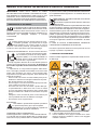
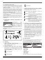
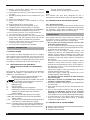
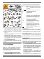
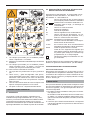
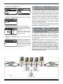
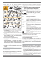
1.1 TARGA DELLE AVVERTENZE
Il testo numerato seguente corrisponde alle caselle numera-
te della targa.
B. I rullini trainalo possono ferire le mani.
C. Il lo di saldatura ed il gruppo trainalo sono sotto
tensione durante la saldatura. Tenere mani eoggetti
metallici a distanza.

3
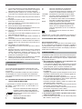
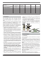
1. Le scosse elettriche provocate dall’elettrodo di sal-
datura o dal cavo possono essere letali. Proteggersi
adeguatamente dal pericolo di scosse elettriche.
1.1 Indossare guanti isolanti. Non toccare l’elettrodo a
mani nude. Non indossare guanti umidi o danneggia-
ti.
1.2 Assicurarsi di essere isolati dal pezzo da saldare e
dal suolo
1.3 Scollegare la spina del cavo di alimentazione prima
di lavorare sulla macchina.
2. Inalare le esalazioni prodotte dalla saldatura può es-
sere nocivo alla salute.
2.1 Tenere la testa lontana dalle esalazioni.
2.2 Utilizzare un impianto di ventilazione forzata o di sca-
rico locale per eliminare le esalazioni.
2.3 Utilizzare una ventola di aspirazione per eliminare le
esalazioni.
3. Le scintille provocate dalla saldatura possono cau-
sare esplosioni od incendi.
3.1 Tenere i materiali inammabili lontano dall’area di
saldatura.
3.2 Le scintille provocate dalla saldatura possono cau-
sare incendi Tenere un estintore nelle immediate vi-
cinanze e far sì che una persona resti pronta ad uti-
lizzarlo.
3.3 Non saldare mai contenitori chiusi.
4. I raggi dell’arco possono bruciare gli occhi e ustiona-
re la pelle.
4.1 Indossare elmetto e occhiali di sicurezza. Utilizzare
adeguate protezioni per le orecchie e camici con il
colletto abbottonato. Utilizzare maschere a casco
con ltri della corretta gradazione. Indossare una
protezione completa per il corpo.
5. Leggere le istruzioni prima di utilizzare la macchina
od eseguire qualsiasi operazione su di essa.
6. Non rimuovere né coprire le etichette di avvertenza
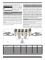
2 DESCRIZIONI GENERALI
2.1 SPECIFICHE
La macchina è stata progettata e realizzata per la sal-
datura di prigionieri lettati Ø 3, 4, 5, 6 e 8 mm, ferrosi e
non ferrosi.
Questo sistema di saldatura utilizza la scarica estrema-
mente rapida (2-3 ms) di una batteria di condensatori
che consente la saldatura di prigionieri lettati con punta
di innesco.
2.2 SPIEGAZIONE DEI DATI TECNICI RIPORTATI
SULLA TARGA DI MACCHINA
L’ apparecchio è costruito secondo le seguenti norme:
IEC 60974-1 / IEC 60974-10 (CL. A) / IEC 61000-3-11 /
IEC 61000-3-12.
N° Numero di matricola da citare sempre per
qualsiasi richiesta relativa alla saldatrice.
1
~
Trasformatore monofase-raddrizzatore con
dispositivo per la carica e la scarica di
condensatori.
U0 Tensione a vuoto secondaria.
E Energia di saldatura.
C Valore della capacità.
Uc Tensione regolabile sui condensatori.
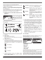
U1 Tensione nominale di alimentazione.
La macchina è prevista per le tensioni 115V
e 230V con cambio tensione automatico.
1-50/60Hz Alimentazione monofase 50 oppure 60Hz.
I1max Corrente massima assorbita alla corrispon-
dente tensione di alimentazione.
I1eff E' il massimo valore della corrente effettiva
assorbita considerando il fattore di servizio.
IP23S Grado di protezione della carcassa.
Grado 3 come seconda cifra signica che
questo apparecchio può essere immagaz-
zinato, ma non impiegato all’esterno du-
rante le precipitazioni, se non in condizione
protetta.
S
Idonea a lavorare in ambienti con rischio
accresciuto.
NOTA:
L’apparecchio è inoltre stato progettato per lavorare in
ambienti con grado di inquinamento 3. (Vedi IEC 60664).
2.3 DESCRIZIONE DELLE PROTEZIONI
2.3.1 Protezione termica
Questo apparecchio è protetto da un termostato il qua-
le, se si superano le temperature ammesse, impedisce
il funzionamento della macchina. In queste condizioni il
ventilatore continua a funzionare ed il display indicherà il
codice di errore "Warning 8".
3 INSTALLAZIONE
L'installazione della macchina deve essere fatta da perso-
nale esperto. Tutti i collegamenti debbono essere eseguiti
in conformità alle norme vigenti e nel pieno rispetto della
legge antinfortunistica.
1 Non posizionare la saldatrice su un pavimento con
una inclinazione maggiore di 10°
La circolazione dell'aria deve essere libera in entrata
e in uscita e la saldatrice deve essere protetta dall'in-
gresso di liquidi, sporco, limature metalliche ecc.
2 Controllare che la tensione di alimentazione corrispon-
da alla tensione indicata sulla targa dei dati tecnici del-
la saldatrice.
Collegare una spina di portata adeguata al cavo di ali-
mentazione assicurandosi che il conduttore giallo/ver-
de sia collegato allo spinotto di terra.
La portata dell'interruttore magnetotermico o dei fusi-
bili, in serie alla alimentazione, deve essere uguale alla
corrente I1 assorbita dalla macchina.
Eventuali prolunghe debbono essere di sezione ade-
guata alla corrente I1 assorbita.
Se l' alimentazione è 115V, la macchina può funzionare
per tensioni comprese tra 96V e 140V.
Se l' alimentazione è 230V, la macchina può funzionare
per tensioni comprese tra 190V e 260V.
Il cambio di alimentazione deve essere eseguito a
macchina spenta.
3 Ai portatori di pace maker è proibito usare la mac-
china o avvicinarsi ai cavi.
4 Inserire a fondo la spina del cavo di massa nella presa
B e ruotare in senso orario.

4
5 Inserire a fondo la spina della pistola nella presa C e
ruotare in senso orario.
6 Accendere la saldatrice con l'interruttore E. (l'accen-
sione e lo spegnimento non vanno ripetuti con fre-
quenza perché la dissipazione dell'energia contenuta
nei condensatori può causare riscaldamento e danni).
7 Per limitare l'esposizione al campo magnetico tenere il
cavo della pistola dal lato della mano che la impugna,
evitando di avvolgersi con il cavo.
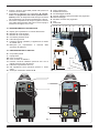
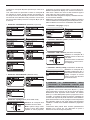
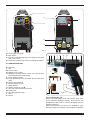
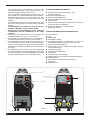
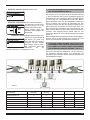
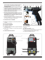
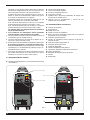
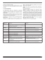
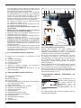
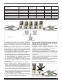
3.1 DESCRIZIONE DELL'APPARECCHIO
A- Display per impostazione e controllo dell'inverter
B- Morsetto di uscita positivo
C- Morsetto di uscita negativo
D- Connettore pulsante torcia
E- Interruttore generale
F- Fusibile Ø 6,3x32 (ritardato). L'apparecchio è dotato
di fusibile 12A-T.
G- Manopola per impostazione e controllo delle
operazioni di saldatura.
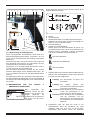
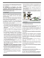
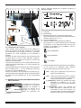
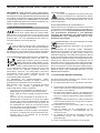
3.2 DESCRIZIONE DELLA PISTOLA
K- Corpo della pistola
L- Impugnatura
M- Cavo di comando
N- Cavo corrente di saldatura
O- Pulsante comando saldatura (funziona solo con la
pistola premuta contro la lamiera)
P- Indicatore impostazione di forza
Q- Vite regolazione forza (aumenta girando in senso
orario)
R- Anello per sostenere il distanziale Z
A
B C
G
D
E
F
Fig. 1
S- Ghiera pressacavo
T- Sof etti di sicurezza
U- Viti di ssaggio anello R
V- Vite per regolare la sporgenza della vite prigioniera
W- Dado di ssaggio.
X- Morsetto di tenuta vite prigioniera
Y- Vite
Z- Distanziale
X
M N L
S Z T
R U
O P QK
Fig. 2
X W V
1÷1,5 mm
Y

5
3.2.1 Preparazione della pistola
Usare sempre viti prigioniere di alta qualità con accensione
a punta di contatto per saldatura a scarica capacitiva,
conformi alle norme e di metallo compatibile con la
saldatura da effettuare.
Una volta selezionata la vite prigioniera da saldare in base
a tipo, diametro, lunghezza e materiale, usare e regolare il
morsetto di ssaggio secondo il diametro corrispondente.
Inserire la vite prigioniera nel morsetto X in modo che sia
ben tenuta ferma dalle quattro molle.
Regolare la sporgenza della vite prigioniera dal davanti del
morsetto no a 1 ÷ 1,5 mm usando la vite V, poi serrare
con il dado W ( gura 2).
Inserire il morsetto X nel portapunta della pistola ( g. 2),
premere nché non si sente che è arrivato in fondo e
stringere il dado S usando la chiave esagonale da 17-mm
in dotazione.
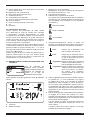
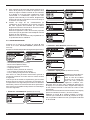
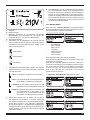
3.3 DESCRIZIONE FUNZIONI VISUALIZZATE SUL
DISPLAY A.
All’accensione della
macchina il display A, per
qualche istante, visualizza: il
numero di articolo della
macchina, la versione, la
data di sviluppo del software.
Qualche secondo dopo sul display A compare la seguente
schermata:
a
b
f
c
d
e
g h
a Prigioniero
b Materiale base
c Materiale del rivetto e relative dimensioni
NOTA: la lunghezza massima del rivetto che può
essere utilizzato è 30mm (1-1/4”)
d Tipo di materiale base
e Indicazione relativa alla qualità della saldatura.
Questo simbolo con la lettera Q indica che i materiali
del prigioniero e del materiale base che sono stati
scelti sono saldabili, poco saldabili oppure non
saldabili (Vedi tabella 1).
buona saldabilità
bassa saldabilità
non saldabili
f Indicazioni/avvertenze durante la fase di saldatura.
Durante le fasi di saldatura questi simboli forniscono
delle indicazioni relative al processo:
f
f sso: indica che il generatore è pronto per
eseguire una saldatura.
f
f sso: Indica che il prigioniero è in contatto con
il materiale base ed il generatore è pronto
per eserguire la saldatura.
f
f lampeggiante: Indica che dopo avere eseguito
la saldatura non è stata s lata la pinza X
della pistola dal prigioniero
f
f lampeggiante: Indica che, dopo aver eseguito la
saldatura, è premuto il pulsante di start e
il microinterruttore all'interno della pistola
durante la carica dei condensatori.
g Valore suggerito della forza della molla posta all’interno
della pistola (se si modi ca della regolazione della
forza si suggerisce di modi care anche il valore
indicato sul display in modo che in futuro questa
modi ca resterà memorizzata. La modi ca rispetto al
valore suggerito sarà indicata da una freccia rivolta
verso l’alto se viene aumentata oppure verso il basso
se viene diminuita)
h Tensione di carica dei condensatori (la modi ca della
regolazione della tensione rispetto al valore suggerito
sarà indicata da una freccia rivolta verso l’alto se viene
aumentata oppure verso il basso se viene diminuita).
Durante la regolazione il valore della tensione
lampeggia ad indicare che il generatore sta lavorando
per raggiungere il valore richiesto.
Quando il valore della tensione lampeggia non è
possibile eseguire la saldatura.
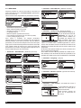
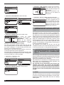
3.3.1 IMPOSTAZIONI
Premere per almeno 2 secondi la manopola G per entrare
nel menu “Process Params” (Parametri di processo).
In questo menu sono disponibili i seguenti parametri:
- Stud Material
- Base material
- Spring Force
- Language
- Measure sistem
- LCD contrast
- Facrory Setup
Per entrare all’interno di ciascun parametro selezionarlo

6
ruotando la manopola G quindi premerla per meno di 2
secondi.
Una volta entrati nel parametro ruotare la manopola G
per eseguire la scelta, quindi premerla nuovamente per
un tempo minore di 2 secondi per confermare la scelta e
ritornare nel menù dell'elenco dei parametri. Per ritornare
alla schermata iniziale premere la manopola G per più di
2 secondi.
• Parametro “Stud Material” (Materiale prigioniero)
• Parametro “Base Material” (Materiale base)
• Parametro “Spring Force” (Forza della molla)
Mediante la manopola Q è
possibile variare il valore.
Nota: qualora venga modi-
cata la forza sulla pistola
rispetto al valore proposto,
suggeriamo di variare questo valore. Il nuovo valore mo-
di cato comparirà sul display con a anco una freccia ri-
volta verso il basso se il valore é stato diminuito oppure
verso l'alto se il valore é stato aumentato.
In base alle scelte eseguite sul display è indicata la tensio-
ne e la forza da utilizzare.
Mediante la manopola G é possibile modi care la tensione
mentre mediante la manopola Q, posta sulla pistola, è pos-
sibile modi care la forza che è visualizzata sulla scala P.
• Parametro “Language” (lingua)
• Parametro “Measure system” (Sistema di misura)
• Parametro “LCD contrast” (Contrasto del display)
Mediante la manopola G è
possibile variare il valore da
0 al 100%
Questa funzione consente di
rendere più o meno lumino-
so il display A.
• Parametro “Factory setup” (Impostazioni di fabbrica)
Mediante la manopola G è
possibile selezionare ON e
premendola brevemente sul
display compare la scritta
Factory Done che dimostra
la riusita del reset.
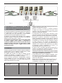
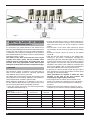
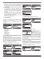
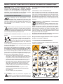
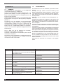
4 PRINCIPIO DI FUNZIONAMENTO DELLA
SALDATURA DI PRIGIONIERI FILETTATI CON
INNESCO A PUNTA DI ACCENSIONE (Fig. 3)
Il prigioniero viene inserito nella pinza X (fase 1), quindi
viene posizionato e premuto con la sua punta di innesco
direttamente sulla super cie della lamiera da saldare
(fase 2). La molla della pistola preme il prigioniero contro
il metallo, il comando di start fa iniziare il passaggio di
corrente che vaporizza la punta di innesco consentendo la
generazione dell'arco che si propaga su tutta la super cie
del prigioniero (fase 3) che viene spinto sulla super cie
metallica. Il metallo fuso solidi ca saldando il prigioniero
(fase 4).
L'estrazione della pistola deve avvenire perfettamente
allineata con il perno per non deformare la pinza e
assicurarne così una lunga vita (fase 5).

7
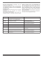
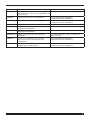
5 SALDABILITA' DI COMBINAZIONI TIPICHE FRA
PRIGIONIERO E METALLO BASE PER SALDATURA
CON SCARICA DI CONDENSATORI. (Tabella 1)
E' importante studiare con particolare attenzione la resistenza
e la deformazione nel punto di saldatura fra prigioniero
e metallo base. Nel caso dell'acciaio, si deve prestare
particolare attenzione alla fragilità da indurimento.
Il materiale e la resistenza del prigioniero sono soggetti a
tolleranza ristretta. il contenuto di carbonio nei prigionieri
lettati in acciaio deve essere < 0,20%.
La super cie del metallo base deve essere pulita. Strati
di vernice, ruggine, scorie, grasso e rivestimenti di
metalli non saldabili, devono essere rimossi dalla zona di
saldatura. Questo si deve fare con mezzi idonei. I metalli
di base con strati di scorie e ruggine devono essere
perfettamente puliti.
6 SALDATURA
Questa tecnologia permette di saldare prigionieri lettati su
super ci pulite, ma non ossidate, di acciaio dolce, acciaio
galvanizzato, acciaio inox, alluminio e ottone.
La rapidità del processo non altera le super ci sul lato
opposto alla saldatura. La saldatura non è possibile su
acciaio temperato, metallo ossidato o verniciato.
Prima di iniziare la produzione è indispensabile, effettuare
alcune saldature di prova per determinare la corretta
regolazione del generatore e la taratura della pistola (forza
della molla) operando come segue:
• inserire il prigioniero scelto nella pinza X (preventivamente
regolata come descritto in Fig. 2)
• disporre la lamiera di base in condizioni identiche
a quelle che saranno le condizioni di lavoro come
spessore, area dei collegamenti di massa, dimensioni
del pezzo, qualità del materiale.
• I morsetti del cavo di massa vanno collocati in modo
simmetrico ed il più vicino possibile al punto di saldatura.
• Attivare il generatore tramite l'interruttore luminoso E.
• Impugnare la pistola e posizionare il prigioniero sul
punto di saldatura evitando di dare colpi e quindi di
danneggiare la punta d'innesco del prigioniero. Premere
il pulsante O e, tenendolo premuto, spingere la pistola
in modo uniforme e non rapido. Al raggiungimento
della giusta pressione si attiverà automaticamente la
saldatura. Se la super cie del materiale su cui saldare
il prigioniero è piana, consigliamo di montare i tre
distanziali Z dopo avere svitato le viti Y.
• In questo caso si consiglia di spingere la pistola no a
portare i tre distanziali in battuta sul pezzo e quindi di
premere il pulsante per attivare la saldatura.
Queste procedure sono richieste per avere la stessa
pressione del prigioniero sul materiale base e quindi
una maggiore qualità della saldatura.
• I valori di tensione e forza, consigliati sul display, sono
da intendersi come base di partenza per determinare
la corretta regolazione del generatore e della taratura
della forza della pistola.
• Questi valori sono stati sperimentati su provini di “ma-
teriale base” di spessore 2 mm per acciaio e acciao
inossidabile e di spessore 1,2 mm per alluminio.
Fig. 3
1 2 3 4 5
Materiale prigionieri
Metallo base
Acciaio ramato con
più di 0.2 C%
Acciaio inossi-
dabile 304/316
Al Mg 3 AI Si 12 Al 99,5
Acciaio no a 0.30 C % A A - - -
Acciaio zincato B B - - -
Acciaio inossidabile 304/316 A A - - -
Al 99,5 - - A B B
Al Mg 3 - - B A B
Al Si 12 - - B A B
Buona saldabilità: A Bassa saldabilità: B Non saldabile: -
Tab. 1

8
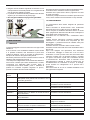
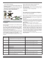
• Eseguire alcune saldature regolando la tensione con la
manopola G e la forza della pistola con la regolazione Q
no ad ottenere saldature perfette.
• La pistola va estratta tenendola perfettamente allineata
al perno per non deformare la pinza (Fig4).
• Non eseguire saldature su prigionieri già saldati.
OK
NO
OK
NO
Fig. 4
7 MANUTENZIONE
7.1 ORDINARIA
Conservare leggibili e chiare le indicazioni e le gure sulla
saldatrice.
Il cavo rete ed i cavi di saldatura debbono essere isolati
e in perfette condizioni; fare attenzione ai punti dove
subiscono essioni: vicino ai morsetti di collegamento,
alle pinze di massa e all'ingresso nella pistola.
Mantenere puliti e ben serrati i connettori della corrente di
saldatura alle prese B e C (vedi Fig. 1)
I morsetti per il collegamento con il metallo base debbono
fare un buon contatto per evitare riscaldamento, scintille,
circolazione non bilanciata della corrente, danni al
componente dove vanno saldati i perni e saldature di
qualità non costante. Impedire l'ingresso di sporco,
polvere e limatura all'interno della saldatrice.
Garantire sempre la circolazione dell'aria di raffreddamento.
Controllare che il ventilatore funzioni regolarmente.
Veri care che le pinze serrino bene i prigionieri con tutte
le molle di contatto.
Il mandrino portapinze deve scorrere libero per tutta la sua
corsa, senza variazioni dovute ad attriti o corpi estranei.
7.2 STRAORDINARIA
La manutenzione deve essere eseguita da personale
quali cato
Alcune anomalie di funzionamento sono evidenziate
dall'accensione di un codice di errore su display A.
Prima di aprire la saldatrice attendere almeno 5 minuti
dallo spegnimento dell'interruttore E inoltre scollegare la
spina dalla presa di alimentazione.
Controllare con un voltmetro che i condensatori siano
scarichi.
Togliere polvere, frammenti e limature metallica dalla
macchina con cura usando aria compressa per non
danneggiare o proiettare frammenti metallici sulle parti
elettroniche o elettriche.
Veri care che tutti i connettori siano inseriti a fondo.
Veri care che tutti i terminali del circuito di saldatura siano
ben serrati.
Dopo aver eseguito una riparazione, fare attenzione
a riordinare il cablaggio in modo che vi sia un sicuro
isolamento tra il lato primario ed il lato secondario della
macchina. Evitare che i li possano andare a contatto
con parti in movimento o parti che si riscaldano durante
il funzionamento. Rimontare tutte le fascette come
sull'apparecchio originale in modo da evitare che, se
accidentalmente un conduttore si rompe o si scollega,
possa avvenire un collegamento tra il primario ed il
secondario.
Rimontare inoltre le viti con le rondelle dentellate come
sull'apparecchio originale.
Codice di
errore
Anomalia Soluzione
WARNING 1 Signi ca che il pulsante ed il microinterruttore
della pistola sono premuti nel momento in cui si
accende il generatore.
Rilasciare il pulsante di start.
ERROR 2 Signi ca che il relè RL1 è difettoso. Circuito di potenza difettoso.
Contatare il servizio assistenza.
ERROR 3 Signi ca che il relè RL1 è difettoso. Circuito di potenza difettoso.
Contatare il servizio assistenza.
ERROR 4 Signi ca che l’SCR è in corto circuito. Contatare il servizio assistenza.
ERROR 5 Signi ca che vi è un difetto nel circuito di carica
dei condensatori
Contatare il servizio assistenza.
ERROR 7 Signi ca che vi è un difetto nel circuito di carica
dei condensatori
Contatare il servizio assistenza.
WARNING TH
Signi ca che è intervenuta la protezione termica. E’ necessario a endere alcuni minu senza
spegnere la saldatrice.
ERROR 9
Signi ca che vi è un dife o nel circuito che
misura la tensione ai capi dei condensatori.
Circuito di potenza difettoso.
Contatare il servizio assistenza.
ERROR 10
Signi ca che vi è un corto circuito nel circuito di
scarica dei condensatori.
Circuito di potenza difettoso.
Contatare il servizio assistenza.

9
INSTRUCTION MANUAL FOR CAPACITOR DISCARGE WELDING MACHINE
IMPORTANT: BEFORE STARTING THE EQUIPMENT,
READ THE CONTENTS OF THIS MANUAL, WHICH
MUST BE STORED IN A PLACE FAMILIAR TO ALL US-
ERS FOR THE ENTIRE OPERATIVE LIFE-SPAN OF THE
MACHINE.
THIS EQUIPMENT MUST BE USED SOLELY FOR WELD-
ING OPERATIONS.
1 SAFETY PRECAUTIONS
WELDING AND ARC CUTTING CAN BE HARM-
FUL TO YOURSELF AND OTHERS. The user must
therefore be educated against the hazards, summarized be-
low, deriving from welding operations. For more detailed in-
formation, order the manual code 3.300.758
NOISE
These power source alone do not produce noise
levels exceeding 80 dB. The welding procedure,
however, may produce noise levels in excess of
80 dB. in which case the machine operator must take the
necessary safety precautions as prescribed by the na-
tional safety regulation.
ELECTRIC AND MAGNETIC FIELDS INFORMATION
· Electric current following through any con-
ductor causes localized Electric and Mag-
netic Fields (EMF). Welding/cutting current
creates EMF elds around cables and pow-
er sources.
· The magnetic elds created by high currents may affect
the operation of pacemakers. Pacemaker wearers are
prohibited from using the machine or approach the
cables.
· Exposure to EMF elds in welding/cutting may have
other health effects which are now not known.
· All operators should use the followingprocedures in or-
der to minimize exposure to EMF elds from the welding/
cutting circuit:
- Route the electrode and work cables together
- Secure them with tape when possible.
- Never coil the electrode/torch lead around your body.
- Do not place your body between the electrode/torch
lead and work cables. If the electrode/torch lead
cable is on your right side, the work cable should also
be on your right side.
- Connect the work cable to the workpiece as close as
possible to the area being welded/cut.
- Do not work next to welding/cutting power source.
EXPLOSIONS
· Do not weld in the vicinity of containers under
pressure, or in the presence of explosive dust,
gases or fumes.
· All cylinders and pressure regulators used in welding
operations should be handled with care.
ELECTROMAGNETIC COMPATIBILITY
This machine is manufactured in compliance with the in-
structions contained in the standard IEC 60974-10 (CL.
A), and must be used solely for professional purposes
in an industrial environment. There may be potential dif-
culties in ensuring electromagnetic compatibility in non-
industrial environments.
DISPOSAL OF ELECTRICAL AND ELECTRONIC
EQUIPMENT.
Do not dispose of electrical equipment together
with normal waste! Electrical equipment that has
reached the end of its life must be collected separately
and returned to an environmentally compatible recycling
facility. As the owner of the equipment, you should get
information on approved collection systems from our lo-
cal representative.
Extra precautions are to be observed when working
on elevated positions.
IN CASE OF MALFUNCTIONS, REQUEST ASSISTANCE
FROM QUALIFIED PERSONNEL.
1.1 WARNING LABEL
The following numbered text corresponds to the label
numbered boxes.
B. Drive rolls can injure ngers.
C. Welding wire and drive parts are at welding voltage
during operation - keep hands and metal objects
away.
1 Electric shock from welding electrode or wiring can kill.
1.1 Wear dry insulating gloves. Do not touch electrode
with bare hand. Do not wear wet or damaged gloves.

10
1.2 Protect yourself from electric shock by insulating
yourself from work and ground.
1.3 Disconnect input plug or power before working on
machine.
2 Breathing welding fumes can be hazardous to your
health.
2.1 Keep your head out of fumes.
2.2 Use forced ventilation or local exhaust to remove
fumes.
2.3 Use ventilating fan to remove fumes.
3 Welding sparks can cause explosion or re.
3.1 Keep ammable materials away from welding.
3.2 Welding sparks can cause res. Have a re extinguisher
nearby and have a watchperson ready to use it.
3.3 Do not weld on drums or any closed containers.
4 Arc rays can burn eyes and injure skin.
4.1 Wear hat and safety glasses. Use ear protection and
button shirt collar. Use welding helmet with correct
shade of lter. Wear complete body protection.
5 Become trained and read the instructions before
working on the machine or welding.
6 Do not remove or paint over (cover) label.
2 GENERAL DESCRIPTIONS
2.1 SPECIFICATIONS
The machine has been designed and built for welding
ferrous and non-ferrous stud bolts, Ø 3-4,5-6 and 8 mm.
This welding system uses the extremely rapid (2-3 ms)
discharge of a battery of charged capacitors, which allows
the welding of stud bolts with contact point start-up.
2.2 EXPLANATION OF THE TECHNICAL
SPECIFICATIONS LISTED ON THE MACHINE
PLATE
This machine is manufactured according to the following
standards: IEC 60974.1 / IEC 60974.10 (CL. A) / IEC
61000-3-11 / IEC 61000-3-12.
N° Serial number, which must be indicated on any
request regarding the welding machine
1
~
Single-phase transformer-rectier with device
for charging and discharging the capacitors
U0 Secondary open-circuit voltage
E Welding energy
C Capacity value
Uc Voltage adjustable on the capacitors
U1 Rated supply voltage. The machine is set up for
voltages of 120V and 240V with automatic
voltage change.
1-50/60Hz 50- or 60-Hz single-phase power supply
I1 Max Max. absorbed current at the corresponding
supply voltage.
I1 Eff This is the current absorbed considering the duty
cycle at the corresponding input voltage.
IP23S Protection rating for the housing. Grade 3 as the
second digit means that this equipment may be
stored, but it is not suitable for use outdoors in
the rain, unless it is protected
S
Suitable for use in high-risk environments.
Note:
The machine has also been designed for use in
environments with a pollution rating of 3. (See IEC 60664).
2.3 DESCRIPTION OF PROTECTIVE DEVICES
2.3.1 Thermal protection
This machine is protected by a thermostat, which prevents
the machine from operating if the allowable temperatures
are exceeded. Under these conditions the fan keeps
running and the display will show "Warning 08".
3 INSTALLATION
Only skilled personnel should install the machine. All
connections must be carried out according to current
regulations, and in full observance of safety laws.
1. Do not place the welding machine on oor with
inclination greater than 10°.
Air must circulate freely, both incoming and outgoing,
and the welding machine must be protected from entry
by liquids, dirt, metal lings, etc.
2. Make sure that the supply voltage matches the
voltage indicated on the specications plate of the
welding machine. When mounting a plug, make sure
it has an adequate capacity, and that the yellow/green
conductor of the power supply cable is connected to
the earth pin.
The capacity of the overload cutout switch or fuses
installed in series with the power supply must be
equivalent to the absorbed current I1 of the machine.
Any extension cords must be sized appropriately for
the absorbed current I1.
If the power supply is 115V, the machine may run for
voltages between 96V and 140V.
If the power supply is 230V, the machine may run for
voltages between 190V and 260V.
The machine must be switched off when changing
the power supply.
3. Pacemaker wearers are prohibited from using the
machine or approach the cables.
4. Fully insert the earth cable plug into the socket B and
turn clockwise.
5. Fully insert the gun plug into the socket C and turn
clockwise.
6. Turn on the welding machine using the E switch.
(start-up and shutdown should not be repeated
frequently, because dissipating the energy contained
in the capacitors may cause overheating and damage).
7. To limit exposure to the magnetic eld, keep the gun
cable on the side of the hand holding it, avoiding
wrapping the cable around.
3.1 DESCRIPTION OF THE EQUIPMENT
A- Display for the setting and control of welding operations
B- Positive output terminal
C- Negative output terminal

11
D- Torch trigger connector
E- Main switch
F- Fuse Ø 6.3x32 (delayed type). The equipment is tted
with a 12A-T fuse.
G- Knob for the setting and control of welding operations.
3.2 GUN DESCRIPTION
K- Gun body
L- Grip
M- Control cable
N- Welding current cable
O- Welding command button (works only with the gun
pressed against the sheet metal)
P- Force setting indicator
Q- Force adjustment screw (increases when turned clock
wise)
R- Ring to hold spacer Z
S- Clamp locking ring-nut
T- Safety bellows
U- Holding screws for ring R
V- Screw to adjust stud bolt protrusion
W- Holding nut.
X- Stud bolt gripping clamp
Y- Screw
Z- Spacer
X
M N L
S Z T
R U
O P QK
Fig. 2
X W V
1÷1,5 mm
Y
3.2.1 Preparing the gun
Always use high-quality studs with contact point start-
up for capacitor discharge welding, which comply with
standards and are made of a metal compatible with the
welding to be done.
Having selected the stud bolt to be welded for type,
diameter, length and material, use and adjust the gripping
A
B C
G
D
E
F
Fig. 1

12
clamp according to the corresponding diameter.
Insert the stud bolt in the clamp X so that it is rmly held
in place by the four springs.
Adjust the protrusion of the stud bolt from the front of the
clamp to 1 ÷ 1.5 mm using the screw V, then tighten with
the nut W (gure 2).
Insert the clamp X into the chuck of the gun (g. 2), press
until you feel it rest all the way down, and tighten the nut
S using the 17-mm hexagon wrench provided.
3.3 DESCRIPTION OF FUNCTIONS SHOWN ON THE
DISPLAY A.
When the machine is switched
on, for a few seconds the
display A will show the
machine item number, version
and development date of the
software.
A few seconds later, the following screen will appear on
the display A:
a
b
f
c
d
e
g h
a Stud bolt
b Base material
c Rivet material and dimensions
NOTE: the maximum rivet length that can be used is
30mm (1-1/4”)
d Type of base material
e Indication as to weld quality.
This symbol with the letter Q indicates that the stud
material and the base material that have been selected
are weldable, poorly weldable or non-weldable (See
table 1).
good weldability
poor weldability
non-weldable
f Indications/warnings during the welding phase.
During welding phases these symbols provide
process-related indications:
f
f steadily lit: indicates that the generator is ready
to carry out a welding operation.
f
f steadily lit: indicates that the stud bolt is in
contact with the base material and
the generator is ready to carry out the
welding operation.
f
f ashing: indicates that, after the welding was
completed, the gripping clamp X of
the gun was not removed from the
stud bolt.
f
f ashinge: indicates that, after the welding
was completed, the start button
and microswitch inside the gun
were pressed during charging of the
capacitors.
g Value suggested by the force of the spring inside the
gun (if the force setting is changed, it is recommended
also to change the value indicated on the display so
that in the future this change will remain memorized.
The change from the suggested value will be indicated
by an arrow pointing upward if it is increased or
downward if it is decreased).
h Charge voltage of the capacitors (if the voltage
setting is changed from the suggested value, it will
be indicated by an arrow pointing upward if it is
increased or downward if it is decreased).
During the adjustment, the voltage value will ash to
indicate that the generator is working to reach the
requested value.
Whilst the voltage value is ashing, it is not possible
to perform any welding operation.
3.3.1 SETTINGS
Press the knob G for at least 2 seconds to open the
“Process Params” (Process Parameters) menu.
The following parameters are selectable from this menu:
- Stud Material
- Base material
- Spring Force
- Language
- Measure system
- LCD contrast
- Factory Setup
To access each parameter, select it by turning the knob G
and then press it for less than 2 seconds.
Once you have accessed the parameter, turn the knob G
to make the desired choice and then press it again for less
than 2 seconds to conrm the choice made and go back
to the menu with the list of parameters. To go back to the
initial screen, press the knob G for more than 2 seconds.

13
• “Stud Material” parameter.
• “Base Material” parameter.
• “Spring Force” parameter.
The value can be changed by
means of the knob Q.
Note: if the force on the gun
is changed from the pro-
posed value, we recommend
adjusting this value. The
newly changed value will appear on the display and next to
it an arrow pointing downward if the value was decreased
or upward the value was increased.
Based on the choices made, the force and voltage to be
used will be indicated on the display.
It is possible to change the voltage by means of the knob
G, whereas the force displayed on the scale P can be
changed by means of the knob Q.
• “Language” parameter.
• “Measure system” parameter.
• “LCD contrast” parameter.
The value can be changed
from 0 to 100% by means of
the knob G.
This function enables you
to increase or reduce the
brightness of the display A.
• “Factory setup” parameter.
“ON” can be selected by
turning the knob G and
pressing it briey; the
message “Factory Done”
will appear to conrm that
the reset was successful.
4 OPERATING PRINCIPLE OF WELDING THREADED
STUD BOLTS WITH CONTACT POINT START-UP
(Fig. 3)
The stud bolt is inserted in the clamp X (phase 1), then
positioned and pressed with its start-up contact directly
against the surface of the sheet metal to be welded (phase
2). The spring of the gun presses the stud bolt against
the metal, the start command begins sending current
which melts the start-up contact, and the electrical arc
is propagated along the entire surface of the stud bolt
(phase 4) pushed against the metal surface. The molten
metal solidies, thereby welding the stud bolt (phase 5).
The gun must be extracted in perfect alignment with the
bolt to avoid deforming the clamp, and thus ensuring its
long life-span (phase 6).

14
Stud material
Base metal
Copper plated steel
up to 0.2 C%
Stainless steel
304/316
Al Mg 3 AI Si 12 Al 99,5
Steel up to 0.30 C % A A - - -
Galvanized steel B B - - -
Stainless steel 304/316 A A - - -
Al 99,5 - - A B B
Al Mg 3 - - B A B
Al Si 12 - - B A B
High weldability: A Low weldability: B Not weldable: -
Tab. 1
5 WELDABILITY OF TYPICAL STUD BOLT/BASE
METAL COM BINATIONS FOR CAPACITOR
DISCHARGE WELDING. (Table 1)
It is important to pay careful attention to the resistance and
deformity at the welding point between the stud bolt and base
metal. In the case of steel, you must pay particular attention
to brittleness. The material and resistance of the stud bolt
have limited tolerance; the carbon content in steel threaded
stud bolts must be < 0.20%.
The surface of the base metal must be clean. Layers
of paint, rust, waste, grease and non-weldable metal
coatings must be removed from the welding area. This
must be done using appropriate means. Base metals
with layers of waste and rust must be cleaned thoroughly.
6 WELDING
This technology makes it possible to weld stud bolts on
clean, but not oxidized, surfaces of mild steel, galvanized
steel, stainless steel, aluminum and brass.
The rapidity of the process does not alter the surfaces on the
side opposite from the welding. Welding is not possible on
case-hardened steel, oxidized or painted metal.
Before beginning production it is essential to carry out a
few test welds to determine the proper setting of the power
source and gun (spring force), proceeding as follows:
• Insert the chosen stud bolt in the clamp X (previously
adjusted as described in Fig. 2).
• Arrange the base sheet metal in conditions identical to
those that will be used for the job in terms of thickness,
earth connection area, size of the workpiece, material
quality.
• The terminals of the earth cable should be placed
symmetrically, and as close as possible to the welding
point.
• Activate the power source by means of the lighted
switch E.
• Hold the gun and place the stud on the welding spot,
avoiding to give blows, consequently damaging the
striking tip of the stud. Press the trigger O and, holding it
pressed, push the gun evenly and not quickly. Once the
right pressure is reached, the weld will be automatically
activated. If the surface of the material on which the stud
bolt is to be welded is at, we recommend mounting the
three spacers Z after rst unscrewing the screws Y
• In this case it is recommended to push the gun until the
three spacers are in touch with the piece and then press
the trigger to activate the welding.
These procedures are required to obtain the same
pressure of the stud on the base material and
consequently a higher quality of the weld.
• The voltage and force values recommended on the
display are intended as a starting point for calculating
the correct power source setting and for calibrating
gun force.
• These values have been tested on samples of “base
materials” (2 mm thick for steel and stainless steel and
Fig. 3
1 2 3 4 5

15
1.2 mm thick for aluminium).
• Carry out a few welds, adjusting the voltage using the knob
G, and the force of the gun using the setting knob Q, until
the welding is perfect.
• The gun should be removed keeping it perfectly aligned
with the bolt, to avoid deforming the clamp (Fig4).
• Do not make welds to welded stud bolts.
OK
NO
OK
NO
Fig. 4
7 MAINTENANCE
7.1 ROUTINE
Keep all instructions and gures on the welding machine
clear and legible.
The mains cable and welding cables must be insulated
and in perfect condition; be careful with the tips, which ex:
near the connection terminals, earth clamps and gun input.
Keep the welding current connectors to sockets B and C
clean and rmly tightened (see Fig. 1)
The terminals for connecting to the base metal must
make good contact to avoid overheating, sparks, uneven
current circulation, damage to the components where the
pins are welded, and welding of uneven quality.
Prevent dirt, dust and lings from getting into the welding
machine.
Always make sure the cooling air circulates freely.
Make sure that the fan functions properly.
Make sure that the clamps hold the stud bolts rmly, with
all contact springs.
The clamp must slide freely throughout its length, without
changes due to friction or foreign matter.
7.2 SPECIAL
Only quali ed personnel should perform maintenance.
Some functional errors are highlighted by the appearance
of an error code on the display A.
Wait at least 5 minutes after shutting off the switch E
before opening the welding machine, and unplug the plug
from the power socket.
Use a volt meter to make sure that the capacitors are
discharged.
Carefully remove any dust, metal fragments and lings
from the machine using compressed air to avoid damaging
or projecting metal fragments onto the electronic or
electrical parts.
Make sure that all connectors are fully inserted.
Make sure that all welding circuit terminals are rmly
tightened.
After making a repair, make sure to rearrange the wiring
so that there is secure insulation between the primary and
secondary sides of the machine. Do not allow wires to
come into contact with moving parts or those that heat
up during operation. Reassemble all of the clamps as they
were on the original machine, to prevent an accidental
connection between the primary and secondary circuits if
a conductor should break or disconnect.
Also remount the screws with geared washers as on the
original equipment.
Error code Problem Solution
WARNING 1 It means that the gun start button and microswitch
are pressed at the moment the generator is turned
on.
Release the start button.
ERROR 2 It means that the relay RL1 is faulty. Power circuit fault.
Contact the technical support service.
ERROR 3 It means that the relay RL1 is faulty. Power circuit fault.
Contact the technical support service.
ERROR 4 It means that the SCR has short circuited Contact the technical support service.
ERROR 5 It means that there is a fault in the capacitor
charging circuit
Contact the technical support service.
ERROR 7 It means that there is a fault in the capacitor
charging circuit
Contact the technical support service.
WARNING TH
It means that the thermal protector has tripped.
Wait a few minutes without turning off the welding
machine.
ERROR 9
It means that there is a fault in the circuit that
measures the voltage across the capacitors.
Power circuit fault.
Contact the technical support service.
ERROR 10
It means that there is a short circuit in the
capacitor discharging circuit.
Power circuit fault.
Contact the technical support service.

16
BETRIEBSANLEITUNG FÜR KONDENSATOR-STOSSENTLADUNGSSCHWEISSMASCHINE
WICHTIG: Vor der Inbetriebnahme des Geräts den In-
halt der vorliegenden Betriebsanlei- tung aufmerksam
durchlesen; die Betriebs- anleitung muß für die gesamte
Lebensdauer des Geräts an einem allen interessierten
Personen bekannten Ort aufbewahrt werden.
Dieses Gerät darf ausschließlich zur Ausführ- ung von
Schweißarbeiten verwendet werden.
1 SICHERHEITSVORSCHRIFTEN
DAS LICHTBOGENSCHWEISSEN UND -SCHNEI-
DEN KANN FÜR SIE UND ANDERE GESUND-
HEITSSCHÄDLICH SEIN; daher muß der Benutzer über die
nachstehend kurz dargelegten Gefahren beim Schweißen
unterrichtet werden. Für ausführlichere Informationen das
Handbuch Nr. 3.300758 anfordern.
LÄRM
Dieses Gerät erzeugt selbst keine Geräusche, die
80 dB überschreiten. Beim Plasmaschneid- und
Plasmaschweißprozeß kann es zu einer Geräu-
schentwicklung kommen, die diesen Wert überschreitet.
Daher müssen die Benutzer die gesetzlich vorgeschrie-
benen Vorsichtsmaßnahmen treffen.
ELEKTROMAGNETISCHE FELDER - Schädlich können
sein:
• Der elektrische Strom, der durch einen
beliebigen Leiter ießt, erzeugt elektromag-
netische Felder (EMF). Der Schweiß- oder
Schneidstrom erzeugt elektromagnetische
Felder um die Kabel und die Stromquellen.
• Die durch große Ströme erzeugten magnetischen Fel-
der können den Betrieb von Herzschrittmachern stören.
Trägern von Herzschrittmachern ist der Gebrauch
der Maschine und die Annäherung an die Kabel ver-
boten.
• Die Aussetzung an die beim Schweißen oder Schnei-
den erzeugten elektromagnetischen Felder kann bislang
unbekannte Auswirkungen auf die Gesundheit haben.
Um die Risiken durch die Aussetzung an elektromagne-
tische Felder zu mindern, müssen sich alle SchweißerIn-
nen an die folgenden Verfahrensweisen halten:
- Sicherstellen, dass das Massekabel und das Kabel
der Elektrodenzange oder des Brenners nebeneinan
der bleiben. Die Kabel nach Möglichkeit mit einem
Klebeband aneinander befestigen.
- Das Massekabel und das Kabel der Elektrodenzange
oder des Brenners nicht um den Körper wickeln.
- Sich nicht zwischen das Massekabel und das Kabel
der Elektrodenzange oder des Brenners stellen. Wenn
sich das Massekabel rechts vom Schweißer bzw. der
Schweißerin bendet, muss sich auch das Kabel der
Elektrodenzange oder des Brenners auf dieser Seite
benden.
- Das Massekabel so nahe wie möglich an der Schweiß-
oder Schneidstelle an das Werkstück anschließen.
- Nicht in der Nähe der Stromquelle arbeiten.
EXPLOSIONSGEFAHR
• Keine Schneid-/Schweißarbeiten in der Nähe von
Druckbehältern oder in Umgebungen ausführen, die
explosiven Staub, Gas oder Dämpfe enthalten. Die für den
Schweiß-/Schneiprozeß verwendeten Gasaschen und
Druckregler sorgsam behandeln.
ELEKTROMAGNETISCHE VERTRÄGLICHKEIT
Dieses Gerät wurde in Übereinstimmung mit den Angaben
der harmonisierten Norm IEC 60974-10 (Cl. A) konstruiert
und darf ausschließlich zu gewerblichen Zwecken und nur
in industriellen Arbeitsumgebungen verwendet werden. Es
ist nämlich unter Umständen mit Schwierigkeiten verbunden
ist, die elektromagnetische Verträglichkeit des Geräts in an-
deren als industriellen Umgebungen zu gewährleisten.
Entsorgung der Elektro- und Elektronikgeräte
Elektrogeräte dürfen niemals gemeinsam mit ge-
wöhnlichen Abfällen entsorgt werden! In Überein-
stimmung mit der Europäischen Richtlinie 2002/96/
EG über Elektro- und Elektronik-Altgeräte und der jeweiligen
Umsetzung in nationales Recht sind nicht mehr verwendete
Elektrogeräte gesondert zu sammeln und einer Anlage für
umweltgerechtes Recycling zuzuführen. Als Eigentümer der
Geräte müssen Sie sich bei unserem örtlichen Vertreter über
die zugelassenen Sammlungssysteme informieren. Die Um-
setzung genannter Europäischer Richtlinie wird Umwelt und
menschlicher Gesundheit zugute kommen!
IM FALLE VON FEHLFUNKTIONEN MUSS MAN SICH AN
EINEN FACHMANN WENDEN.
Besondere Vorsichtsmaßnahmen müssen bei der
Verwendung in der Höhe genommen werden.
1.1 WARNHINWEISSCHILD
Die Nummerierung der Beschreibungen entspricht der
Nummerierung der Felder des Schilds.
B. Die Drahtförderrollen können Verletzungen an den Hän-
den verursachen.
C. Der Schweißdraht und das Drahtvorschubgerät stehen
während des Schweißens unter Spannung. Die Hände
und Metallgegenstände fern halten.
1. Von der Schweißelektrode oder vom Kabel verursachte
Stromschläge können tödlich sein. Für einen angemes-
senen Schutz gegen Stromschläge Sorge tragen.
1.1 Isolierhandschuhe tragen. Die Elektrode niemals mit
bloßen Händen berühren. Keinesfalls feuchte oder
schadhafte Schutzhandschuhe verwenden.
1.2 Sicherstellen, dass eine angemessene Isolierung vom
Werkstück und vom Boden gewährleistet ist.
1.3 Vor Arbeiten an der Maschine den Stecker ihres Netzka-
bels abziehen.
2. Das Einatmen der beim Schweißen entstehenden
Dämpfe kann gesundheitsschädlich sein.
2.1 Den Kopf von den Dämpfen fern halten.
2.2 Zum Abführen der Dämpfe eine lokale Zwangslüftungs-
oder Absauganlage verwenden.
2.3 Zum Beseitigen der Dämpfe einen Sauglüfter verwen-
den.
3. Die beim Schweißen entstehenden Funken können Ex-
plosionen oder Brände auslösen.
3.1 Keine entammbaren Materialien im Schweißbereich
aufbewahren.

17
3.2 Die beim Schweißen entstehenden Funken können
Brände auslösen. Einen Feuerlöscher in der unmittel-
baren Nähe bereit halten und sicherstellen, dass eine
Person anwesend ist, die ihn notfalls sofort einsetzen
kann.
3.3 Niemals Schweißarbeiten an geschlossenen Behältern
ausführen.
4. Die Strahlung des Lichtbogens kann Verbrennungen an
Augen und Haut verursachen.
4.1 Schutzhelm und Schutzbrille tragen. Einen geeigneten
Gehörschutztragen und bei Hemden den Kragen zu-
knöpfen. Einen Schweißerschutzhelm mit einem Filter
mit der geeigneten Tönung tragen. Einen kompletten
Körperschutz tragen.
5. Vor der Ausführung von Arbeiten an oder mit der Ma-
schine die Betriebsanleitung lesen.
6. Die Warnhinweisschilder nicht abdecken oder entfer-
nen.
2 ALLGEMEINE BESCHREIBUNG
2.1 TECHNISCHE ANGABEN
Die Maschine wurde zum Schweißen von Gewindebol-
zen aus Eisen- und Nichteisenmetallen mit einem Durch-
messer von 4, 5 oder 6 mm projektiert und konstruiert.
Bei diesem Schweißverfahren wird durch die extrem
schnelle Entladung (2-3 ms) einer Kondensatorbatterie
ein Lichtbogen erzeugt, der das Bolzenschweißen mit
Spitzenzündung erlaubt.
2.2 ERLÄUTERUNG DER TECHNISCHEN DATEN,
DIE AUF DEM LEISTUNGSSCHILD DER MASCHI-
NE ANGEGEBEN SIND
Die Konstruktion des Geräts entspricht den folgenden
Normen: IEC 60974.1 - IEC 60974.3 -IEC 60974.10 Cl.
A - IEC 61000-3-11- IEC 61000-3-12.
Nr. Seriennummer; sie muss bei allen Anfragen
zur Schweißmaschine stets angege-
ben werden.
1
~
Einphasen-Transformator/Gleichrichter mit
Vorrichtung zum Laden und Entladen von
Kondensatoren
U0 Leerlauf-Sekundärspannung
E Schweißenergie
C Kapazität
Uc Einstellbare Kondensatorspannung
U1 Nennspannung. Die Maschine kann mit den
Spannungen 115V und 230V gespeist wer-
den; die Spannungsumschaltung erfolgt
automatisch.
1-50/60Hz Einphasen-Stromversorgung 50 oder 60 Hz
I1 Max. Maximale Stromaufnahme bei der ents-
pre chenden Speisespannung
I1eff Dies ist der Höchstwert der effektiven
Stromaufnahme bei Berücksichtigung der
relativen Einschaltdauer.
IP23S Schutzart des Gehäuses.
Die zweite Ziffer 3 gibt an, dass dieses
Gerät bei Niederschlägen zwar im Freien
gelagert, jedoch nicht ohne geeigneten
Schutz betrieben werden darf.
S
Geeignet zum Betrieb in Umgebungen mit
erhöhter Gefährdung.
ANMERKUNGEN:
Das Gerät ist außerdem für den Betrieb in Umgebungen
mit Verunreinigungsgrad 3 konzipiert. (Siehe IEC 60664).
2.3 BESCHREIBUNG DER SCHUTZEINRICHTUNGEN
2.3.1 Thermischer Schutz
Dieses Gerät wird durch einen Thermostaten geschützt,
der, wenn die zulässige Temperatur überschritten wird,
den Betrieb der Maschine sperrt. In diesem Zustand bleibt
der Lüfter eingeschaltet und auf der Anzeige erscheint der
Fehlerkode "Warning 8".
3 INSTALLATION
Die Installation der Maschine muss durch Fachpersonal
erfolgen. Alle Anschlüsse müssen nach den geltenden
Bestimmungen und unter strikter Beachtung der Unfall-
verhütungsvorschriften ausgeführt werden.
1. Die Schweißmaschine darf nicht auf einem Boden
mit einem Gefälle von mehr als 10° aufgestellt wer-
den. Die Zirkulation der ein- und austretenden Luft
muss gewährleistet sein. Außerdem muss die Schweiß-
maschine gegen das Eindringen von Flüssigkeiten,
Schmutz, Metallspänen usw. geschützt werden.
2. Sicherstellen, dass die Netzspannunug der auf dem
Leistungsschild der Schweißmaschine angegebenen
Nennspannung entspricht.
Das Netzkabel mit einem der Stromaufnahme ent-
sprechenden Netzstecker ausrüsten und sicherstellen,
dass der gelb-grüne Schutzleiter an den Schutzkon-
takt angeschlossen ist.
Der Nennstrom des in Reihe mit der Netzstromversor-

18
gung geschalteten Leistungsschutz- Schalters oder
der Schmelzsicherungen muss gleich dem von der
Maschine aufgenommenen Strom I1 sein.
Ggf. verwendete Verlängerungen müssen einen der
Stromaufnahme I1 angemessenen Querschnitt haben.
Bei Eingangsspannung 115V ist der Betrieb der Ma-
schine mit einer Spannung zwischen 96V und 140V
möglich.
Bei Eingangsspannung 230V ist der Betrieb der Ma-
schine mit einer Spannung zwischen 190V und 260V
möglich.
Die Umschaltung der Spannung muss bei ausge-
schalteter Maschine vorgenommen werden.
3. Trägern von Herzschrittmachern ist der Gebrauch
der Maschine und die Annäherung an die Kabel
verboten.
4. Den Stecker des Massekabels bis zum Anschlag in die
Steckdose B stecken und nach rechts drehen.
5. Den Stecker der Schweißpistole bis zum Anschlag in
die Steckdose C stecken und nach rechts drehen.
6. Die Schweißmaschine mit Schalter I einschalten. (Ein-
und Ausschaltung dürfen nicht mehrmals wiederholt
werden, da die Dissipation der in den Kondensatoren
gespeicherten Energie zu Erhitzung und Schäden füh-
ren kann).
7. Zur Begrenzung der Aussetzung an das Magnetfeld
muss sich das Kabel der Schweißpistole auf der Seite
der Hand benden, die die Schweißpistole hält, damit
das Kabel keine Spirale um den Schweißer bildet.
3.1 BESCHREIBUNG DES GERÄTS
A- Display zum Einstellen und Steuern des
Schweißprozesses
B- Positive Ausgangsklemme
C- Negative Ausgangsklemme
D- Steckverbinder für den Brennertaster
E- Hauptschalter
F- Sicherung Ø 6,3x32 (träge). Die Maschine ist mit einer
Sicherung 12A-T ausgestattet.
G- Regler zum Einstellen und Steuern des
Schweißprozesses.
3.2 BESCHREIBUNG DER SCHWEISSPISTOLE
K- Pistolenkörper
L- Griff
M- Steuerkabel
N- Schweißstromkabel
O- Schweiß-Steuertaster (er funktioniert nur, wenn die
Schweißpistole gegen das Blech gedrückt wird)
P- Anzeige der Krafteinstellung
Q- Stellschraube für die Krafteinstellung(zum Erhöhen
nach rechts drehen)
R- Abstandhalterring Z
S- Spannzangenblockierring
T- Schutzbalg
U- Feststellschraube für Ring R
V- Stellschraube zum Einstellen des Bolzenüberstands
W- Feststellmutter
X- Spannzange zum Einspannen des Bolzens
Y- Schraube
Z- Abstandhalter
A
B C
G
D
E
F
Abb. 1

19
X
M N L
S Z T
R U
O P QK
Abb. 2
X W V
1÷1,5 mm
Y
3.2.1 Vorbereitung der Schweißpistole
Stets normengemäße Schweißbolzen hoher Güte zum
Spitzenzündungsbolzenschweißen verwenden, die aus
einem mit der auszuführenden Schweißung kompatiblen
Metall sind.
Nach Wahl des Typs, des Durchmessers, der Länge und
des Werkstoffs des Bolzens die Spannzange auf den
entsprechenden Durchmesser einstellen.
Den Bolzen so in die Spannzange X einsetzen, dass er
von den vier Feder sicher gehalten wird.
Den Überstand des Bolzens bezogen auf das vordere
Ende der Spannzange mit der Stellschraube V auf 1 bis
1,5 mm einstellen und dann mit der Mutter W blockieren
(Abb. 2).
Die Spannzange X bis zum Anschlag in das Spannfutter
der Schweißpistole einführen (Abb. 2) und mit der Mutter S
blockieren; hierzu den beiliegenden 17mm-Inbusschlüssel
verwenden.
3.3 BESCHREIBUNG DER AUF DISPLAY A
ANGEZEIGTEN FUNKTIONEN
Beim Einschalten der
Maschine werden auf dem
Display A für die Dauer von
einigen Sekunden die
Artikelnummer der Maschine,
die Version und das Datum
der Entwicklung der Software angezeigt.
Einige Sekunden später erscheint auf dem Display A die
folgende Bildschirmmaske:
a
b
f
c
d
e
g h
a Bolzen
b Grundwerkstoff
c Werkstoff des Niets und zugehörige Abmessungen
HINWEIS: Es können Niete mit einer Höchstlänge von
30mm (1-1/4”) verwendet werden.
d Grundwerkstofftyp
e Angabe zur Schweißqualität.
Dieses Symbol mit dem Buchstaben Q gibt an, ob
der Werkstoff des Niets und der Grundwerkstoff, die
gewählt wurden, schweißbar, schlecht schweißbar
oder nicht schweißbar sind (siehe Tabelle 1).
Gute Schweißbarkeit
Schlechte Schweißbarkeit
Nicht schweißbar
f Angaben/Warnungen während des Schweißvorgangs.
Während der Schweißphasen geben diese Symbole
Hinweise zum Schweißprozess:
f
f ständig: Die Stromquelle ist bereit zum
Schweißen.
f
f ständig: Der Bolzen berührt den
Grundwerkstoff und die Stromquelle
ist bereit zum Schweißen.
f
f blinkend: Nach Abschluss der Schweißung
wurde die Spannzange X der
Pistole nicht vom Bolzen gezoge.
f
f blinkend: Nach Abschluss der Schweißung
sind der Starttaster und der
Mikroschalter in der Pistole während
der Entladung der Kondensatoren
gedrückt.
g Empfohlener Wert der Kraft der Feder in der
Schweißpistole (Wird die Einstellung der Kraft
geändert, sollte man auch den auf dem Display
angezeigten Wert ändern, damit die Änderung

20
gespeichert wird. Eine Erhöhung des empfohlenen
Werts wird durch einen nach oben zeigenden Pfeil und
eine Verringerung durch einen nach unten zeigenden
Pfeil angezeigt.)
h Ladespannung der Kondensatoren (Eine Änderung
der Einstellung der Spannung gegenüber dem
empfohlenen Wert wird im Falle der Erhöhung von
einem nach oben zeigenden Pfeil und im Falle der
Verringerung von einem nach unten zeigenden Pfeil
angezeigt).
Während der Einstellung blinkt der Spannungswert,
um zu signalisieren, dass die Stromquelle dabei ist,
den gewünschten Wert zu erreichen.
Solange der Spannungswert blinkt, kann keine
Schweißung ausgeführt werden.
3.3.1 EINSTELLUNGEN
Den Regler G mindestens 2 Sekunden gedrückt halten,
um das Menü “Process Params” (Prozessparameter)
aufzurufen.
In diesem Menü stehen die folgenden Parameter zur
Verfügung:
- Stud Material
- Base material
- Spring Force
- Language
- Measure system
- LCD contrast
- Factory Setup
Zum Aufrufen der einzelnen Parameter muss man sie mit
dem Regler G anwählen und dann den Regler kürzer als 2
Sekunden gedrückt halten.
Nachdem der Parameter aufgerufen wurde, mit dem Regler
G die Wahl vornehmen und ihn dann erneut kürzer als 2
Sekunden gedrückt halten, um die Wahl zu bestätigen und
zum Menü mit der Liste der Parameter zurückzukehren.
Um zum Anfangsbildschirm zurückzukehren, den Regler
G länger als 2 Sekunden gedrückt halten.
• Parameter “Stud Material” (Bolzenwerkstoff)
• Parameter “Base material” (Grundwerkstoff)
• Parameter “Spring Force” (Federkraft)
Der Wert kann mit dem Reg-
ler Q geändert werden.
Hinweis: Dieser Wert sollte
ebenfalls geändert werden,
wenn an der Schweißpistole
der empfohlene Wert geän-
dert wurde. Der geänderte neue Wert wird auf dem Display
zusammen mit einem nach unten bzw. nach oben zeigen-
den Pfeil angezeigt, je nachdem, ob der Wert verringert
oder erhöht wurde.
Auf dem Display werden die Spannung und die Kraft an-
gezeigt, die in Abhängigkeit von den vorgenommenen Ein-
stellungen zu verwenden sind.
Die Spannung kann mit dem Regler G geändert werden.
Mit dem Regler Q an der Schweißpistole kann hingegen die
Kraft geändert werden, die auf der Skala P angezeigt wird.
• Parameter “Language” (Sprache)
La pagina si sta caricando...
La pagina si sta caricando...
La pagina si sta caricando...
La pagina si sta caricando...
La pagina si sta caricando...
La pagina si sta caricando...
La pagina si sta caricando...
La pagina si sta caricando...
La pagina si sta caricando...
La pagina si sta caricando...
La pagina si sta caricando...
La pagina si sta caricando...
La pagina si sta caricando...
La pagina si sta caricando...
La pagina si sta caricando...
La pagina si sta caricando...
La pagina si sta caricando...
La pagina si sta caricando...
La pagina si sta caricando...
La pagina si sta caricando...
La pagina si sta caricando...
La pagina si sta caricando...
La pagina si sta caricando...
La pagina si sta caricando...
La pagina si sta caricando...
La pagina si sta caricando...
La pagina si sta caricando...
La pagina si sta caricando...
-
 1
1
-
 2
2
-
 3
3
-
 4
4
-
 5
5
-
 6
6
-
 7
7
-
 8
8
-
 9
9
-
 10
10
-
 11
11
-
 12
12
-
 13
13
-
 14
14
-
 15
15
-
 16
16
-
 17
17
-
 18
18
-
 19
19
-
 20
20
-
 21
21
-
 22
22
-
 23
23
-
 24
24
-
 25
25
-
 26
26
-
 27
27
-
 28
28
-
 29
29
-
 30
30
-
 31
31
-
 32
32
-
 33
33
-
 34
34
-
 35
35
-
 36
36
-
 37
37
-
 38
38
-
 39
39
-
 40
40
-
 41
41
-
 42
42
-
 43
43
-
 44
44
-
 45
45
-
 46
46
-
 47
47
-
 48
48


Cebora POWER SPOT 5700 Manuale utente
- Categoria
- Sistema di saldatura
- Tipo
- Manuale utente
in altre lingue
- English: Cebora POWER SPOT 5700 User manual
- français: Cebora POWER SPOT 5700 Manuel utilisateur
- español: Cebora POWER SPOT 5700 Manual de usuario
- Deutsch: Cebora POWER SPOT 5700 Benutzerhandbuch
- Nederlands: Cebora POWER SPOT 5700 Handleiding
Documenti correlati
Altri documenti
-
GYS GYSPOT 39.04 Scheda dati
-
GYS GYSPOT COMBI 230.E PRO Manuale del proprietario
-
GYS GYSPOT ALU PRO FV Manuale del proprietario
-
GYS ARCPULL 700 INDUSTRY Manuale del proprietario
-
Miller AUTO-AXCESS E ANALOG WELDING POWER SOURCES CE Manuale del proprietario
-
-
-
Miller LH310271C Manuale del proprietario
-
Miller LK350219U Manuale del proprietario
-