
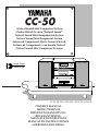
Active Servo
Technology
CC-50
Natural Sound Mini Component System
Chaîne Mini de la série “Natural Sound”
Natural Sound Mini Komponenten-System
Natural Sound Mini Komponent System
Sistema di Componenti Mini a Suono Naturale
Sistema de Componentes con Sonido Natural
Natural Sound Mini Component Systeem
OWNER‘S MANUAL
MODE D‘EMPLOI
BEDIENUNGSANLEITUNG
BRUKSANVISNING
MANUALE DI ISTRUZIONI
MANUAL DE INSTRUCCIONES
GEBRUIKSAANWIJZING
CC-50: RX-S50 + CDX-S50 + KXW-S70 + NX-S50

●
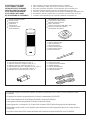
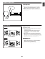
Remote control transmitter
●
Télécommande
●
Fernbedienung
●
Fjärrkontroll
●
Telecomando
●
Controlador remoto
●
Afstandbediening
●
Batteries (size AA, UM/SUM-3, R6, HP-7)
●
Piles (format AA, UM/SUM-3, R6, HP-7)
●
Batterien (Größe AA, UM/SUM-3, R6, HP-7)
●
Batterier (Storl. AA, UM/SUM-3, R6, HP-7)
●
Batterie (dimensioni AA, o UM/SUM-3, o R6, o HP-7)
●
Pilas (tamaño AA, tipo UM/SUM-3, R6, HP-7)
●
Batterijen (maat AA, UM/SUM-3, R6, HP-7)
●
AM (MW/LW) loop antenna
●
Cadre-antenne AM (PO/GO)
●
MW/LW-Rahmenantenne
●
MV/LV ramantenn
●
Antenna ad anello per AM (MW e LW)
●
Antena de cuadro AM (OM/OL)
●
AM (MW/LW) lusantenne
●
Indoor FM antenna
●
Antenne intérieure FM
●
UKW-Innenantenne
●
FM inomhusantenn
●
Antenna FM per interni
●
Antena interior de FM
●
FM binnenantenne
●
Speaker cords
●
Câbles d’enceintes
●
Lautsprecheranschlußkabel
●
Högtalarledningar
●
Cavi per gli altoparlanti
●
Cables de los altavoces
●
Luidsprekerdraden
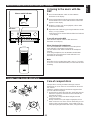
SUPPLIED ACCESSORIES
●
After unpacking, check that the following parts are contained.
ACCESSOIRES FOURNIS
●
Après le déballage, vérifier que les pièces suivantes sont incluses.
MITGELIEFERTES ZUBEHÖR
●
Nach dem Auspacken überprüfen, ob die folgenden Teile vorhanden sind.
MEDFÖLJANDE TILLBEHÖR
●
Kontrollera efter det apparaten packats upp att följande delar finns med.
ACCESSORI IN DOTAZIONE
●
Verificare che tutte le parti seguenti siano contenute nell’imballaggio dell’apparecchio.
ACCESORIOS INCLUIDOS
●
Desembale el aparato y verificar que los siguientes accesorios están en la caja.
BIJGELEVERDE ACCESSOIRES
●
Controleer na het uitpakken of de volgende onderdelen voorhanden zijn.
This product complies with the radio frequency interference requirements of the Council Directive 82/499/EEC and/or
87/308/EEC.
Cet appareil est conforme aux prescriptions de la directive communautaire 87/308/CEE.
Diese Geräte entsprechen der EG-Richtlinie 82/499/EWG und/oder 87/308/EWG.
Dette apparat overholder det gaeldende EF-direktiv vedrørende radiostøj.
Questo apparecchio è conforme al D.M.13 aprile 1989 (Direttiva CEE/87/308) sulla soppressione dei radiodisturbi.
Este producto está de acuerdo con los requisitos sobre interferencias de radio frequencia fijados por el Consejo Directivo
87/308 CEE.
Dit product voldoet aan de EEG normen betreffende radio-frekwentie storingen 82/499/EEG en/of 87/308/EEG.
-
+
12345
12345
678
67890
ABCDE
TIME
PROG
TAPE EDIT
+
I0
STOP
PLAY/PAUSE
RANDOM
REPEAT
CD
TUNER
TAPE
PRESET
DOWN UP
PLAY STOP
REC/PAUSE
SLEEPPOWER
DISPLAY
VOLUME
DECK
PHONO/AUX
TUNER DIRECT
A/B
A/B/C/D/E
PLAY
EFFECT LEVEL DSP MODE
SP/PHONES
-
+

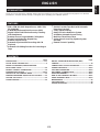
INTRODUCTION
CONTENTS
E-1
English
ENGLISH
Page
PRECAUTIONS..................................................................2-3
ACTIVE SERVO TECHNOLOGY ..........................................3
NAMES OF CONTROLS, INDICATORS AND
REAR PANEL PARTS........................................................4-6
REMOTE CONTROL TRANSMITTER................................7-9
PREPARATION FOR USE .............................................10-11
OPEN/CLOSE THE CONTROL DOOR ...............................12
TURNING THE POWER ON/OFF TO THIS SYSTEM.........12
SETTING THE CLOCK........................................................13
SOUND CONTROL..............................................................14
Page
DIGITAL SOUND FIELD PROCESSOR (DSP)
CONTROL............................................................................14
COMPACT DISC PLAYER OPERATION.......................15-22
TUNING OPERATION ....................................................23-25
TAPE DECK OPERATION ............................................26-29
RECORDING A COMPACT DISC..................................30-35
OTHER RECORDINGS...................................................36-37
HOW TO USE THE BUILT-IN TIMER.............................38-41
USING EXTERNAL UNITS.............................................42-43
MAINTENANCE...................................................................43
SPECIFICATIONS................................................................44
TROUBLESHOOTING.........................................................45
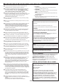
Thank you for purchasing this YAMAHA product. We hope it will give you many years of trouble-free enjoyment. For the best
performance, read this manual carefully. It will guide you in operating your YAMAHA product.
FEATURES
•
35W + 35W (6Ω) RMS Output Power, 0.08% THD,
50–20,000 Hz
•
4-Mode Digital Sound Field Processor (DSP)
•
Digital Sound Field Effective Even by Listening
with Headphones
•
Random Access Programmable CD Playback
•
Single Track/Entire Disc Repeat Play
•
Random-sequence Play
•
Automatic Synchronized Recording with CD
Playback
•
Automatic CD Editing Function for Recording to
Tape
•
Double Cassette Tape Deck with Automatic
Reversing Function
•
2-Way Speed Dubbing
•
Dolby B/C Noise Reduction System
•
40 Station Automatic Preset Tuning
•
Multi-Use Timer/Sleep Timer
•
Active Servo Processing Speaker System
(NX-S50)
•
Remote Control Capability

NOTE
Please check the copyright laws in your country to record from
records, compact discs, radio, etc. Recording of copyright material
may infringe copyright laws.
IMPORTANT
Please record the serial number of this unit in the space below.
Serial No.:
The serial number is located on the rear of the unit.
Retain this Owner’s Manual in a safe place for future reference.
WARNING
TO REDUCE THE RISK OF FIRE OR ELECTRIC SHOCK, DO
NOT EXPOSE THIS APPLIANCE TO RAIN OR MOISTURE.
CAUTION (FOR CANADA MODEL)
TO PREVENT ELECTRIC SHOCK, MATCH WIDE BLADE OF
PLUG TO WIDE SLOT AND FULLY INSERT.
FOR CANADIAN CUSTOMER
THIS DIGITAL APPARATUS DOES NOT EXCEED THE “CLASS
B” LIMITS FOR RADIO NOISE EMISSIONS FROM DIGITAL
APPARATUS SET OUT IN THE RADIO INTERFERENCE
REGULATION OF THE CANADIAN DEPARTMENT OF
COMMUNICATION.
E-2
PRECAUTIONS: READ THIS BEFORE OPERATING YOUR UNIT
•
CD pickup
Leave the power on with no disc in the unit until normal
playback is possible (about 1 hour).
•
Tape head
Leave the power on with no cassette in the unit until normal
playback is possible (about 1 hour).
Note
If condensation forms on the tape head, foreign matter may
accumulate during use.
•
Remote control
Wipe off condensation on the transmitter window with a soft
cloth before operating the unit.
CAUTION FOR CARRYING THE CD PLAYER
Be sure not to carry or tip the CD player with discs remaining in it.
■ To assure the finest performance, please read this manual
carefully. Keep it in a safe place for future reference.
■ This system is equipped with the newly developed Active Servo
Processing Speaker System. It is not designed for use with
conventional speakers. Therefore, do not attempt to connect
other speakers than the provided speaker system.
■ Choose the installation location of this unit carefully. Avoid
placing it in direct sunlight or close to a source of heat. Also avoid
locations subject to vibration and excessive dust, heat, cold or
moisture. Keep it away from sources of hum such as
transformers and electric motors.
■ Do not operate this unit upside-down. It may overheat, possibly
causing damage.
■ Never open the cabinet. If something drops into the set, contact
your dealer.
■ The openings on the cabinet assure proper ventilation of the unit.
If these openings are obstructed, the temperature inside the
cabinet will rise rapidly and eventually damage the circuits.
Therefore, avoid placing objects against these openings and do
not install the unit where the flow of air through the ventilation
openings could be impeded.
■ Always set the VOLUME control to “0” before starting the audio
source play: increase the volume gradually to an appropriate
level after the play has been started.
■ When not planning to use this unit for long periods of time (ie.,
vacation, etc.), disconnect the AC power plug from the wall outlet.
■ Grounding or polarization – Precautions should be taken so that
the grounding or polarization of an appliance is not defeated.
■ Do not use force on switches, controls or connection wires. When
moving the unit, first disconnect the power plug and the wires
connected to other equipment. Never pull the wire itself.
■ Do not attempt to clean the unit with chemical solvents; this might
damage the finish. Use a clean, dry cloth.
■ Be sure to read the “TROUBLESHOOTING” section regarding
common operating errors before concluding that the unit is faulty.
■ To prevent lightning damage, disconnect the AC power plug and
the antenna cable when there is an electrical storm.
■ Do not plug the AC power plug to the wall socket before you
finish all connections.
■ Never allow metallic items (e.g. screwdrivers, tools, etc.) to come
near the cassette deck’s record/playback head assembly in this
unit. Doing so may not only scratch or damage the head’s mirror-
smooth finish, it may change the magnetic characteristics of the
heads, causing a deterioration in reproduction performance
quality.
■ Although the cassette deck’s record/playback heads used in this
unit are high quality heads with outstanding reproduction
characteristics, they can become dirty through the use of old
tapes or from dust accumulation over time. This can have a
serious effect on reproduction quality. Clean the heads regularly
with one of the commonly available head cleaners or with
cleaning solutions.
■ The voltage to be used must be the same as that specified on
this unit. Using this product with a higher voltage than that which
is specified is dangerous and may result in a fire or other type of
accident causing damage. YAMAHA will not be held responsible
for any damage resulting from use of this unit with a voltage other
than that which is specified.
■ The sound level at a given volume setting depends on a
combination of speaker efficiency, location and many other
factors. Care should be taken to avoid exposure to sudden high
levels of sound, which may occur when turning on the unit with
the volume control setting at high, and to continuous high levels
of sound.
■ Sudden temperature changes and storage or operation in an
extremely humid environment may cause condensation inside the
cabinet.
Condensation can cause the unit to malfunction.
Follow the procedure below to eliminate condensation.
For U.K. customers
If the socket outlets in the home are not suitable for the plug
supplied with this appliance, it should be cut off and an
appropriate 3 pin plug fitted. For details, refer to the
instructions described below.
Note: The plug severed from the mains lead must be
destroyed, as a plug with bared flexible cord is hazardous if
engaged in a live socket outlet.
SPECIAL INSTRUCTIONS FOR U.K. MODEL
IMPORTANT:
The wire in the mains lead are coloured in accordance
with the following code:
Blue: NEUTRAL
Brown: LIVE
The colours of the wires in the mains lead of this
apparatus may not correspond with the coloured
markings identifying the terminals in your plug. Proceed
as follows: the wire which is coloured BLUE must be
connected to the terminal which is marked with the letter
N or coloured BLACK. The wire which is coloured
BROWN must be connected to the terminal which is
marked with the letter L or coloured RED. Making sure
that neither core is connected to the earth terminal of the
three pin plug.

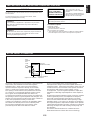
ACTIVE SERVO TECHNOLOGY
Active Servo
Processing
Amplifier
Port
Cabinet
High-
amplitude
bass
sound
Signals of low amplitude
Negative-impedance
output drive
Air woofer
(Helmholtz resonator)
Signals
E-3
English
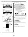
The theory of the Active Servo Technology is based upon two
major factors, the Helmholtz resonator and negative-
impedance drive. Active Servo Processing speakers
reproduce the bass frequencies through an “air woofer”,
which is a small port or opening in the speaker’s cabinet.
This opening is used instead of, and performs the functions
of, a woofer in a conventionally designed speaker system.
Thus, signals of low amplitude within the cabinet can,
according to the Helmholtz resonance theory, be output from
this opening as waves of great amplitude if the design is such
that the size of the opening and the volume of the cabinet are
in the correct proportion to satisfy a certain ratio.
In order to accomplish this, moreover, the amplitudes within
the cabinet must be both precise and of sufficient power
because these amplitudes must overcome the “load”
presented by the air that exists within the cabinet.
Thus it is this problem that is resolved through the
employment of a design in which the amplifier functions to
supply the signals. If the electrical resistance of the voice coil
is reduced to zero, the movement of the speaker unit would
become linear with respect to signal voltage, and, to
accomplish this, a special negative-impedance output-drive
amplifier for subtracting output impedance of the amplifier is
used.
By employing negative-impedance drive circuits, the amplifier
is able to generate precise, low-amplitude low-frequency
waves with superior damping characteristics, and these
waves are then radiated from the cabinet opening as high-
amplitude signals. The system can, therefore, by employing
the negative-impedance output drive amplifier and a speaker
cabinet with the Helmholtz resonator, reproduce an extremely
wide range of frequencies with amazing sound quality and
less distortion.
The features described above are combined to be the
fundamental structure of the Active Servo Technology.
CAUTION 1
Use of controls or adjustments or performance of procedures
other than those specified herein may result in hazardous
radiation exposure.
CAUTION 2
As the laser beam used in this compact disc player is harmful to
the eyes, do not attempt to disassemble the cabinet. Refer
servicing to qualified personnel only.
Laser component in this product is capable of emitting radiation
exceeding the limit for Class 1.
PRECAUTIONS: READ THIS BEFORE OPERATING YOUR UNIT
WARNING
To reduce the risk of fire or electric shock, do not expose this unit to
rain or moisture.
To avoid electrical shock, do not open the cabinet. Refer
servicing to qualified personnel only.
This compact disc player is
classified as a CLASS 1 LASER
product.
The CLASS 1 LASER PRODUCT
label is located on the rear exterior.
(Europe and U.K. model only)
Laser Diode Properties
•
Material: GaAlAs
•
Wavelength: 780nm
•
Emission Duration: continuous
•
Laser Output: max. 44.6µW*
* This output is the value measured at a distance of about 200mm
from the objective lens surface on the Optical Pick-up Block.
CLASS 1 LASER PRODUCT
APPAREIL À LASER DE CLASSE 1
PRODUCTO LASER DE CLASE 1

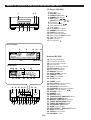
NAMES OF CONTROLS, INDICATORS AND REAR PANEL PARTS
E-4
CD Player (CDX-S50)
1. Disc Table
2. RESUME button
3. OPEN/CLOSE Button:
4. RANDOM Play Button
5. SKIP Buttons: /
(SEARCH Buttons: / )
6. Stop Button:
7. Play/Pause Button: /
8. Track Number Indicator
9. Time Display
10. (S, F) REPEAT Indicator
11. RANDOM Play Indicator
12. PROGRAM Indicator
13. Music Calendar Indicator
14. Music Calendar OVER Indicator
15. Tape Side Indicator
16. EDIT Indicator
17. Play Indicator:
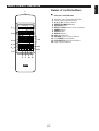
Receiver (RX-S50)
18. Effect Level Indicator
19. Phones Mode Indicator
20. Preset Number Indicator
21. Band Indicator
22. Station Frequency Indicator
23. DSP ON/OFF Indicator
24. DSP Mode Indicators
25. MEMORY Indicator
26. AUTO TUNING Indicator
27. STEREO Indicator
28. TIMER Set Indicator
29. SLEEP Indicator
30. POWER Switch
31. DSP ON/OFF Selector Button
32. Remote Control Sensor
33. DSP MODE Selector Button
34. SP/PHONES Mode Selector Button
35. INPUT Selector Buttons: /
36. VOLUME Control
37. PHONES Jack
38. DISPLAY Button
39. TUNER PRESET DOWN/UP Buttons
40. A/B/C/D/E (TIMER) Button
41. MEMORY (TIME ADJUST) Button
42. TUNING DOWN (HOUR) Button
43. TUNING UP (MINUTE) Button
44. AUTO/MAN’L (SEC) Button
45. BAND Selector Button
46. AUTO MEMORY (TIMER REC) Button
47. BASS Tone Control
48. TREBLE Tone Control
49. BALANCE Control
30 32 35 36
37
38
39
40
41
42
43
44
45
46
47
48
49
31 33 34
STEREO
AUTO TUNING
PRESET
MHz
MEMORY
SLEEP
TIMER
HALL
DISCO
CHURCH
JAZZ CLUB
DSP
ON OFF
OVER
AB
TRACK TOTAL REMAIN
RANDOM
PROG
EDIT
2 3 4 5 6 7 8 9 10 11 12 13 14 15 16 17 18 19
SF
REP
HALL
DISCO
CHURCH
JAZZ CLUB
1 20
DSP
ON OFF
8 9 10 11 12
13 16 171514
18 19 18 20 22
28 292726252423
21
For CD Player
For Receiver
1
45
2 3
6 7

E-5
English
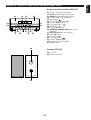
NAMES OF CONTROLS, INDICATORS AND REAR PANEL PARTS
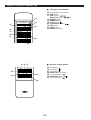
Double Cassette Tape Deck (KXW-S70)
50. DECK A Cassette Compartment
51. DECK A Select Button and Indicator
52. DECK B Select Button and Indicator
53. DECK B Cassette Compartment
54. Stop Button:
55. Play Direction Indicator ( )
56. DECK A EJECT Button
57. Fast Wind Button:
58. Play Button:
59. Reverse Mode Switch
60. DUBBING (NORMAL/HIGH) Buttons and
Indicators
61. REC/PAUSE Button and Indicator
62. Dolby NR Switch
63. Play Button:
64. Fast Wind Button:
65. DECK B EJECT Button
66. Play Direction Indicator ( )
67. PLAY Indicator
Speakers (NX-S50)
68. YST Port
69. Speaker Terminals
50 51 52 53
54
55
56
57
58
59
60 61
62
63
64
65
66
67
68
69

E-6
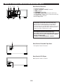
NAMES OF CONTROLS, INDICATORS AND REAR PANEL PARTS
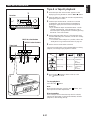
FREQUENCY STEP switch (General model only)
Because the interstation frequency spacing differs in
different areas, set the FREQUENCY STEP switch
(located at the rear) according to the frequency spacing in
your area. Before setting this switch, disconnect the AC
supply lead of this unit from the AC outlet.
Rear Panel of Receiver
1. Antenna Terminals
2. INPUT (PHONO and AUX) Terminals
3. GND Terminal
4. SPEAKERS Terminals
5. VOLTAGE SELECTOR (General model only)
6. FREQUENCY STEP Switch (General model only)
7. System Control Sockets
8. AC Supply Lead
VOLTAGE SELECTOR (General model only)
The voltage selector on the rear panel of this unit must
be set for your local main voltage BEFORE plugging
into the AC main supply.
Voltages are 110/120/220/240V AC, 50/60 Hz.
Rear Panel of Cassette Tape Deck
9. System Control Connector
Rear Panel of CD Player
10. System Control Connector
10
9
12 34 5
67 8

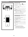
Names of control buttons
■
Receiver Control Buttons
1. Remote Control Transmitter Window
2. Preset Station Number Buttons
3. A, B, C, D, E Selector Buttons
4. PRESET DOWN/UP Buttons
5. A/B/C/D/E Button
6. EFFECT LEVEL Down (–)/Up (+) Buttons
7. POWER Switch
8. SLEEP Button
9. DISPLAY Button
10. DSP On/Off Button
11. VOLUME Down (–)/Up (+) Buttons
12. DSP MODE Selector Button
13. SP/PHONES Mode Selector Button
14. Input Selector Buttons
E-7
English
REMOTE CONTROL TRANSMITTER
-
+
12345
12345
678
67890
ABCDE
TIME
PROG
TAPE EDIT
+
I0
STOP
PLAY/PAUSE
RANDOM
REPEAT
CD
TUNER
TAPE
PRESET
DOWN UP
PLAY STOP
REC/PAUSE
SLEEPPOWER
DISPLAY
VOLUME
DECK
PHONO/AUX
TUNER DIRECT
A/B
A/B/C/D/E
PLAY
EFFECT LEVEL DSP MODE
SP/PHONES
-
+
1
2
3
4
5
6
7
8 9 10 11
14
13
12

■ CD Player Control Buttons
15. Track Number Input Buttons
16. TIME Button
17. SKIP Buttons: /
(SEARCH Buttons: / )
18. REPEAT Button
19. RANDOM Button
20. STOP Button:
21. PLAY/PAUSE Button:
22. EDIT Button
23. TAPE Button
24. PROGRAM Button
■
Tape Deck Control Buttons
25. Play Button:
26. Stop Button:
27. Play Button:
28. DECK A/B Select Button
29. Fast Wind Button:
30. REC/PAUSE Button:
31. Fast Wind Button:
E-8
REMOTE CONTROL TRANSMITTER
-
+
RANDOM
TAPE
PLAY STOP
REC/PAUSE
SLEEPPOWER
DISPLAY
VOLUME
DECK
PHONO/AUX
A/B
PLAY
EFFECT LEVEL DSP MODE
SP/PHONES
-
+
28
29
25 26 27
31
30
12345
12345
678
67890
ABCDE
TIME
PROG
TAPE EDIT
+
I0
STOP
PLAY/PAUSE
RANDOM
REPEAT
CD
TUNER
TAPE
PRESET
DOWN UP
PLAY STOP
REC/PAUSE
DECK
PHONO/AUX
TUNER DIRECT
A/B
A/B/C/D/E
PLAY
EFFECT LEVEL DSP MODE
SP/PHONES
-
+
15
16
17
18
19
24
20
23
22
21

E-9
English
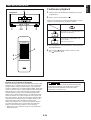
30°
30°
Remote control
sensor
0.2 m – 6 m
(8” – 20’)
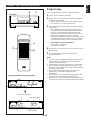
Loading the batteries for the
remote control transmitter
1 Remove the battery compartment cover.
(Press the left edge of the cover to right with a finger, and
then pull it upward.)
2 Insert 2 “AA” size batteries (UM/SUM-3, R6, HP-7 or
equivalent) into the battery compartment.
* Installing the batteries improperly may cause failure.
3 Replace the battery compartment cover.
Precautions for battery use
•
Insert the batteries according to the direction indicated in
the battery compartment.
•
Replace all batteries with new ones at the same time.
•
Remove the batteries if they are weak or if the unit is not
in use for long periods.
•
Don’t mix normal batteries with rechargeable batteries.
Proper use of the remote control
transmitter
Aim (within the range of 60° with no obstacles) the remote
control transmitter at the remote control sensor and operate
as shown.
Notes concerning use
•
Replace the batteries if control distance decreases or
operation becomes unstable.
•
Periodically clean the transmitter window on the remote
control transmitter and the sensor on the main unit with a
soft cloth.
•
Exposing the sensor on the main unit to strong light
(especially an inverter type of fluorescent lamp etc.) may
interfere with operation. In this case, reposition the main
unit to avoid direct lighting.
•
Keep the remote control transmitter away from moisture,
excessive heat, shock and vibrations.
•
The remote control transmitter’s usable range is within
0.2m (8”) and 6m (20’) away from the sensor.
REMOTE CONTROL TRANSMITTER
2
3
1

E-10
AM
ANT
GND
FM
ANT
75Ω
UNBAL.
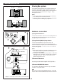
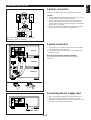
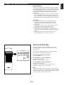
Placing the system
This system can be placed any way you like, however, be
sure not to place another unit or any object on top of the
receiver to prevent the ventilation holes on the top panel of
the receiver from being obstructed. If doing so, it may
damage the receiver.
Notes
•
If the system is put in a rack, allow a space of at least 5
cm (1-15/16”) above and behind the unit.
•
Disconnect the AC supply lead from the AC outlet before
connecting or disconnecting any component.
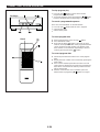
Antenna connection
(1) Supplied FM antenna
Connect the FM antenna wire to the corresponding terminal
and direct the FM antenna wire to the direction where the
strongest signal can be received.
(2) Supplied AM (MW/LW) loop antenna
Connect the AM (MW/LW) loop antenna wire to the
corresponding terminals. Position the AM (MW/LW) loop
antenna for optimum reception. Place the AM (MW/LW) loop
antenna on a shelf etc., or install it on the rack or wall with
screws (not supplied).
Notes
•
When static is still heard even after adjusting the position
of the AM (MW/LW) loop antenna, try reversing the
connection (top to bottom).
•
Do not place the AM (MW/LW) loop antenna on the unit. It
will result in noise generation, since the unit is equipped
with digital electronics. Place the AM (MW/LW) loop
antenna away from the unit.
(3) External FM antenna
Use an external FM antenna instead of an indoor FM
antenna if you need better reception. Consult your dealer.
(4) External AM (MW/LW) antenna
Use an external AM (MW/LW) antenna if you need better
reception. Consult your dealer.
Note
When using an external AM (MW/LW) antenna, be sure to
keep the wire of the AM (MW/LW) loop antenna connected.
PREPARATION FOR USE
AM
ANT
GND
FM
ANT
75Ω
UNBAL.
or
Earth rod
7.5 m (25 feet)
15 m (49 feet)
* For U.K. and Europe models, “AM” is replaced by “MW
LW”.
RX-S50 CDX-S50
KXW-S70
KXW-S70
RX-S50
CDX-S50
Placing examples
(1
(2
(3
(4

E-11
English
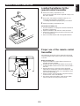
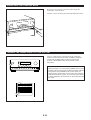
Speaker connection
Connect each speaker wire to the SPEAKERS terminals.
Cautions
•
Do not let the bare speaker wires touch each other as this
could damage the receiver and/or speakers.
•
When connecting the speakers to the unit, be sure to
connect the speaker wires properly. Do not mistake the
right channel for the left channel and the plus (+) terminal
for the minus (–) terminal.
•
Do not connect these SPEAKERS terminals to speakers
other than the provided speaker system NX-S50.
System connection
•
Connect the red connector on the rear of CDX-S50 to the
red socket on the rear of RX-S50.
•
Connect the black connector on the rear of KXW-S70 to
the black socket.
How to disconnect the system connector
Grasp both sides of the connector to disconnect the
connector.
Connecting the AC supply lead
•
After connecting the speakers and system connectors,
plug the AC supply lead into a convenient AC outlet.
•
Unplug the AC supply lead from the AC outlet if the unit is
not to be used for a long period of time.
PREPARATION FOR USE
R L
(Black wire with white line → plus (+) terminal,
black wire → minus (–) terminal)
To an
AC outlet
RX-S50
CDX-S50
KXW-S70

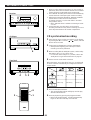
OPEN/CLOSE THE CONTROL DOOR
When it is not necessary to operate controls inside the
control door, close the door.
To open or close the door, press the right edge until it clicks.
E-12
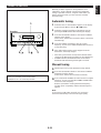
STANDBY mode
While the power is on, pressing the POWER switch (or the
POWER switch on the remote control transmitter) switches
the system to the STANDBY mode. (In this mode, the
display shows only the time.) In this mode, main voltage is
still present inside the system. If you want to switch off the
system completely, disconnect the AC power plug from the
AC outlet.
TURNING THE POWER ON/OFF TO THIS SYSTEM
If the AC supply lead is connected to the AC outlet, this
system can be turned ON and OFF (STANDBY mode) by
pressing the POWER switch on the front panel of the
receiver or the POWER button on the remote control
transmitter.
-
+
RANDOM
TAPE
PLAY STOP
REC/PAUSE
SLEEPPOWER
DISPLAY
VOLUME
DECK
PHONO/AUX
A/B
PLAY
EFFECT LEVEL DSP MODE
SP/PHONES
-
+

E-13
English
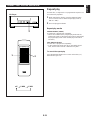
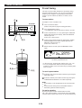
1 While the power is on, press the DISPLAY button to
display the time. If the power is off, you can proceed to the
next step.
2 While pressing the TIME ADJUST button, press the
HOUR button and set the hour.
* Press the HOUR button once to advance the time by 1
hour. Press and hold to advance continuously.
3 While pressing the TIME ADJUST button, press the
MINUTE button and set the desired time.
* Press the MINUTE button once to advance the time by
1 minute. Press and hold to advance continuously.
* The hour setting will not advance even if the minute
advance from “59” to “00”.
To display the time by “second”
While pressing the SEC button, the current time is displayed
by minute and second.
To reset the second to “00”
While pressing the SEC button, press the TIME ADJUST
button.
* If the current second is lower than 30, it is reset to 00.
* If the current second is higher than 30, the minute is
advanced by 1 minute and the second is reset to 00.
(If the current minute is “59”, in this case, the hour is also
advanced by 1 hour.)
In the event of a power failure or when the AC supply
lead is disconnected.
The time display will go out, however, the clock will function
for about 30 minutes without power supply. So you do not
have to reset the time if the AC power supply is resumed
within about 30 minutes.
When the AC power supply is resumed after more than 30
minutes pass without power supply, the time display will flash
on and off to indicate that the time must be reset.
Note
If this system is left for several minutes without setting the
time after the AC power lead of this system is connected to
the AC outlet, there may be a case that the display is turned
into a demonstration mode. (This mode is virtually
unnecessary for using this system.)
In this case, first turn the power on by pressing the POWER
switch to cancel the mode, and then set the time.
DISPLAY
MEMORY
TIME ADJ
DOWN UP
TUNING
HOUR MINUTE
MEMORY
TIME ADJ
DOWN UP
TUNING
HOUR MINUTE
SETTING THE CLOCK
Changes.
Changes.
1
2
3

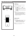
The Digital Sound Field Processor (DSP) built into this unit
presents you with the ambience of an actual concert hall,
jazz club, etc. by adding effects as sonic reflections or
reberverations that create the sound environment of a hall
etc.
This unit provides the following 4 DSP modes that simulates
actual sound environments.
E-14
DIGITAL SOUND FIELD PROCESSOR (DSP) CONTROL
VOLUME
0I0
-
+
VOLUME
SOUND CONTROL
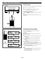
Volume
Front panel operation
Rotate the VOLUME control towards 10 to increase the
volume, and towards 0 to decrease the volume.
Remote control operation
Press the VOLUME + button to increase the volume and the
VOLUME – button to decrease the volume.
Balance
Adjust the balance of the output volume to the left and right
speakers to compensate for sound imbalance caused from
the speaker settings or the listening room condition.
Turn this clockwise to emphasize the right and
counterclockwise for the left.
Tone
BASS : Turn this clockwise to increase (or counter-
clockwise to decrease) the low frequency
response.
TREBLE : Turn this clockwise to increase (or counter-
clockwise to decrease) the high frequency
response.
BALANCE
LR
BASS TREBLE
–+–+
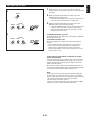
Mode
HALL
DISCO
CHURCH
JAZZ CLUB
Feature
This mode is suitable for reproducing live
recordings of pop or rock music including
vocals.
You can obtain sound expansion and
reverberations of a hall by this mode.
You can enjoy an atmosphere of disco with
lively bass and powerful sound field.
This mode creates a rich sound field of
church with long reverberations.
It is suitable for vocals etc.
This mode creates a sound field with much
presence adding spatial effect as if music
instruments are coming in front.
HALL
DISCO
CHURCH
JAZZ CLUB
MODE

E-15
English
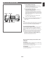
COMPACT DISC PLAYER OPERATION
DIGITAL SOUND FIELD PROCESSOR (DSP) CONTROL
Care of compact discs
Compact discs are fairly resistant to damage, however
mistracking can occur due to an accumulation of dirt on the
disc surface.
Follow the guidelines below for maximum enjoyment from
your CD collection and player.
•
Do not write on either side of the disc, particularly the non-
label side. Signals are read from the non-label side. Do
not mark this surface.
•
Keep your discs away from direct sunlight, heat and
excessive moisture.
•
Always hold the CDs by the edges. Fingerprints, dirt or
water on the CDs can cause noise or mistracking. If a CD
is dirty or does not play properly, clean it with a soft, dry
cloth, wiping straight out from the center, along the radius.
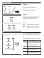
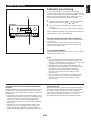
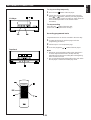
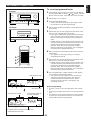
Listening to the music with the
DSP
1 Press the DSP ON/OFF switch so that “ON DSP”
illuminates on the display.
2 Select a desired DSP mode by pressing the DSP MODE
selector button once or more until the name of the mode
appears on the display.
3 Playback a source. (For source playback, refer to other
sections described later.)
4 Adjust the level of effects by pressing the EFFECT LEVEL
down (–) or up (+) button.
* Effect level can be checked with the effect level indicator
on the display.
If you will not use the DSP
Press the DSP ON/OFF switch so that “DSP OFF”
illuminates on the display.
When listening with headphones
Press the SP/PHONES mode button so that the phones
mode indicator is illuminated on the display.
You can obtain a DSP effect suitadle for the headphone
listening.
If not using headphones, the SP/PHONES mode button
should be set so that the phones mode indicator is not
illuminated on the display.
Note
DSP effect is also recorded along with a source. If you wish
to record a source without DSP effect, turn the DSP off when
recording.
Receiver
HALL
DSP
ON
-
+
12345
12345
678
67890
ABCDE
TIME
PROG
TAPE EDIT
+
I0
STOP
PLAY/PAUSE
RANDOM
REPEAT
CD
TUNER
TAPE
PRESET
DOWN UP
PLAY STOP
REC/PAUSE
SLEEPPOWER
DISPLAY
VOLUME
DECK
PHONO/AUX
TUNER DIRECT
A/B
A/B/C/D/E
PLAY
EFFECT LEVEL DSP MODE
SP/PHONES
-
+
12
4
2
1
Phones mode indicator
Receiver

E-16
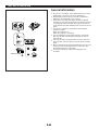
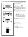
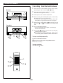
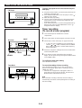
CD playback
1 Select the CD player so that “CD” appears on the display
by pressing the INPUT selector or button.
2 Press the OPEN/CLOSE button to open the disc table.
3 Place a disc on the table, label side up.
* 8 cm (3”) disc can be played without an adaptor.
4 Press the OPEN/CLOSE button to close the disc table.
* The total number of tracks and the total playing time of
the disc will be displayed for several seconds.
* The music calendar will be displayed only for the
number of tracks on the disc.
* If the compact disc contains more than 21 tracks, the
“OVER” indicator will light up on the music calendar.
5 Press the play/pause button to start playback from track 1.
* The “ ” indicator will appear and playback will begin.
As the playback of each track on the music calendar is
finished, that track number will go out.
To interrupt playback
11 Press the play/pause button.
* The “ ” indicator will flash.
22 Press the play/pause button to resume playback from the
same point.
To stop playback
Press the stop button.
To switch the unit off after use
Turn the unit off by pressing the POWER switch. (The
indicators will go off except for the current time display.)
COMPACT DISC PLAYER OPERATION
-
+
12345
12345
678
67890
ABCDE
TIME
PROG
TAPE EDIT
+
I0
STOP
PLAY/PAUSE
RANDOM
REPEAT
CD
TUNER
TAPE
PRESET
DOWN UP
PLAY STOP
REC/PAUSE
SLEEPPOWER
DISPLAY
VOLUME
DECK
PHONO/AUX
TUNER DIRECT
A/B
A/B/C/D/E
PLAY
EFFECT LEVEL DSP MODE
SP/PHONES
-
+
POWER
POWER
Total number of tracks
Music calendar Total playing time
Receiver
CD Player
1
2, 4
1
3
5, 11, 22
5, 11, 22
TRACK TOTAL
2 3 4 5 6 7 8 9 10 11 12
HALL
1
DSP
ON

E-17
English
12345
12345
678
67890
E
+
I0
TUNER DIRECT
-
+
12345
12345
678
67890
ABCDE
TIME
PROG
TAPE EDIT
+
I0
STOP
PLAY/PAUSE
RANDOM
REPEAT
CD
TUNER
TAPE
PRESET
DOWN UP
PLAY STOP
REC/PAUSE
SLEEPPOWER
DISPLAY
VOLUME
DECK
PHONO/AUX
TUNER DIRECT
A/B
A/B/C/D/E
PLAY
EFFECT LEVEL DSP MODE
SP/PHONES
-
+
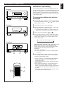
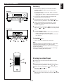
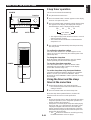
COMPACT DISC PLAYER OPERATION
Direct operation
Even when an input source other than CD player is selected,
pressing the play/pause button, a track number input button
or the RANDOM play button, or pressing the front edge of the
disc table gently will start playback directly. In this case, if
the tape deck is playing back a tape, it will be stopped
automatically.
* These ways of playback can also be used to close the disc
table. If the table is closed in these ways, playback will
begin automatically, however, the display will not show the
total number of tracks and the total playing time of the disc.
Precautions
•
If TV or radio interference occurs during CD player
operation, move the unit away from the TV or radio.
•
Subjecting the unit to shock or vibration can cause
mistracking.
•
Playing some compact discs at high volume can cause
mistracking. In this case, listen at lower volume.
•
Do not push the disc table while it is moving.
•
If the power fails while the table is open, wait until the
power supply returns or gently push the table manually to
close it.
•
The temperature range for playing compact discs is
recommended to be 5°C (41°F) – 35°C (95°F).
Direct-selection play
By using the track number input buttons on the remote
control transmitter, any track you wish to listen to can be
played directly.
Use the track number input buttons to select the desired
track number. Play will begin automatically.
A. For example, to choose selection 5
Press the “5” button.
B. For example, to choose selection 12
(1)Press the “+10” button.
(2)Within 3 seconds, press “2” button.
C. For example, to choose selection 20
(1)Press the “+10” button.
(2)Within 3 seconds, press the “+10” button again.
(3)Within 3 seconds, press the “0” button.
Note
A track number higher than the number of tracks on the disc
cannot be selected. Also, if a higher track number is selected
while the disc table is open, play will begin from the last track
on the disc when the disc table is closed.

E-18
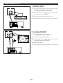
COMPACT DISC PLAYER OPERATION
-
+
12345
12345
678
67890
ABCDE
TIME
PROG
TAPE EDIT
+
I0
STOP
PLAY/PAUSE
RANDOM
REPEAT
CD
TUNER
TAPE
PRESET
DOWN UP
PLAY STOP
REC/PAUSE
SLEEPPOWER
DISPLAY
VOLUME
DECK
PHONO/AUX
TUNER DIRECT
A/B
A/B/C/D/E
PLAY
EFFECT LEVEL DSP MODE
SP/PHONES
-
+
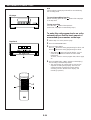
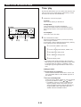
“Skip search” and “Manual search” are performed using the
same buttons.
Skip search
The beginning of any track can be found automatically.
1 Load a disc and begin playback.
2 Press the button to advance or button to
reverse through the disc.
Press once for each track to be advanced or reversed.
•
Press once to advance to the track following the
one now playing back.
•
Press once to return to the start of the track now
playing back.
•
Press twice to return to the track before the track
now playing back.
Notes
•
This function can also be performed while the unit is
stopped. Press the play/pause button when your desired
track number appears in the track number display.
Playback will begin from the beginning of the track.
•
This function will be performed forward or backward from
any point on the disc. However, it will not move forward
during playback of the final track.
Manual search
1 Begin playback.
2 Press and hold the button to advance play rapidly,
and the button to reverse play rapidly.
*
The sound can be heard (although slightly garbled)
during manual search in either direction. This is
convenient for reviewing the contents quickly.
Note
Manual search can also be performed while playback is
paused, though no sound will be heard.
CD Player
1
2
1
2
La pagina sta caricando ...
La pagina sta caricando ...
La pagina sta caricando ...
La pagina sta caricando ...
La pagina sta caricando ...
La pagina sta caricando ...
La pagina sta caricando ...
La pagina sta caricando ...
La pagina sta caricando ...
La pagina sta caricando ...
La pagina sta caricando ...
La pagina sta caricando ...
La pagina sta caricando ...
La pagina sta caricando ...
La pagina sta caricando ...
La pagina sta caricando ...
La pagina sta caricando ...
La pagina sta caricando ...
La pagina sta caricando ...
La pagina sta caricando ...
La pagina sta caricando ...
La pagina sta caricando ...
La pagina sta caricando ...
La pagina sta caricando ...
La pagina sta caricando ...
La pagina sta caricando ...
La pagina sta caricando ...
La pagina sta caricando ...
-
 1
1
-
 2
2
-
 3
3
-
 4
4
-
 5
5
-
 6
6
-
 7
7
-
 8
8
-
 9
9
-
 10
10
-
 11
11
-
 12
12
-
 13
13
-
 14
14
-
 15
15
-
 16
16
-
 17
17
-
 18
18
-
 19
19
-
 20
20
-
 21
21
-
 22
22
-
 23
23
-
 24
24
-
 25
25
-
 26
26
-
 27
27
-
 28
28
-
 29
29
-
 30
30
-
 31
31
-
 32
32
-
 33
33
-
 34
34
-
 35
35
-
 36
36
-
 37
37
-
 38
38
-
 39
39
-
 40
40
-
 41
41
-
 42
42
-
 43
43
-
 44
44
-
 45
45
-
 46
46
-
 47
47
-
 48
48


in altre lingue
- English: Yamaha CC-50 User manual
- français: Yamaha CC-50 Manuel utilisateur
- español: Yamaha CC-50 Manual de usuario
- Deutsch: Yamaha CC-50 Benutzerhandbuch
- русский: Yamaha CC-50 Руководство пользователя
- Nederlands: Yamaha CC-50 Handleiding
- português: Yamaha CC-50 Manual do usuário
- dansk: Yamaha CC-50 Brugermanual
- čeština: Yamaha CC-50 Uživatelský manuál
- polski: Yamaha CC-50 Instrukcja obsługi
- svenska: Yamaha CC-50 Användarmanual
- Türkçe: Yamaha CC-50 Kullanım kılavuzu
- suomi: Yamaha CC-50 Ohjekirja
- română: Yamaha CC-50 Manual de utilizare
Documenti correlati
-
Yamaha YST-7 Manuale del proprietario
-
-
-
-
-
-
-
-
-