
X4500 Scanner
4036-304
Lexmark and Lexmark with diamond design are
trademarks of Lexmark International, Inc., registered
in the United States and/or other countries.
• Table of Contents
• Problem Solving
• Safety and Notices
• Trademarks
• Index

Edition: March 2002
The following paragraph does not apply to any country where such provisions are inconsistent with local law:
LEXMARK INTERNATIONAL, INC. PROVIDES THIS PUBLICATION “AS IS” WITHOUT WARRANTY OF ANY KIND,
EITHER EXPRESS OR IMPLIED, INCLUDING, BUT NOT LIMITED TO, THE IMPLIED WARRANTIES OF
MERCHANTABILITY OR FITNESS FOR A PARTICULAR PURPOSE. Some states do not allow disclaimer of express or
implied warranties in certain transactions; therefore, this statement may not apply to you.
This publication could include technical inaccuracies or typographical errors. Changes are periodically made to the
information herein; these changes will be incorporated in later editions. Improvements or changes in the products or the
programs described may be made at any time.
Comments may be addressed to Lexmark International, Inc., Department D22A/032-2, 740 West New Circle Road,
Lexington, Kentucky 40550, U.S.A or e-mail at ServiceInfoAndTraining@Lexmark.com. Lexmark may use or distribute any
of the information you supply in any way it believes appropriate without incurring any obligation to you. You can purchase
additional copies of publications related to this product by calling 1-800-553-9727. In other countries, contact your point of
purchase.
Lexmark and Lexmark with diamond design are trademarks of Lexmark International, Inc., registered in the United States
and/or other countries.
Other trademarks are the property of their respective owners.
©
Copyright Lexmark International, Inc. 2002.
All rights reserved.
UNITED STATES GOVERNMENT RESTRICTED RIGHTS
This software and documentation are provided with RESTRICTED RIGHTS. Use, duplication or disclosure by the
Government is subject to restrictions as set forth in subparagraph (c)(1)(ii) of the Rights in Technical Data and Computer
Software clause at DFARS 252.227-7013 and in applicable FAR provisions: Lexmark International, Inc., Lexington, KY
40550. U.S.A.
P/N 12G9084
4036-304

iii
4036-304
Table of Contents
Safety Information . . . . . . . . . . . . . . . . . . . . . . . . . . . . . . . . . . . . . . . . . . . . . . . . . . . . . v
Safety Information . . . . . . . . . . . . . . . . . . . . . . . . . . . . . . . . . . . . . . . . . . . . . . . . . . . . v
Overview . . . . . . . . . . . . . . . . . . . . . . . . . . . . . . . . . . . . . . . . . . . . . . . . . . . . . . . . . . . . . . . . . . . . . . . . 1-1
Service Guidelines . . . . . . . . . . . . . . . . . . . . . . . . . . . . . . . . . . . . . . . . . . . . . . . . . . 1-1
Product Description . . . . . . . . . . . . . . . . . . . . . . . . . . . . . . . . . . . . . . . . . . . . . . . . . . 1-1
Ease of Use . . . . . . . . . . . . . . . . . . . . . . . . . . . . . . . . . . . . . . . . . . . . . . . . . . . . 1-1
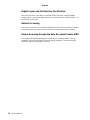
Digital Copier and Full-function Fax Machine . . . . . . . . . . . . . . . . . . . . . . . . . . 1-2
Network Scanning . . . . . . . . . . . . . . . . . . . . . . . . . . . . . . . . . . . . . . . . . . . . . . . 1-2
Duplex Scanning through the Auto Document Feeder (ADF) . . . . . . . . . . . . . . 1-2
Product Specifications . . . . . . . . . . . . . . . . . . . . . . . . . . . . . . . . . . . . . . . . . . . . . . . 1-3
Theory of Operation . . . . . . . . . . . . . . . . . . . . . . . . . . . . . . . . . . . . . . . . . . . . . . . . . 1-5
System Description . . . . . . . . . . . . . . . . . . . . . . . . . . . . . . . . . . . . . . . . . . . . . . 1-5
Mechanical Operation . . . . . . . . . . . . . . . . . . . . . . . . . . . . . . . . . . . . . . . . . . . . 1-5
Scanner Mechanism Overview and Locations . . . . . . . . . . . . . . . . . . . . . . . . . . . . . 1-7
External View . . . . . . . . . . . . . . . . . . . . . . . . . . . . . . . . . . . . . . . . . . . . . . . . . . 1-7
Internal Components . . . . . . . . . . . . . . . . . . . . . . . . . . . . . . . . . . . . . . . . . . . . . 1-8
Abbreviations . . . . . . . . . . . . . . . . . . . . . . . . . . . . . . . . . . . . . . . . . . . . . . . . . . . . . . 1-9
Problem Solving. . . . . . . . . . . . . . . . . . . . . . . . . . . . . . . . . . . . . . . . . . . . . . . . . . . . . . . . . . . . . . . . . 2-1
Error Codes . . . . . . . . . . . . . . . . . . . . . . . . . . . . . . . . . . . . . . . . . . . . . . . . . . . . . . . . 2-1
MFD Controller Errors . . . . . . . . . . . . . . . . . . . . . . . . . . . . . . . . . . . . . . . . . . . . 2-1
Scanner Errors . . . . . . . . . . . . . . . . . . . . . . . . . . . . . . . . . . . . . . . . . . . . . . . . . 2-4
Troubleshooting . . . . . . . . . . . . . . . . . . . . . . . . . . . . . . . . . . . . . . . . . . . . . . . . . . . . 2-6
Maintenance . . . . . . . . . . . . . . . . . . . . . . . . . . . . . . . . . . . . . . . . . . . . . . . . . . . . . . . . . . . . . . . . . . . . 3-1
Cleaning . . . . . . . . . . . . . . . . . . . . . . . . . . . . . . . . . . . . . . . . . . . . . . . . . . . . . . . . . . 3-1
Cover and Glass . . . . . . . . . . . . . . . . . . . . . . . . . . . . . . . . . . . . . . . . . . . . . . . . 3-1
Touch Screen . . . . . . . . . . . . . . . . . . . . . . . . . . . . . . . . . . . . . . . . . . . . . . . . . . 3-1
ADF Unit . . . . . . . . . . . . . . . . . . . . . . . . . . . . . . . . . . . . . . . . . . . . . . . . . . . . . . 3-1
Maintenance Tools . . . . . . . . . . . . . . . . . . . . . . . . . . . . . . . . . . . . . . . . . . . . . . . . . . 3-2
Removals . . . . . . . . . . . . . . . . . . . . . . . . . . . . . . . . . . . . . . . . . . . . . . . . . . . . . . . . . 3-2
Parts Replacement . . . . . . . . . . . . . . . . . . . . . . . . . . . . . . . . . . . . . . . . . . . . . . 3-2
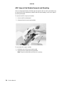
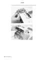
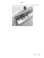
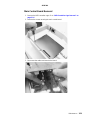
ADF Snap-in Pad Module Removal and Mounting . . . . . . . . . . . . . . . . . . . . . . 3-4
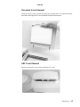
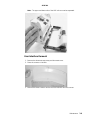
Document Cover Removal . . . . . . . . . . . . . . . . . . . . . . . . . . . . . . . . . . . . . . . . 3-5
ADF Cover Removal . . . . . . . . . . . . . . . . . . . . . . . . . . . . . . . . . . . . . . . . . . . . . 3-5
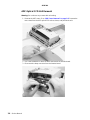
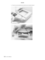
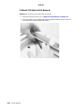
ADF Optical CCD Unit Removal . . . . . . . . . . . . . . . . . . . . . . . . . . . . . . . . . . . . 3-6
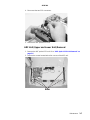
ADF Unit (Upper and Lower Unit) Removal . . . . . . . . . . . . . . . . . . . . . . . . . . . 3-7
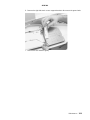
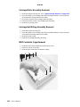
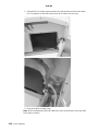
User Interface Removal . . . . . . . . . . . . . . . . . . . . . . . . . . . . . . . . . . . . . . . . . . 3-9
Upper Housing Removal . . . . . . . . . . . . . . . . . . . . . . . . . . . . . . . . . . . . . . . . . 3-12
Flatbed CCD Optical Unit Removal . . . . . . . . . . . . . . . . . . . . . . . . . . . . . . . . . 3-14
Carriage Motor Assembly Removal . . . . . . . . . . . . . . . . . . . . . . . . . . . . . . . . 3-16
Carriage Belt Pulley Assembly Removal . . . . . . . . . . . . . . . . . . . . . . . . . . . . . 3-16
MFD Controller Cage Removal . . . . . . . . . . . . . . . . . . . . . . . . . . . . . . . . . . . . 3-16
Product Features . . . . . . . . . . . . . . . . . . . . . . . . . . . . . . . . . . . . . . . . . . . . . . . . . . . 1-1

iv
4036-304
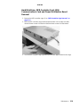
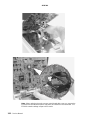
Hard Disk Drive, MFD Controller Card, 1394 Communications Card and Power
Distribution Board Removal . . . . . . . . . . . . . . . . . . . . . . . . . . . . . . . . . . . . . . . 3-19
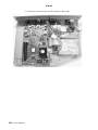
Main Control Board Removal . . . . . . . . . . . . . . . . . . . . . . . . . . . . . . . . . . . . . 3-21
Connector Locations . . . . . . . . . . . . . . . . . . . . . . . . . . . . . . . . . . . . . . . . . . . . . . . . . . . . . . . . . . . . 4-1
Main Scanner Board . . . . . . . . . . . . . . . . . . . . . . . . . . . . . . . . . . . . . . . . . . . . . 4-1
MFD Controller Cage . . . . . . . . . . . . . . . . . . . . . . . . . . . . . . . . . . . . . . . . . . . . . 4-2
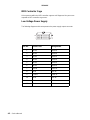
Low Voltage Power Supply . . . . . . . . . . . . . . . . . . . . . . . . . . . . . . . . . . . . . . . . 4-2
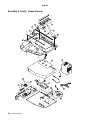
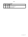
Parts Catalog. . . . . . . . . . . . . . . . . . . . . . . . . . . . . . . . . . . . . . . . . . . . . . . . . . . . . . . . . . . . . . . . . . . . 5-1
Index . . . . . . . . . . . . . . . . . . . . . . . . . . . . . . . . . . . . . . . . . . . . . . . . . . . . . . . . . . . . . . . .I-1

Safety Information v
4036-304
Safety Information
Safety Information
• This product is designed, tested and approved to meet strict global safety standards
with the use of specific Lexmark components. The safety features of some parts may
not always be obvious. Lexmark is not responsible for the use of other replacement
parts.
• The maintenance information for this product has been prepared for use by a
professional service person and is not intended to be used by others.
• There may be an increased risk of electric shock and personal injury during
disassembly and servicing of this product. Professional service personnel should
understand this and take necessary precautions.
Consignes de Sécurité
• Ce produit a été conçu, testé et approuvé pour respecter les normes strictes de
sécurité globale lors de l'utilisation de composants Lexmark spécifiques. Les
caractéristiques de sécurité de certains éléments ne sont pas toujours évidentes.
Lexmark ne peut être tenu responsable de l'utilisation d'autres pièces de rechange.
• Les consignes d'entretien et de réparation de ce produit s'adressent uniquement à
un personnel de maintenance qualifié.
• Le démontage et l'entretien de ce produit pouvant présenter certains risques
électriques, le personnel d'entretien qualifié devra prendre toutes les précautions
nécessaires.
Norme di sicurezza
• Il prodotto è stato progettato, testato e approvato in conformità a severi standard di
sicurezza e per l’utilizzo con componenti Lexmark specifici. Le caratteristiche di
sicurezza di alcune parti non sempre sono di immediata comprensione. Lexmark
non è responsabile per l’utilizzo di parti di ricambio di altri produttori.
• Le informazioni riguardanti la manutenzione di questo prodotto sono indirizzate
soltanto al personale di assistenza autorizzato.
• Durante lo smontaggio e la manutenzione di questo prodotto, il rischio di subire
scosse elettriche e danni alla persona è più elevato. Il personale di assistenza
autorizzato, deve, quindi, adottare le precauzioni necessarie.

vi Service Manual
4036-304
Sicherheitshinweise
• Dieses Produkt und die zugehörigen Komponenten wurden entworfen und getestet,
um beim Einsatz die weltweit gültigen Sicherheitsanforderungen zu erfüllen. Die
sicherheitsrelevanten Funktionen der Bauteile und Optionen sind nicht immer
offensichtlich. Sofern Teile eingesetzt werden, die nicht von Lexmark sind, wird von
Lexmark keinerlei Verantwortung oder Haftung für dieses Produkt übernommen.
• Die Wartungsinformationen für dieses Produkt sind ausschließlich für die
Verwendung durch einen Wartungsfachmann bestimmt.
• Während des Auseinandernehmens und der Wartung des Geräts besteht ein
zusätzliches Risiko eines elektrischen Schlags und körperlicher Verletzung. Das
zuständige Fachpersonal sollte entsprechende Vorsichtsmaßnahmen treffen.
Pautas de Seguridad
• Este producto se ha diseñado, verificado y aprobado para cumplir los más estrictos
estándares de seguridad global usando los componentes específicos de Lexmark.
Puede que las características de seguridad de algunas piezas no sean siempre
evidentes. Lexmark no se hace responsable del uso de otras piezas de recambio.
• La información sobre el mantenimiento de este producto está dirigida
exclusivamente al personal cualificado de mantenimiento.
• Existe mayor riesgo de descarga eléctrica y de daños personales durante el
desmontaje y la reparación de la máquina. El personal cualificado debe ser
consciente de este peligro y tomar las precauciones necesarias.
Informações de Segurança
• Este produto foi concebido, testado e aprovado para satisfazer os padrões globais
de segurança na utilização de componentes específicos da Lexmark. As funções de
segurança de alguns dos componentes podem não ser sempre óbvias. A Lexmark
não é responsável pela utilização de outros componentes de substituição.
• As informações de segurança relativas a este produto destinam-se a profissionais
destes serviços e não devem ser utilizadas por outras pessoas.
• Risco de choques eléctricos e ferimentos graves durante a desmontagem e
manutenção deste produto. Os profissionais destes serviços devem estar avisados
deste facto e tomar os cuidados necessários.

Safety Information vii
4036-304
Informació de Seguretat
• Aquest producte està dissenyat, comprovat i aprovat per tal d'acomplir les estrictes
normes de seguretat globals amb la utililització de components específics de
Lexmark. Les característiques de seguretat d'algunes peces pot ser que no sempre
siguin òbvies. Lexmark no es responsabilitza de l'us d'altres peces de recanvi.
• La informació pel manteniment d’aquest producte està orientada exclusivament a
professionals i no està destinada a ningú que no ho sigui.
• El risc de xoc elèctric i de danys personals pot augmentar durant el procés de
desmuntatge i de servei d’aquest producte. El personal professional ha d’estar-ne
assabentat i prendre les mesures convenients.

viii Service Manual
4036-304

Overview 1-1
4036-304
1. Overview
This manual is for maintenance engineers. It describes the maintenance areas,
installation, disassembly, and the main troubleshooting guides.
Take your time to read this manual thoroughly to obtain comprehensive knowledge about
the scanner before servicing the unit.
Service Guidelines
1. Before disassembling the scanner, make sure the power supply cord is disconnected
from the power outlet. Do not remove or install the connectors on the scanner with
the power supply turned ON.
2. Use caution not to drop small parts or screws inside the unit when disassembling
and reassembling.
3. Do not pull the connector cable when disconnecting it. Hold the connector.
4. When carrying the scanning head unit, put it in an anti-static bag.
5. Keep the document glass platen surface clean with a dry clean lint free cloth.
Product Description
The 4036-304 Scanner is a multifunction solution that offers integrated print, copy, fax
and color network-scanning capabilities for increased small workgroup productivity. The
scanner is easy to use and provides low-cost access to key office functions, including fax
from workstation, network color copying, scanning, and electronic document routing.
Give your document to the scanner, and in a few steps, it scans to the network and
delivers it wherever, to whomever you want. With this scanner, inefficient trips to the
mailroom, copier, fax machine and to your workstation are a thing of the past.
Product Features
Ease of Use
The user interface on the front of the scanner looks like a panel on a copier with standard
phone keys added. The operating steps follow the same procedure as that of a copier or
fax machine.

1-2 Service Manual
4036-304
Digital Copier and Full-function Fax Machine
When the scanner is connected to a Lexmark printer, it performs convenient digital
copying. When connected to telephone line, the scanner performs a full fax function - to
send and to receive faxes.
Network Scanning
The scanner uses two Color Charge-Coupled Devices (CCD) when scanning. Through a
network port at the rear of the scanner, the product is able to do network scanning.
Duplex Scanning through the Auto Document Feeder (ADF)
To increase workgroup productivity, the scanner uses the advance duplex scanning
capability. The scan speed limit is 20 ppm at 300 dpi resolution. The auto document
feeder can hold up to 50 pages at one time.

Overview 1-3
4036-304
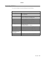
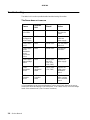
Product Specifications
The scanner is designed to meet the following product specifications:
Scanner
Scanner Type Flatbed Scanner with ADF built in
Optical Resolution Flatbed: 300x600 dpi
ADF: 300x300 dpi
Enhanced Resolution 9600x9600 dpi
Scan Speed 10 ppm at 300 dpi color for single page scanning
20 ppm at 300 dpi line-art, duplex for ADF
Scan Method Color Charge-Coupled Device (CCD)
Light Source Cold Cathode Fluorescent Lamp (CCFL)
CPU Arm 7 KS32C41000
Scan Area Max. 8.5 x 14.0 inch (legal size) for ADF
Display 640x480 color VGA touch screen
Image Types 42-bit color (internal)
14-bit gray (internal)
1-bit line-art, Dither, Error Diffusion
Scan Accuracy Flatbed ADF
1. Leading Edge <-1 ~ +2 mm <2.5 ~ +2.5 mm
2. Side Edge <-1 ~ +2 mm <2.5 ~ +2.5 mm
3. Skew <1 mm <2 mm
4. Magnification Rate
Tolerance (Horizontal
and Vertical)
-1.5% ~ +1.5% -1.5% ~ +1.5%
Physical Dimension Width: 570 mm Depth: 430 mm Height: 315 mm
Weight 14 kg

1-4 Service Manual
4036-304
Environment:
-Operating
-Storage
10°C to 35°C (50°F to 95°F)
20% to 80% RH (Relative Humidity)
-40°C to 65°C (-40°F to 149°F)
10% to 90% RH (Relative Humidity)
Random Vibration:
-Unpacked non-op
-Package
-Bump
-Drop
10-200Hz, 0.005 p.s.d. (G^2/Hz)
5-200Hz, 0.015 p.s.d. -6 dB/oct
One hour in 3 major axes
Severity: 25g/6ms, 1000 times in each direction
Must meet NSTA specification
Drop Point: 1 corner, 3 edges and 6 surfaces
Total 10 times
Acoustic Noise Operating: 58 dB or less
Electrostatic Discharge EC 1000-4-2 ESD Standard
Safety Regulation UL, CSA, TUV/GS, SEMKO
EMC regulation FCC Part 15 Subchapter J Class A
CE Marking, C-Tick
ADF
General Specifications:
-Optical Resolution
-Document Capacity
300x300 dpi
50 sheets
Document:
-Document Size
-Thickness
Max. 8.5 x 14 inch (W x L)
Min. 4.5 x 5.5 inch (W x L)
0.05~0.15 mm

Overview 1-5
4036-304
Theory of Operation
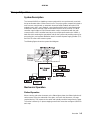
System Description
The Lexmark X4500 is a duplexing scanner option which can synchronously scan both
the top and bottom sides of a document in color. The major system components include a
main scanner control board, an automatic document feeder, flatbed, two optical CCD
modules (one in ADF, one in flatbed), a user interface with a touch screen panel and a
multifunction device controller cage located within the base of the scanner. The MFD
controller cage includes a 1394 communications card to communicate with the main
scanner board, a MFD controller board to process all jobs performed on the X4500, a
hard disk drive containing the operational code for the system and providing memory for
processing jobs, and a power distribution board. An external power supply provides 5, 12,
and 24 V dc to the entire scanner system.
The following figure shows the system block diagram.
Mechanical Operation
Flatbed Operation
When scanning, place the document on the flatbed glass platen, the flatbed optical unit/
carrier moves across the underside of the glass, and scans the document. A charge-
coupled device (CCD) mounts to the carrier and optically reads the image from the page.
The carrier is driven by a 2-phase stepping motor which moves the carriage at 1/300 inch
each step.

1-6 Service Manual
4036-304
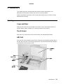
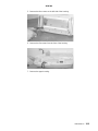
Auto Document Feeder Operation
When using the Auto Document Feeder (ADF) mechanism, a page is fed into the ADF by
a pick roller and through the ADF by a feed roller. A separation pad located opposite to
the pick roller is used to properly feed the pages one at a time when placed on the input
tray. The flatbed optical unit/carrier is positioned to the far left so when the paper passes
through the ADF, the bottom side of the page is scanned by the flatbed CCD. The home
position sensor detects when the carrier is in the proper position for ADF scanning. In
addition, an ADF cover open sensor detects when the upper ADF assembly is open or
closed into proper operating position. The scanner cannot operate when this sensor is
open.
While the page is fed through and scanned from the bottom via the flatbed CCD, the top
side of the page is simultaneously scanned via a CCD unit positioned within the ADF unit.
As the page feeds between the two CCD units, the page discharges to the exit tray on the
left side of the ADF.

Overview 1-7
4036-304
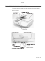
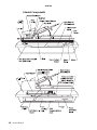
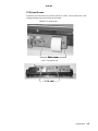
Scanner Mechanism Overview and Locations
This section contains an overview of the major components of the scanner hardware.
External View

1-8 Service Manual
4036-304
Internal Components

Overview 1-9
4036-304
Abbreviations
ADF Auto Document Feeder
CCD Charge-Couple Device
CCFL Cold Cathode Fluorescent Lamp
CDB Command Descriptor Blocks
DMM Digital Multimeter
LED Light Emitting Diode
MFD Multi Function Device
PCBA Printed Circuit Board Assembly
UI User Interface

1-10 Service Manual
4036-304

Problem Solving 2-1
4036-304
2. Problem Solving
This chapter describes two methods to solve the operational problems. The first relies on
the scanner internal diagnostics to report error codes. The second uses troubleshooting
techniques to isolate the problem. In many cases, the internal error codes will help you to
locate the source of the problem quickly. If no error codes are reported, or if the error
codes do not locate the source of the problem, refer to the troubleshooting section.
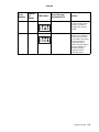
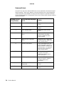
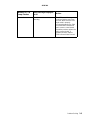
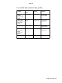
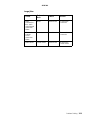
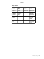
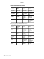
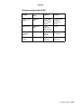
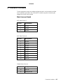
Error Codes
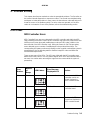
MFD Controller Errors
MFD Controller Errors are errors detected by the MFD controller card within the MFD
cage pertaining to electronic cards. All MFD controller cage errors are posted to the user
interface touch screen along with audible beep codes and LED codes (visible on the
lower left side of the MFD controller card). During the Power-On Self Test procedure,
errors detected cause a number of audible beeps to be produced three times. The
corresponding LED pattern continuously displays on the controller card until the system is
powered down. Use the following tables to read the beep/LED codes and follow the
recommended repair action.
There are two rows of four LEDs. The LEDs are visible with the MFD controller cage
detached from the scanner. The LED pattern depicts which LEDs are illuminated in the
two rows. Use caution when removing the cage from the scanner while the system is
powered up.
Error
Number
Number
of
Beeps
LED Pattern
Error Message
Displayed to UI
Action
21 2 Modem not found Modem on the MFD
controller card is not
found. Replace the
MFD controller board.
22 2 PCI Bus failure Replace the MFD
controller board.
24 2 Serial Port failure Problem with TTY/
Serial Port. Replace the
MFD controller board.

2-2 Service Manual
4036-304
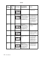
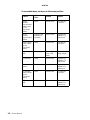
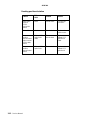
28 2 Problem with the CPU Replace the MFD
controller board.
31 3 (No Hard Drive Found)
Note: Error code
message not displayed
on the user interface.
Only beep code and
LED patterns are
generated for this error.
Check connections to
the hard disk drive and
associated cables for
continuity. Check power
going to the hard disk
drive. Replace the
power distribution card
if no power is present. If
power is present,
replace the hard disk
drive.
32 3 (Missing OS)
Note: Error code
message not displayed
on the user interface.
Only beep code and
LED patterns are
generated for this error.
The OS is not found.
Replace or reformat the
hard drive.
34 3 Hard Drive failure There was an error
writing to the hard drive
or the OS is corrupt.
Replace or reformat the
hard disk drive.
41 4 Scanner Interface not
found
The scanner image
processing board was
not found. Check
connections to the
interface board. If
connections are good,
replace the 1394
communications board.
51 5 (No Memory)
Note: Error code
message not displayed
on the user interface.
Only beep code and
LED patterns are
generated for this error.
The memory DIMM was
not detected or not
functioning. Replace
the memory DIMM.
Error
Number
Number
of
Beeps
LED Pattern
Error Message
Displayed to UI
Action
La pagina si sta caricando...
La pagina si sta caricando...
La pagina si sta caricando...
La pagina si sta caricando...
La pagina si sta caricando...
La pagina si sta caricando...
La pagina si sta caricando...
La pagina si sta caricando...
La pagina si sta caricando...
La pagina si sta caricando...
La pagina si sta caricando...
La pagina si sta caricando...
La pagina si sta caricando...
La pagina si sta caricando...
La pagina si sta caricando...
La pagina si sta caricando...
La pagina si sta caricando...
La pagina si sta caricando...
La pagina si sta caricando...
La pagina si sta caricando...
La pagina si sta caricando...
La pagina si sta caricando...
La pagina si sta caricando...
La pagina si sta caricando...
La pagina si sta caricando...
La pagina si sta caricando...
La pagina si sta caricando...
La pagina si sta caricando...
La pagina si sta caricando...
La pagina si sta caricando...
La pagina si sta caricando...
La pagina si sta caricando...
La pagina si sta caricando...
La pagina si sta caricando...
La pagina si sta caricando...
La pagina si sta caricando...
La pagina si sta caricando...
La pagina si sta caricando...
La pagina si sta caricando...
La pagina si sta caricando...
La pagina si sta caricando...
La pagina si sta caricando...
La pagina si sta caricando...
La pagina si sta caricando...
La pagina si sta caricando...
La pagina si sta caricando...
La pagina si sta caricando...
La pagina si sta caricando...
-
 1
1
-
 2
2
-
 3
3
-
 4
4
-
 5
5
-
 6
6
-
 7
7
-
 8
8
-
 9
9
-
 10
10
-
 11
11
-
 12
12
-
 13
13
-
 14
14
-
 15
15
-
 16
16
-
 17
17
-
 18
18
-
 19
19
-
 20
20
-
 21
21
-
 22
22
-
 23
23
-
 24
24
-
 25
25
-
 26
26
-
 27
27
-
 28
28
-
 29
29
-
 30
30
-
 31
31
-
 32
32
-
 33
33
-
 34
34
-
 35
35
-
 36
36
-
 37
37
-
 38
38
-
 39
39
-
 40
40
-
 41
41
-
 42
42
-
 43
43
-
 44
44
-
 45
45
-
 46
46
-
 47
47
-
 48
48
-
 49
49
-
 50
50
-
 51
51
-
 52
52
-
 53
53
-
 54
54
-
 55
55
-
 56
56
-
 57
57
-
 58
58
-
 59
59
-
 60
60
-
 61
61
-
 62
62
-
 63
63
-
 64
64
-
 65
65
-
 66
66
-
 67
67
-
 68
68


in altre lingue
- English: Lexmark X4500 User manual
Documenti correlati
-
Lexmark X7500 Manuale utente
-
Lexmark 4600 Series Manuale utente
-
-
Lexmark 6500E Manuale utente
-
-
Lexmark X340 Manuale utente
-
Lexmark X422 Manuale utente
-
-
-
Lexmark X500n MFP 7100-XXX Manuale utente