A
Hardware Review
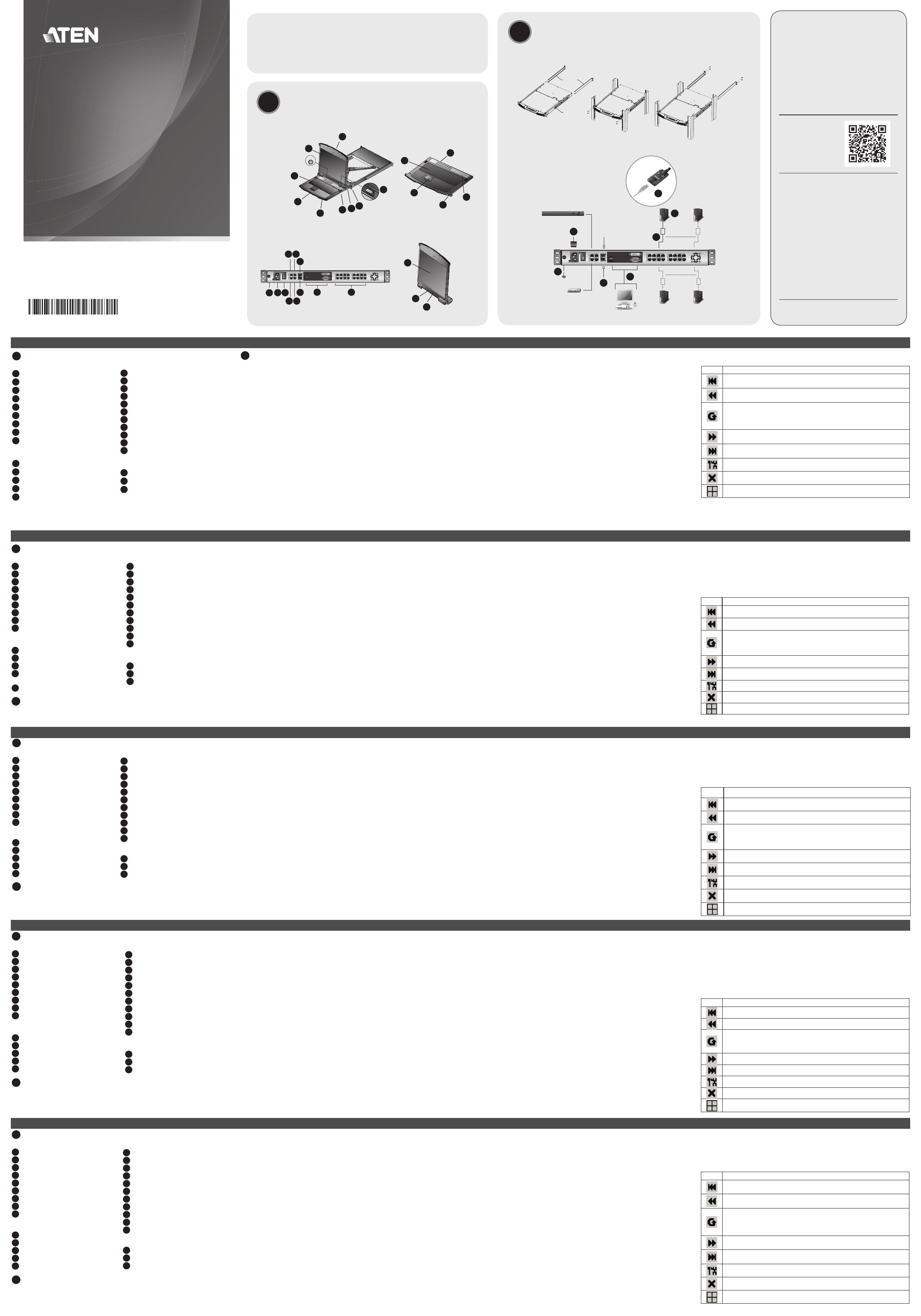
Front View
1
Upper Handle
2
LCD Module
3
Keyboard Module
4
Lower Handle
5
Power LED
6
Keyboard Release Catch
7
LCD Release Catch
Rack Mounting Tabs
9
LED Illumination Light
Keyboard Module
1
Keyboard
2
Touchpad
3
External Mouse Port
4
Lock LEDs & Reset Switch
5
Port Selection Buttons and LEDs
B
Hardware Installation
Rack Mounting
1. While one person positions the switch in the rack and holds it in place, the
second person—using the screws provided with the rack mounting kit— loosely
screws the front brackets to the rack.
2. While the fi rst person still holds the switch in place, the second person slides
the L brackets into the switch's side mounting brackets, from the rear until the
bracket fl anges contact the rack, then—using the screws provided with the rack
mounting kit—screws the L brackets to the rack.
3. After the L brackets have been secured, tighten the front bracket screws.
Note: 1. Cage nuts are provided for racks that are not pre-threaded.
2. Allow at least 5.1 cm on each side for proper ventilation, and at least
12.7 cm at the back for the power cord and cable clearance.
Single Station Installation
1. Use the grounding wire to connect the switch’s grounding terminal to a suitable
grounded object.
2. Plug your Local Console’s keyboard, monitor (DVI-D, or VGA), and mouse into the
unit’s Console Ports. Each port is color coded and marked with an appropriate icon.
3. Use Cat 5e cable to connect any available KVM port to a KVM Adapter Cable.
4. Connect the KVM Adapters to the servers.
5. Plug a cable from the LAN into the KL1108VN / KL1116VN’s primary LAN port or
secondary LAN port.
6. Plug the power cord. After the installation is complete, you can turn on the
KL1108VN / KL1116VN’s power. After it is powered on, you can turn on the
servers.
Operation
KL1108VN / KL1116VN installations provide two methods to obtain instant access
to any computer on the installation: Manual and the Port Toolbar.
Manual
For manual port selection, simply press the Port Selection button on the keyboard
that corresponds to the device you want to access.
The Port Toolbar
The KVM over IP switch’s interface provides a toolbar to help you with port
switching operations from within the captured port. To bring up the toolbar, tap the
GUI Hotkey (Scroll Lock or Ctrl), twice. The toolbar appears at the upper left corner
of the screen: When the toolbar displays mouse and keyboard input has no effect
on the server connected to the port. To carry out operations on the server, close the
toolbar by clicking its X icon. To return to the Port Access Connections page, either
click the appropriate icon (see The Toolbar Icons), or tap the GUI hotkey again.
Toolbar Hotkey Port Switching
When the toolbar displays, you can use hotkeys to provide KVM focus to a port
directly from the keyboard. The KVM over IP switch provides the following hotkey
features:
• Going directly to a port by keying in its port number and clicking Enter.
• Auto Scanning
• Skip Mode Switching
The hotkeys are: A and P for Auto Scanning; and the Arrow Keys for Skip
Mode.
© Copyright 2017 ATEN
®
International Co., Ltd.
ATEN and the ATEN logo are trademarks of ATEN International Co., Ltd. All rights reserved. All
other trademarks are the property of their respective owners.
This product is RoHS compliant.
Part No. PAPE-1223-G70G Printing Date: 01/2017
8/16-Port Cat 5 Dual Rail LCD KVM over IP Switch
Quick Start Guide
KL1108VN / KL1116VN
KL1108VN / KL1116VN Cat 5 Dual Rail LCD KVM over IP Switch
www.aten.com
Commutateur KVM via IP double rail LCD Cat 5 KL1108VN / KL1116VN
www.aten.com
Cat-5-Dualschienen-LCD-KVM-over-IP-Switch KL1108VN / KL1116VN
www.aten.com
KVM LCD de Doble Rail Cat 5 sobre Conmutador IP KL1108VN / KL1116VN
www.aten.com
Switch KVM over IP KL1108VN / KL1116VN Cat 5 Dual Rail LCD
www.aten.com
Rear View
1
Grounding Terminal
2
Power Socket
3
Power Switch
4
PON Port
5
Serial 2 Port (Secondary)
6
LAN 2 Port (Secondary)
7
Modem Port
8
Serial 1 Port (Primary)
9
LAN 1 Port (Primary)
10
Local Console Ports
11
KVM Ports
LCD Module
1
LCD Display
2
LCD Controls
3
LCD On/Off Button
Package Contents
1 KL1108VN / KL1116VN Cat 5 Dual Rail LCD KVM over IP Switch
2 SA0142 Serial Adapters (RJ45-F to DB9-M; DTE to DCE)
1 Power Cord
1 Mounting kit
1 User Instructions
Support and Documentation Notice
All information, documentation, fi rmware,
software utilities, and specifi cations
contained in this package are subject to
change without prior notifi cation by the
manufacturer.
To reduce the environmental impact of our
products, ATEN documentation and software
can be found online at
http://www.aten.com/download/
Technical Support
www.aten.com/support
이 기기는 업무용(A급) 전자파적합기기로서 판매자 또는
사용자는 이 점을 주의하시기 바라며, 가정외의 지역에
서 사용하는 것을 목적으로 합니다.
Scan for
more information
B
Hardware Installation
L Brackets
Side Mounting
Bracket (Typ.)
Rack mounting
Single Station Installation
6
5
4
3
1
2
3
PDU
Modem
1
1
1
2
2
3
2
3
3
4
5
4
6
7
8
9
5
2 3
4 5
7
1
8
9
6
1110
Press the Exit/Light pushbutton
for two seconds to turn the
LED light ON or Off. (Default: On)
EXIT I LIGHT
Front View
LCD Module
Keyboard Module
Rear View
A
Hardware Review
The Toolbar Icons
The meanings of the toolbar icons are explained in the table below.
Icon Purpose
Click to skip to the fi rst accessible port on the entire installation, without having
to recall the Port Access page.
Click to skip to the fi rst accessible port previous to the current one, without
having to recall the Port Access page.
Click to begin Auto Scan Mode. The KVM over IP switch automatically switches
among the ports that were selected for Auto Scanning with the Filter function.
This allows you to monitor their activity without having to switch among them
manually.
Click to skip from the current port to the next accessible one, without having to
recall the Port Access page.
Click to skip from the current port to the last accessible port on the entire
installation, without having to recall the Port Access page.
Click to recall the Port Access page.
Click to close the toolbar.
Click to invoke Panel Array Mode
EMC Information
FEDERAL COMMUNICATIONS COMMISSION INTERFERENCE
STATEMENT:
This equipment has been tested and found to comply with the limits
for a Class A digital device, pursuant to Part 15 of the FCC Rules.
These limits are designed to provide reasonable protection against
harmful interference when the equipment is operated in a commercial
environment. This equipment generates, uses, and can radiate radio
frequency energy and, if not installed and used in accordance with
the instruction manual, may cause harmful interference to radio
communications. Operation of this equipment in a residential area
is likely to cause harmful interference in which case the user will be
required to correct the interference at his own expense.
FCC Caution: Any changes or modifi cations not expressly approved by
the party responsible for compliance could void the user's authority to
operate this equipment.
Warning: This equipment is compliant with Class A of CISPR 32. In a
residential environment this equipment may cause radio interference.
Suggestion: Shielded twisted pair (STP) cables must be used with the
unit to ensure compliance with FCC & CE standards.
This device complies with Part 15 of the FCC Rules. Operation is subject
to the following two conditions:(1) this device mat not cause harmful
interference, and(2) this device must accept any interference received,
including interference that may cause undesired operation.
A
Hardwareübersicht
Ansicht von vorne
1
Oberer Griff
2
LCD-Modul
3
Tastaturmodul
4
Unterer Griff
5
Betriebsanzeige-LED
6
Tastaturfreigaberiegel
7
LCD-Freigaberiegel
8
Rackmontageverschlüsse
9
LED-Beleuchtung
Tastaturmodul
1
Tastatur
2
Touchpad
3
Anschluss für externe Maus
4
Sperr-LEDs und Reset-Schalter
5
Portauswahltasten und -LEDs
B
Hardwareinstallation
Rackmontage
1. Während eine Person den Switch im Rack ausrichtet und festhält, verschraubt
die zweite Person die vordere Halterung mit den im Rackmontageset enthaltenen
Schrauben locker mit dem Rack.
Ansicht von hinten
1
Erdungsklemme
2
Netzanschluss
3
Netzschalter
4
PON-Port
5
Seriell-2-Port (sekundär)
6
LAN-2-Port (sekundär)
7
Modemanschluss
8
Seriell-1-Port (primär)
9
LAN-1-Port (primär)
10
Lokale Konsolenanschlüsse
11
KVM-Ports
LCD-Modul
1
LC-Display
2
LCD-Bedienelemente
3
LCD-ein/aus-Taste
2. Während die erste Person den Switch weiterhin festhält, schiebt die zweite
Person die L-Halterungen von hinten in die seitlichen Montagehalterungen des
Switch, bis die Halterungsfl ansche das Rack berühren. Dann schraubt sie die
L-Halterungen mit den im Rackmontageset enthaltenen Schrauben an das Rack.
3. Ziehen Sie nach Befestigung der L-Halterungen die Schrauben der vorderen
Halterung fest.
Hinweis: 1. Käfi gmuttern werden für Racks ohne vorbereitete
Gewindebohrungen bereitgestellt.
2. Lassen Sie zur angemessenen Belüftung an beiden Seiten einen
Abstand von mindestens 5,1 cm. An der Rückseite müssen Sie für
Netz- und andere Kabel einen Freiraum von mindestens 12,7 cm
einhalten.
Einzelne Station installieren
1. Verbinden Sie die Erdungsklemme des Switch über ein Erdungskabel mit einem
geeigneten geerdeten Objekt.
2. Schließen Sie Tastatur, Monitor (DVI-D oder VGA) und Maus Ihrer lokalen Konsole
an die Konsolenanschlüsse des Gerätes an. Jeder Anschluss ist farbig codiert und
mit einem geeigneten Symbol gekennzeichnet.
3. Verbinden Sie jeden verfügbaren KVM-Port über ein Cat-5e-Kabel mit einem
KVM-Adapterkabel.
4. Verbinden Sie die KVM-Adapter mit den Servern.
5. Schließen Sie ein Kabel vom LAN am primären oder sekundären LAN-Port des
KL1108VN / KL1116VN an.
6. Schließen Sie das Netzkabel an. Nach Abschluss der Installation können Sie den
KL1108VN / KL1116VN einschalten. Sobald er hochgefahren ist, können Sie die
Server einschalten.
Bedienung
KL1108VN und KL1116VN bieten zwei Möglichkeiten, sofortigen Zugriff auf jeden
Computer in der Installation zu erhalten: Manuell und per Portwerkzeugleiste.
Manuell
Bei der manuellen Portauswahl drücken Sie einfach die dem Zielgerät entsprechende
Portauswahltaste an der Tastatur.
Portwerkzeugleiste
Die Benutzeroberfl äche des KVM-over-IP-Switch bietet eine Werkzeugleiste, über
die Sie zwischen den Ports wechseln können. Drücken Sie zum Einblenden der
Werkzeugleiste zweimal die Schnelltaste (Rollen-Taste oder Strg). Die Werkzeugleiste
wird unten links am Bildschirm angezeigt: Während die Werkzeugleiste anzeigt
wird, hat die Maus- und Tastatureingabe keinen Einfl uss auf den mit dem Port
verbundenen Server. Schließen Sie die Werkzeugleiste durch Anklicken des
X-Symbols, damit die Vorgänge am Server ausgeführt werden. Sie können zur
Portzugriffsseite zurückkehren, indem Sie das entsprechende Symbol anklicken (siehe
„Symbole der Werkzeugleiste“) oder erneut die Schnelltaste drücken.
Portwechsel über Tastenkombination der Werkzeugleiste
Wenn die Werkzeugleiste angezeigt wird, können Sie den KVM-Fokus mit
Tastenkombinationen direkt über die Tastaturauf einen bestimmten Port richten. Der
KVM-over-IP-Switch unterstützt folgendeTastenkombinationen:
• Direkter Wechsel zu einem Port durch Eingabe seiner Portnummer und Betätigen
der Enter-Taste.
• Automatische Suche
• Wechselmodus
Die Tastenkombinationen sind: A und P für automatische Suche; Pfeiltasten
fürWechselmodus.
Symbole der Werkzeugleiste
Die Bedeutungen der Symbole in der Werkzeugleiste werden in der nachstehenden
Tabelle erläutert.
Symbol Bedeutung
Wechselt zum ersten erreichbaren Port der gesamten Installation, ohne dass Sie die
Portzugriffsseite aufrufen müssen.
Wechselt zum ersten erreichbaren Port vor dem aktuellen Port, ohne dass Sie die
Portzugriffsseite aufrufen müssen.
Startet den automatischen Suchmodus. Der KVM-over-IP-Switch wechselt automatisch
zwischen den Ports, die bei der automatischen Suche mit der Filterfunktion
ausgewählt wurden. Dadurch können Sie ihre Aktivität überwachen, ohne manuell
zwischen ihnen umschalten zu müssen.
Wechselt vom aktuellen Port zum ersten erreichbaren Port, ohne dass Sie die
Portzugriffsseite aufrufen müssen.
Wechselt vom aktuellen Port zum letzten erreichbaren Port der gesamten Installation,
ohne dass Sie die Portzugriffsseite aufrufen müssen.
Ruft die Portzugriffsseite auf.
Schließt die Werkzeugleiste.
Ruft den Panelanordnungsmodus auf.
A
Resumen de hardware
Vista frontal
1
Asa superior
2
Módulo LCD
3
Módulo del teclado
4
Asa inferior
5
LED de alimentación
6
Pestaña de liberación del teclado
7
Pestaña de liberación de la pantalla LCD
8
Aletas de montaje del bastidor
9
Luz de Iluminación LED
Módulo del teclado
1
Teclado
2
Panel táctil
3
Puerto de ratón externo
4
LED de bloqueo e interruptor de reinicio
5
Botones y LEDs de selección de puertos
B
Instalación del hardware
Montaje en bastidor
1. Mientras que una persona posiciona el conmutador en el bastidor y lo sujeta en
su lugar, la segunda persona, usando los tornillos provistos con el kit de montaje
en bastidor, atornilla los soportes frontales (sin apretar) en el bastidor.
2. Mientras que la primera persona que todavía sujeta el conmutador en su lugar,
la segunda persona desliza los soportes en L en los soportes de montaje laterales
del conmutador desde la parte trasera hasta que las bridas de soporte conecten
con el bastidor; luego, utilizando los tornillos provistos con el kit de montaje en
bastidor, atornilla los soportes L al bastidor.
3. Después de que los soportes en L se han asegurado, apriete los tornillos del
soporte delantero.
Nota: 1. Se proporcionan tuercas de jaula para bastidores que no están
pre-roscadas.
2. Deje por lo menos 5,1 cm a cada lado para una ventilación adecuada, y
al menos 12,7 cm en la parte posterior para el cable de alimentación y
la separación de los cables.
Instalación de una sola estación
1. Utilice el cable de conexión a tierra para conectar el terminal de conexión a tierra
del conmutador a un objeto conectado a tierra adecuadamente.
2. Conecte el teclado, el monitor (DVI-D o VGA) y el ratón de la consola local a
los puertos de consola de la unidad. Cada puerto está codifi cado por colores y
marcado con un icono apropiado.
3. Utilice el cable Cat 5e para conectar cualquier puerto KVM disponible a un cable
adaptador KVM.
4. Conecte los adaptadores KVM a los servidores.
5. Conecte un cable desde la LAN al puerto LAN primario del KL1108VN /
KL1116VN o al puerto LAN secundario.
6. Conecte el cable de alimentación. Una vez fi nalizada la instalación, puede
encender la alimentación del KL1108VN / KL1116VN. Una vez encendido, puede
encender los servidores.
Funcionamiento
Las instalaciones KL1108VN / KL1116VN proporcionan dos métodos para
obtener acceso instantáneo a cualquier PC de la instalación: Manual y la barra de
herramientas de puertos.
Manual
Para la selección manual de puertos, simplemente presione el botón de Selección de
Puertos en el teclado que corresponde al dispositivo al que desea acceder.
La barra de herramientas del puerto
La interfaz del conmutador KVM sobre IP proporciona una barra de herramientas
para ayudarle con las operaciones de conmutación de puertos desde el puerto
capturado. Para abrir la barra de herramientas, presione la tecla de acceso directo de
la interfaz gráfi ca de usuario (Bloqueo de desplazamiento o Ctrl) dos veces. La barra
de herramientas aparece en la esquina superior izquierda de la pantalla: Cuando
la barra de herramientas muestra la entrada del ratón y el teclado no tiene ningún
efecto en el servidor conectado al puerto. Para realizar operaciones en el servidor,
cierre la barra de herramientas haciendo clic en su icono X. Para volver a la página
de conexiones de acceso al puerto, haga clic en el icono correspondiente (consulte
los iconos de la barra de herramientas) o toque de nuevo la tecla de acceso rápido
de la interfaz gráfi ca de usuario.
Conmutación de puertos de teclas rápidas de la barra de herramientas
Cuando se muestra la barra de herramientas, puede utilizar teclas de acceso
rápido para otorgar la función KVM a un puerto directamente desde el teclado. El
conmutador KVM sobre IP proporciona las siguientes características de teclas de
acceso rápido:
• Ir directamente a un puerto tecleando su número de puerto y haciendo clic en
Entrar.
• Exploración automática
• Cambio de modo de omitir
Las teclas de acceso rápido son: A y P para la exploración automática; Y las teclas de
fl echa para el Modo Omitir.
Iconos de la barra de herramientas
Los signifi cados de los iconos de la barra de herramientas se explican en la siguiente
tabla.
Icono Propósito
Haga clic para omitir el primer puerto accesible de toda la instalación, sin tener que
recuperar la página acceso al puerto.
Haga clic para omitir el primer puerto accesible anterior al actual, sin tener que
recuperar la página acceso al puerto.
Haga clic en para iniciar el modo de exploración automática. El conmutador KVM
sobre IP alterna automáticamente entre los puertos que se seleccionaron para la
exploración automática con la función fi ltro. Esto le permite supervisar su actividad sin
tener que cambiar entre ellos manualmente.
Haga clic para omitir el primer puerto accesible anterior al actual, sin tener que
recuperar la página acceso al puerto.
Haga clic para omitir desde el puerto actual hasta el último puerto accesible de toda
la instalación, sin tener que recuperar la página acceso al puertos.
Haga clic para recuperar la página acceso al puerto.
Haga clic para cerrar la barra de herramientas.
Haga clic para invocar el modo panel de matriz
Vista posterior
1
Terminal de toma de tierra
2
Toma de alimentación
3
Interruptor de alimentación
4
Puerto PON
5
Puerto serie 2 (Secundario)
6
Puerto LAN 2 (Secundario)
7
Puerto módem
8
Puerto serie 1 (Primario)
9
Puerto LAN 1 (Primario)
10
Puertos consola local
11
Puertos KVM
Módulo LCD
1
Pantalla LCD
2
Controles LCD
3
Botón de Encendido/Apagado LCD
A
Présentation du matériel
Vue de devant
1
Poignée supérieure
2
Module LCD
3
Module clavier
4
Poignée inférieure
5
DEL d'alimentation
6
Loquet de dégagement de clavier
7
Loquet de dégagement du LCD
8
Languettes de montage en rack
9
Éclairage DEL
Module clavier
1
Clavier
2
Pavé tactile
3
Port souris externe
4
DEL de verrouillage et commutateur de
réinitialisation
5
Boutons et DEL de sélection de port
B
Installation du matériel
Montage en rack
1. Pendant qu'une personne positionne le commutateur dans le rack et le tient en
place, une deuxième, à l’aide des vis fournies dans le kit de montage en rack,
serre de façon lâche les crochets à l'avant du rack.
2. Pendant que la première personne maintient le commutateur en place, la
deuxième fait glisser les crochets en L dans les crochets de montage latéraux du
commutateur depuis l'arrière jusqu'à ce que les brides des crochets touchent
le rack, puis, à l’aide des vis fournies dans le kit de montage en rack, visse les
crochets en L sur le rack.
3. Une fois les crochets en L fi xés, serrez les vis des crochets à l'avant.
Remarque : 1. Des écrous captifs sont fournis pour les racks qui ne sont pas pré-
taraudés.
2. Laissez au moins 5,1 cm sur chaque côté pour une bonne
ventilation, et au moins 12,7 cm à l'arrière pour le cordon
d'alimentation et le dégagement des câbles.
Installation en station unique
1. Utilisez le fi l de mise à la terre pour raccorder la borne de mise à la terre du
commutateur à un objet relié à une terre appropriée.
2. Branchez le clavier, le moniteur (DVI-D ou VGA) et la souris de votre console
locale sur les ports console de l'appareil. Chaque port est codé par couleur et
étiqueté avec une icône appropriée.
3. Utilisez un câble Cat 5e pour raccorder un port KVM disponible à un câble
adaptateur KVM.
4. Connectez les adaptateurs KVM aux serveurs.
5. Branchez un câble du réseau local sur le port LAN principal ou sur un port LAN
secondaire du KL1108VN / KL1116VN.
6. Branchez le cordon d'alimentation. Une fois l'installation terminée, vous pouvez
mettre sous tension le KL1108VN / KL1116VN. Après la mise sous tension, vous
pouvez allumer les serveurs.
Fonctionnement
Les installations KL1108VN / KL1116VN proposent deux méthodes afi n d’obtenir
un accès instantané à un ordinateur de l'installation : Méthode manuelle et barre
d'outils Port.
Méthode manuelle
Pour la sélection manuelle du port, appuyez simplement sur le bouton de sélection
du Port sur le clavier, correspondant à l'appareil auquel vous souhaitez accéder.
Barre d'outils Port
L’interface du commutateur KVM sur IP propose une barre d'outils pour vous aider
avec les opérations de changement de port, depuis le port capturé. Pour affi cher
la barre d'outils, appuyez sur le raccourci de l’interface graphique (Arrêt défi l. ou
Ctrl), deux fois. La barre d'outils apparaît dans le coin supérieur gauche de l'écran
: Lorsque la barre d'outils affi che l’entrée souris et clavier, cela n'a aucun effet sur
le serveur connecté au port. Pour effectuer des opérations sur le serveur, fermez la
barre d'outils en cliquant sur son icône X. Pour revenir à la page Connexions d’accès
au port, cliquez sur l'icône appropriée (voir Icônes de la barre d'outils), ou appuyez
de nouveau sur la touche de raccourci de l'interface graphique.
Commutation de port via raccourci de la barre d'outils
Lorsque la barre d'outils s’affi che, vous pouvez utiliser les raccourcis pour que le
KVM donne la main à un port directement à partir du clavier. Le commutateur KVM
sur IP offre les fonctions de raccourcis suivantes :
• Aller directement à un port en tapant son numéro de port et en cliquant sur
Entrée.
Rear View
1
Borne de terre
2
Prise d'alimentation
3
Bouton d'alimentation
4
Port PON
5
Port série 2 (secondaire)
6
Port LAN 2 (secondaire)
7
Port modem
8
Port série 1 (primaire)
9
Port LAN 1 (primaire)
10
Ports Console locale
11
Ports KVM
Module LCD
1
Écran LCD
2
Commandes LCD
3
Bouton Marche/Arrêt de l'écran LCD
• Recherche automatique
• Commutation en mode saut
Les raccourcis sont les suivants : A et P pour la recherche automatique; et les
touches fl échées pour le mode Saut.
Les icônes de barre d'outils
La signifi cation des icônes de la barre d'outils est expliquée dans le tableau ci-
dessous.
Icône Objectif
Cliquez pour passer au premier port accessible sur l'ensemble de l'installation,
sans avoir à rappeler la page Accès au port.
Cliquez pour passer au premier port accessible précédent le port actuel, sans
avoir à rappeler la page Accès au port.
Cliquez ici pour démarrer le mode Recherche automatique. Le commutateur
KVM sur IP commute automatiquement entre les ports qui ont été sélectionnés
pour la recherche automatique avec la fonction Filtre. Cela vous permet de
surveiller leur activité sans avoir à basculer vers eux manuellement.
Cliquez pour sauter du port actuel jusqu’au prochain port accessible, sans avoir
à rappeler la page Accès au port.
Cliquez pour sauter du port actuel jusqu’au dernier port accessible sur
l'ensemble de l'installation, sans avoir à rappeler la page Accès au port.
Cliquez pour rappeler la page Accès au port.
Cliquez pour fermer la barre d'outils.
Cliquez pour appeler le mode Groupe de tableaux
A
Descrizione hardware
Vista anteriore
1
Maniglia superiore
2
Modulo LCD
3
Modulo tastiera
4
Impugnatura inferiore
5
LED alimentazione
6
Dispositivo di sblocco tastiera
7
Dispositivo di sblocco LCD
8
Linguette di montaggio su rack
9
Spia di illuminazione LED
Modulo tastiera
1
Tastiera
2
Touchpad
3
Porta mouse esterno
4
LED di blocco e Interruttore di ripristino
5
Tasti di selezione porta e LED
B
Installazione dell'hardware
Montaggio su rack
1. Mentre una persona colloca lo switch nel rack e lo tiene fermo in sito, la seconda
persona – utilizzando le viti fornite con il Kit per installazione su rack – fi ssa,
senza stringere, le staffe anteriori al rack.
2. Mentre la prima persona continua a tenere fermo in sito lo switch, la seconda
persona fa scorrere le staffe L nelle staffe di montaggio laterali dello switch, dalla
parte posteriore fi no a quando le fl ange della staffa toccano il rack, quindi –
utilizzando le viti fornite con il Kit per installazione su rack – fi ssa le staffe a L
staffe al rack.
3. Una volta fi ssate le staffe a L, serrare le viti della staffa anteriore.
Nota: 1. I dadi forniti in dotazione sono per rack che non sono pre-fi lettati.
2. Lasciare uno spazio di almeno 5,1 cm su ogni lato per garantire una
corretta ventilazione e di almento 12,7 cm sulla parte anteriore per il
cavo di alimentazione e lo spazio del cavo.
Installazione della stazione singola
1. Utilizzare il cavo di messa a terra per collegare il terminale di messa a terra dello
switch ad un appropriato elemento di messa a terra.
2. Collegare la tastiera della Console locale, il monitor (DVI-D o VGA) e il mouse
alle porte Console dell'unità. Ciascuna porta è codifi cato con un colore ed è
contrassegnata con una icona appropriata.
3. Utilizzare un cavo Cat 5e per collegare qualsiasi porta KVM disponibile a un cavo
adattatore KVM.
4. Collegare gli adattatori KVM ai server.
5. Collegare un cavo dalla LAN alla porta LAN principale o secondaria di KL1108VN /
KL1116VN .
6. Collegare il cavo d’alimentazione. Al termine dell'installazione è possibile
accendere il KL1108VN / KL1116VN. Dopo l’accensione è possibile accendere i
server.
Funzionamento
L’installazione di KL1108VN / KL1116VN fornisce due metodi per ottenere l'accesso
immediato a qualsiasi computer dell'installazione: Manuale e Barra degli strumenti
delle porte.
Manuale
Per la selezione manuale della porta basta premere sulla tastiera il tasto di selezione
porta che corrisponde al dispositivo a cui si vuole accedere.
Barra degli strumenti delle porte
L’interfaccia dello switch KVM over IP fornisce una barra degli strumenti che aiuta
nelle operazioni di cambio porta all'interno delle porte acquisite. Per visualizzare
la barra degli strumenti, toccare due volte il tasto di scelta rapida GUI (Scroll Lock
o Ctrl). La barra degli strumenti è visualizzata nell’angolo in alto a sinistra dello
schermo: Quando è visualizzata la barra, il mouse e la tastiera non hanno effetto
sul server collegato alla porta. Per eseguire le operazioni sul server, chiudere la
barra degli strumenti facendo clic sull'icona X. Per tornare alla pagina Port Access
Connections (Connessioni accesso porte), fare clic sull'icona appropriata (fare
riferimento a Icone della barra degli strumenti), oppure toccare di nuovo il tasto di
scelta rapida GUI.
Cambio di porta utilizzando i tasti di scelta rapida della barra degli strumenti
Quando è visualizzata la barra degli strumenti, è possibile utilizzare i tasti di scelta
rapida per focalizzare il KVM su una portaDirettamente dalla tastiera. Lo switch
KVM over IP fornisce le seguentifunzionalità dei tasti di scelta rapida.
• Andare direttamente a una porta inserendo il numero della porta e facendo clic su
Enter (Invio).
Vista posteriore
1
Terminale di massa
2
Presa di alimentazione
3
Interruttore di alimentazione
4
Porta PON
5
Porta seriale 2 (secondaria)
6
Porta LAN 2 (secondaria)
7
Porta modem
8
Porta seriale 1 (principale)
9
Porta LAN 1 (principale)
10
Porte Console locale
11
Porte KVM
Modulo LCD
1
Display LCD
2
Controlli LCD
3
Tasto di accensione/spegnimento LCD
• Scansione automatica
• Cambio con modalità ignora
I tasti di scelta rapida sono: A e P per la scansione automatica; le frecce per
lamodalità ignora.
Icone della barra degli strumenti
Il resto delle icone della barra degli strumenti è illustrato nella tabella che segue.
Icona Scopo
Fare clic per passare alla prima porta accessibile di tutta l'installazione, senza
dover richiamare la pagina Port Access (Accesso porta).
Fare clic per passare dalla porta corrente alla prima porta precedente accessibile,
senza dover richiamare la pagina Port Access (Accesso porta).
Fare clic per avviare la modalità di scansione automatica. Lo switch KVM over IP
passa automaticamente tra le porte che sono state selezionate per la scansione
automatica (Auto Scanning) con la funzione di fi ltro (Filter). Ciò consente di
monitorare la loro attività senza dover passare manualmente tra di loro.
Fare clic per passare dalla porta corrente a quella successiva accessibile, senza
dover richiamare la pagina Port Access (Accesso porta).
Fare clic per passare dalla porta corrente all’ultima porta accessibile di tutta
l'installazione, senza dover richiamare la pagina Port Access (Accesso porta).
Fare clic per richiamare la pagina Port Access (Accesso porta).
Fare clic per chiudere la barra degli strumenti.
Fare clic per invocare la modalità Panel Array (Array pannello)
