
For additional information
For further instructions on AutoView switch connection,
software setup and security configuration, please
refer to the installer/user guide included with the
switch. Check http://register.avocent.com for the
latest AutoView switch software and firmware updates.
Powering up targets and switch
Power up each target server and then power up the
AutoView switch.
The following instructions will help you
to connect your AutoView switch.
Should you require further assistance, please
consult your installer/user guide.
The Power of Being There
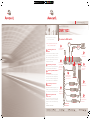
To connect a AutoView switch
Quick Installation Guide
AutoView
®
Switch
AutoView 2020 | AutoView 2030 Switches
Connecting power to the
AutoView switch
Power down all servers that will be part of your
AutoView switching system. Locate the power cord
that came with the AutoView switch. Plug one end
into the power socket on the rear of the AutoView
switch. Plug the other end into an appropriate AC
wall outlet.
Connecting the local port
Plug your VGA monitor, PS/2 or USB keyboard and
mouse cables into the appropriately labeled AutoView
switch ports.
Connecting a AVRIQ module to
the AutoView switch
Choose an available port on the rear of your AutoView
switch. Plug one end of a CAT 5 cable (4-pair, up to
10 meters) into a numbered port and plug the other
end into the RJ-45 connector of a AVRIQ module.
Connecting a server to the
AVRIQ module
Plug the AVRIQ module into the appropriate ports on
the back of the server. Repeat this procedure for all
servers that are to be connected to the AutoView switch.
Connecting network and
remote users
Plug a CAT 5 cable from your Ethernet network into the
LAN connector on the back of your AutoView switch.
Network users will gain access through this port.
1
2
4
5
3
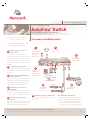
Plug in the
keyboard, monitor
and mouse for your
local connection.
Server
Local Connections
Server
Connect network
and remote users.
Connect AVRIQ
modules to the
AutoView switch.
Connect servers to the
AVRIQ modules.
Power down all
servers and attach
the appropriate
power cord to the
AutoView switch.
1
3
5
4
AutoView Switch
Check our web site at www.avocent.com/support to search the knowledge base or use the online request.
Avocent, the Avocent logo, The Power of Being There and AutoView are registered trademarks of Avocent Corporation or its affiliates. All other marks are the property of their respective owners. © 2005 Avocent Corporation. All rights reserved. 590-496-613A
6
Power up target
servers and then the
AutoView switch.
6
1357
2468
91113
10 12
14
15
16
1357
2468
91113
10 12
14
15
16
Ethernet
2

Zusatzinformationen
Zusätzliche Informationen bzgl. des AutoView Switches,
Software-Setup und der Sicherheitskonfiguration
können Sie der Installations- und Bedienungsanleitung
entnehmen, die mit dem Switch geliefert wurde. Die
aktuellen AutoView Switch-Software- und Firmware-
Updates können Sie unserer Webseite unter
http://register.avocent.com entnehmen.
Zielserver und den Switch
hochfahren
Fahren Sie zunächst die entsprechenden Server und
dann den AutoView Switch hoch.
Die folgenden Anweisungen helfen Ihnen beim
Anschluss Ihres AutoView Switches.
Nähere Informationen sind in Ihrer Installations-
und Bedienungsanleitung enthalten.
So schließen Sie einen AutoView Switch an:
Schnellinstallationsanleitung
AutoView
®
Switch
AutoView 2020 | AutoView 2030 Switches
Den AutoView Switch mit Strom
versorgen
Fahren Sie alle Server herunter, die an das AutoView
Switching-System angeschlossen werden sollen.
Verwenden Sie das Stromkabel, das mit dem
AutoView Switch geliefert wurde. Stecken Sie das
eine Kabelende in den Stromanschluss des AutoView
Switches auf der Geräterückseite. Stecken Sie das
andere Ende in eine geeignete Netzsteckdose.
Lokalen Port anschließen
Schließen Sie die VGA-Monitor-, die PS/2- oder
USB-Tastatur- und Mauskabel an die entsprechend
gekennzeichneten AutoView Switch-Ports an.
Ein AVRIQ-Modul an den
AutoView Switch anschließen
Wählen Sie einen verfügbaren Port auf der
Geräterückseite Ihres AutoView Switches aus.
Schließen Sie ein Ende eines CAT 5-Kabels (4 Paare,
bis zu 10 m) an einen nummerierten Port und das
andere Ende an einen RJ-45-Anschluss eines AVRIQ-
Moduls an.
Einen Server and as AVRIQ-
Modul anschließen
Schließen Sie das AVRIQ-Modul an die entsprechenden
Ports auf der Serverrückseite an. Wiederholen Sie dieses
Verfahren für alle Server, die an den AutoView Switch
angeschlossen werden sollen.
Netzwerk- und Remote-Benutzer
anschließen
Schließen Sie ein CAT 5-Kabel Ihres Ethernet-Netzwerks
an den LAN-Anschluss auf der Rückseite Ihres AutoView
Switches an. Netzwerk-Benutzer erhalten über diesen
Port Zugriff.
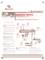
Schließen Sie
Tastatur, Monitor und
Maus für Ihre lokale
Verbindung an.
Server
Lokale Verbindungen
Server
Schließen Sie
Netzwerk- und
Remote-Benutzer an.
Schließen Sie
AVRIQ-Module
an den AutoView
Switch an.
Schließen Sie Server an
die AVRIQ-Module an.
Fahren Sie alle
Server herunter und
schließen Sie das
entsprechende
Netzkabel an den
AutoView Switch an.
AutoView Switch
Besuchen Sie unsere Website unter www.avocent.com/support, um auf die Knowledge Base zuzugreifen oder die Online-Serviceanforderung in Anspruch zu nehmen.
Avocent, das Avocent Logo, The Power of Being There und AutoView sind eingetragene Marken der Avocent Corporation oder ihrer Tochterunternehmen. Alle anderen Marken sind Eigentum der jeweiligen Unternehmen. © 2005 Avocent Corporation. Alle Rechte vorbehalten
Fahren Sie zunächst die
entsprechenden Server
und dann den AutoView
Switch hoch.
1357
2468
91113
10 12
14
15
16
1357
2468
91113
10 12
14
15
16
Ethernet

Informations complémentaires
Pour plus d’informations concernant la connexion du
commutateur AutoView, l’installation du logiciel et la
configuration des paramètres de sécurité, veuillez
consulter le guide d’installation et d’utilisation fourni
avec le commutateur. Pour obtenir les dernières mises
à jours du logiciel et du firmware du commutateur
AutoView, consultez le site http://register.avocent.com.
Mise sous tension des serveurs
cibles et du commutateur
Mettez sous tension chaque serveur cible, puis le
commutateur AutoView.
Suivez les instructions ci-dessous pour connecter
votre commutateur AutoView.
Pour tout renseignement supplémentaire, veuillez
consulter votre guide d’installation et
d’utilisation.
Connexion d’un commutateur AutoView
Guide d’installation rapide
Commutateur AutoView
®
Commutateurs AutoView 2020 | AutoView 2030
Connexion de l’alimentation au
commutateur AutoView
Mettez hors tension tous les serveurs qui seront
reliés au système de commutation AutoView.
Munissez-vous du cordon d’alimentation fourni avec
le commutateur AutoView puis branchez l’une de ses
extrémités dans la prise d’alimentation située à l’arrière
du commutateur et l’autre extrémité dans une prise
secteur appropriée.
Connexion à la voie locale
Branchez les câbles du moniteur VGA, du clavier et
de la souris PS/2 ou USB dans les voies
correspondantes du commutateur AutoView.
Connexion d’un module AVRIQ
au commutateur AutoView
Choisissez une voie disponible à l’arrière du
commutateur AutoView. Reliez un câble CAT 5 (câble
à quatre paires torsadées, jusqu’à 10 mètres de long)
à l’une des voies numérotées, d’une part, et au
connecteur RJ45 d’un module AVRIQ, d’autre part.
Connexion d’un serveur au
module AVRIQ
Branchez le module AVRIQ dans les voies
correspondantes situées à l’arrière du serveur. Répétez
cette procédure pour tous les serveurs que vous
souhaitez relier au commutateur AutoView.
Connexion au réseau et aux
utilisateurs distants
Branchez un câble CAT 5 relié à votre réseau Ethernet
dans le connecteur LAN situé à l’arrière du commutateur
AutoView. Les utilisateurs du réseau auront ainsi accès
au commutateur par cette voie.
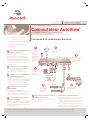
Branchez le clavier,
le moniteur et la
souris pour la
connexion locale.
Serveur
Connexions locales
Serveur
Connexion au réseau
et aux utilisateurs
distants.
Connectez les
modules AVRIQ
au commutateur
AutoView.
Connectez les serveurs
aux modules AVRIQ.
Mettez tous les
serveurs hors
tension et
connectez le cordon
d’alimentation
approprié au
commutateur
AutoView.
Commutateur AutoView
Consultez le site http://www.avocent.com/support et effectuez une recherche dans la base de connaissances ou utilisez le formulaire d’aide en ligne.
Avocent, le logo Avocent, The Power of Being There et AutoView sont des marques déposées d’Avocent Corporation ou de ses filiales. Toutes les autres marques sont la propriété exclusive de leurs détenteurs respectifs. © 2005 Avocent Corporation. Tous droits réservés.
Mettez sous tension
les serveurs cibles,
puis le commutateur
AutoView.
1357
2468
91113
10 12
14
15
16
1357
2468
91113
10 12
14
15
16
Ethernet

Información adicional
Para obtener información adicional sobre la conexión
del conmutador AutoView, la instalación del software
y la configuración de seguridad, consulte la guía de
uso e instalación que se incluye con el conmutador.
Visite http://register.avocent.com para obtener
información sobre las actualizaciones más recientes
del software y el firmware del conmutador AutoView.
Encendido de los servidores de
destino y del conmutador
Encienda todos los servidores de destino y, a
continuación, el conmutador AutoView.
Las instrucciones siguientes le ayudarán a
conectar el conmutador AutoView.
En caso de necesitar asistencia adicional,
consulte la guía de uso e instalación.
Conexión de un conmutador AutoView
Guía de instalación rápida
Conmutador AutoView
®
Conmutadores AutoView 2020 | AutoView 2030
Conexión de la alimentación al
conmutador AutoView
Apague todos los servidores que van a formar parte
del sistema de conmutación AutoView. Localice el
cable de alimentación que se incluye con el
conmutador AutoView. Enchufe un extremo en la
toma de alimentación situada en la parte posterior
del conmutador AutoView. Enchufe el otro extremo
en una toma de pared de CA apropiada.
Conexión del puerto local
Enchufe los cables del monitor VGA y del teclado y
del ratón PS/2 o USB en los puertos etiquetados
apropiados del conmutador AutoView.
Conexión de un módulo AVRIQ
al conmutador AutoView
Elija uno de los puertos disponibles situados en la
parte posterior del conmutador AutoView. Enchufe un
extremo de un cable CAT 5 (4 pares, de hasta 10
metros) en uno de los puertos numerados y el otro
extremo en el conector RJ-45 de un módulo AVRIQ.
Conexión de un servidor al
módulo AVRIQ
Enchufe el módulo AVRIQ en los puertos adecuados
de la parte posterior del servidor. Repita este
procedimiento para todos los dispositivos que vayan a
conectarse al conmutador AutoView.
Conexión de la red y de los
usuarios remotos
Enchufe un cable CAT 5 desde la red Ethernet al
conector LAN situado en la parte posterior del
conmutador AutoView. Los usuarios de red tendrán
acceso a través de este puerto.
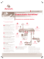
Conecte el
teclado, el monitor
y el ratón para la
conexión local.
Servidor
Conexiones locales
Servidor
Conecte la red y los
usuarios remotos.
Conecte los
módulos AVRIQ
al conmutador
AutoView.
Conecte los servidores
a los módulos AVRIQ.
Apague todos los
servidores y
conecte el cable
de alimentación
adecuado al
conmutador
AutoView.
Conmutador AutoView
Visite nuestro sitio Web en www.avocent.com/support para buscar en la base de información (knowledge base) o utilizar la solicitud de servicio en línea.
Avocent, el logotipo de Avocent, The Power of Being There y AutoView son marcas registradas de Avocent Corporation o sus afiliados. Todas las demás marcas pertenecen a sus respectivos propietarios. © 2005 Avocent Corporation. Todos los derechos reservados.
Conecte los servidores
de destino y, a
continuación, el
conmutador AutoView.
1357
2468
91113
10 12
14
15
16
1357
2468
91113
10 12
14
15
16
Ethernet

Ulteriori informazioni
Per ulteriori informazioni sui collegamenti dello switch
AutoView, sulle impostazioni del software e sulla
configurazione di protezione, fare riferimento alla
guida all’installazione e manuale dell’utente forniti
con lo switch. Per i più recenti aggiornamenti software
e firmware per lo switch AutoView, consultare il sito
Internet http://register.avocent.com.
Accensione dei server e dello
switch
Accendere ciascun server collegato, quindi lo switch
AutoView.
Istruzioni per il collegamento dello switch
AutoView.
Per ulteriori informazioni, fare riferimento alla
guida all’installazione e manuale dell’utente.
Collegamento di uno switch AutoView
Guida all'installazione rapida
Switch AutoView
®
Switch AutoView 2020 | AutoView 2030
Collegamento dello switch
AutoView all'alimentazione
Spegnere tutti i server da collegare al sistema di
commutazione AutoView. Individuare il cavo di
alimentazione in dotazione con lo switch AutoView
e collegarlo alla presa sul pannello posteriore dello
switch. Collegare l’altra estremità a una presa di
corrente alternata.
Collegamento alla porta locale
Collegare i cavi di monitor VGA, tastiera e mouse
PS/2 o USB alle porte corrispondenti dello switch
AutoView.
Collegamento di un modulo
AVRIQ allo switch AutoView
Scegliere una delle porte disponibili sul pannello
posteriore dello switch AutoView. Inserire un’estremità
di un cavo CAT 5 (a 4 doppini e di lunghezza massima
di 10 metri) in una porta numerata e l’altra estremità
nel connettore RJ-45 di un modulo AVRIQ.
Collegamento di un server al
modulo AVRIQ
Collegare il modulo AVRIQ alle porte corrispondenti sul
pannello posteriore del server. Ripetere l'operazione per
tutti i server da collegare allo switch AutoView.
Collegamento di utenti di rete
e remoti
Inserire un cavo CAT 5 collegato alla rete Ethernet nel
connettore LAN sul pannello posteriore dello switch
AutoView. Gli utenti di rete potranno accedere allo
switch AutoView tramite questa porta.
Collegare i cavi di
tastiera, monitor e
mouse della
postazione locale.
Server
Collegamenti locali
Server
Collegare gli utenti
di rete e remoti.
Collegare i moduli
AVRIQ allo switch
AutoView.
Collegare i server ai
moduli AVRIQ.
Spegnere tutti i
server e collegare
l'apposito cavo di
alimentazione allo
switch AutoView.
Switch AutoView
Per consultare la banca dati di supporto tecnico o richiedere assistenza on-line, visitare il sito Internet www.avocent.com/support.
Avocent, il logo Avocent, lo slogan The Power of Being There e AutoView sono marchi registrati di Avocent Corporation o delle società affiliate. Tutti gli altri marchi appartengono ai rispettivi proprietari. © 2005 Avocent Corporation. Tutti i diritti riservati.
Accendere i server
collegati, quindi lo
switch AutoView.
1357
2468
91113
10 12
14
15
16
1357
2468
91113
10 12
14
15
16
Ethernet

C M Y CM MY CY CMY K
The following instructions will help you
to connect your DSR switch.
Should you require further assistance, please
consult your installer/user guide.
Avocent, the Avocent logo, The Power of Being There and DSR are trademarks or registered trademarks of Avocent Corporation. All other marks are the property of their respective owners. ©2004 Avocent Corporation. All rights reserved. 590-390-118A
Connecting power to the
DSR switch
Power down all servers that will be part of your DSR
system. Locate the power cord that came with the
DSR switch. Plug one end into the power socket on
the rear of the DSR switch. Plug the other end into
an appropriate AC wall outlet.
Connecting the local port
Plug your VGA monitor, keyboard and PS/2 mouse
cables into appropriately labeled DSR ports.
Connecting a DSRIQ module to
the DSR switch
Choose an available port on the rear of your DSR
switch. Plug one end of a CAT 5 cable (4-pair, up to
10 meters) into a numbered port and plug the other
end into the RJ-45 connector of a DSRIQ module.
Connecting a server to the
DSRIQ module
Plug the DSRIQ module into the appropriate ports on
the back of the server. Repeat this procedure for all
servers that are to be connected to the DSR switch.
Connecting network and
remote users
Plug a CAT 5 cable from your Ethernet network into
the LAN connector on the back of your DSR switch.
Network users will access the DSR switch through
this port.
(Continued on reverse side)
1
2
4
5
A1
Plug in the keyboard,
monitor and mouse for
your local connection.
Serial server
SPC800 Power
Control Device
Local connection
PS/2 server
USB server
Sun server
Modem
Connect your
SPC device to
the target servers.
Plug in the
external modem.
Connect the switch
to the network.
Connect DSRIQ
modules to the
DSR switch.
The Power of Being There
To connect a DSR switch
3
2
7
Power down all
servers and attach
the appropriate
power cord to the
DSR switch.
1
3
5
6
Power up target
servers and then the
DSR switch.
8
Connect servers to
the DSRIQ modules.
4
Quick Installation Guide
DSR
TM
1021
Ethernet
Telephone
network
-
 1
1
-
 2
2
-
 3
3
-
 4
4
-
 5
5
-
 6
6


Avocent AutoView Series Quick Installation Manual
- Tipo
- Quick Installation Manual
- Questo manuale è adatto anche per
in altre lingue
- English: Avocent AutoView Series
- français: Avocent AutoView Series
- español: Avocent AutoView Series
- Deutsch: Avocent AutoView Series
Documenti correlati
Altri documenti
-
Black Box KV120E Guida utente
-
Emerson Avocent Universal Management Gateway Technical Manual
-
Belkin OMNIVIEW SMB CAT5 KVM SWITCH Manuale del proprietario
-
Vertiv Avocent MergePoint Unity Switch for Dell Quick Installation Guide
-
Intel 330T Manuale utente
-
ATEN KN8164V Guida Rapida
-
ATEN KL1108V Guida Rapida
-
ATEN KN2116VA Guida Rapida