
APPARECCHIATURA ELETTRONICA PER CANCELLI A BATTENTE 24Vdc
CONTROL BOARD FOR HINGED GATES 24Vdc
PLATINE ELECTRONIQUE POUR PORTAILS BATTANTS 24Vdc
EQUIPO ELECTRÓNICO PARA PORTONES DE TIPO BATIENTE 24Vdc
ELEKTRONISCHES GERÄT FÜR FLÜGELTORE 24Vdc
JA489
ISTRUZIONI PER L’USO – NORME DI INSTALLAZIONE
USE AND INSTALLATION INSTRUCTIONS
INSTRUCTIONS POUR L’EMPLOI – NORMES D’INSTALLATION
INSTRUCCIONES PARA EL USO – NORMAS DE INSTALACIÓN
BETRIEBSANLEITUNG - INSTALLATIONSVORSCHRIFTEN

AVVERTENZE PER L’INSTALLATORE
OBBLIGHI GENERALI PER LA SICUREZZA
1) ATTENZIONE! È importante per la sicurezza delle persone seguire atten-
tamente tutta l’istruzione. Una errata installazione o un errato uso del
prodotto può portare a gravi danni alle persone.
2) Leggere attentamente le istruzioni prima di iniziare l’installazione del
prodotto.
3) I materiali dell’imballaggio (plastica, polistirolo, ecc.) non devono esse-
re lasciati alla portata dei bambini in quanto potenziali fonti di pericolo.
4) Conservare le istruzioni per riferimenti futuri.
5) Questo prodotto è stato progettato e costruito esclusivamente per
l’utilizzo indicato in questa documentazione. Qualsiasi altro utilizzo non
espressamente indicato potrebbe pregiudicare l’integrità del prodotto
e/o rappresentare fonte di pericolo.
6) GENIUS declina qualsiasi responsabilità derivata dall’uso improprio o
diverso da quello per cui l’automatismo è destinato.
7) Non installare l’apparecchio in atmosfera esplosiva: la presenza di gas
o fumi infiammabili costituisce un grave pericolo per la sicurezza.
8) GENIUS non è responsabile dell’inosservanza della Buona Tecnica nella
costruzione delle chiusure da motorizzare, nonché delle deformazioni
che dovessero intervenire nell’utilizzo.
9) Prima di effettuare qualsiasi intervento sull’impianto, togliere l’alimenta-
zione elettrica.
10) Prevedere sulla rete di alimentazione dell’automazione un interruttore
onnipolare con distanza d’apertura dei contatti uguale o superiore a 3
mm. È consigliabile l’uso di un magnetotermico da 6A con interruzione
onnipolare.
11) Verificare che a monte dell’impianto vi sia un interruttore differenziale
con soglia da 0,03 A.
12) Verificare che l’impianto di terra sia realizzato a regola d’arte e collegar-
vi le parti metalliche della chiusura.
13) L’automazione dispone di una sicurezza intrinseca antischiacciamento
costituita da un controllo di coppia. E' comunque necessario verificarne
la soglia di intervento.
14) I dispositivi di sicurezza permettono di proteggere eventuali aree di
pericolo da Rischi meccanici di movimento, come ad Es. schiaccia-
mento, convogliamento, cesoiamento.
15) Per ogni impianto è consigliato l’utilizzo di almeno una segnalazione
luminosa nonché di un cartello di segnalazione fissato adeguatamente
sulla struttura dell’infisso, oltre ai dispositivi citati al punto “14”.
16) GENIUS declina ogni responsabilità ai fini della sicurezza e del buon
funzionamento dell’automazione, in caso vengano utilizzati compo-
nenti dell’impianto non di produzione GENIUS.
17) Per la manutenzione utilizzare esclusivamente parti originali GENIUS.
18) Non eseguire alcuna modifica sui componenti facenti parte del sistema
d’automazione.
19) L’installatore deve fornire tutte le informazioni relative al funzionamento
manuale del sistema in caso di emergenza e consegnare all’Utente
utilizzatore dell’impianto il libretto d’avvertenze allegato al prodotto.
20) Non permettere ai bambini o persone di sostare nelle vicinanze del
prodotto durante il funzionamento.
21) Tenere fuori dalla portata dei bambini radiocomandi o qualsiasi altro
datore di impulso, per evitare che l’automazione possa essere azionata
involontariamente.
22) Il transito tra le ante deve avvenire solo a cancello completamente
aperto.
23) L’Utente utilizzatore deve astenersi da qualsiasi tentativo di riparazione
o d’intervento diretto e rivolgersi solo a personale qualificato.
24) Tutto quello che non è previsto espressamente in queste istruzioni non è
permesso
IMPORTANT NOTICE FOR THE INSTALLER
GENERAL SAFETY REGULATIONS
1) ATTENTION! To ensure the safety of people, it is important that you read
all the following instructions. Incorrect installation or incorrect use of the
product could cause serious harm to people.
2) Carefully read the instructions before beginning to install the product.
3) Do not leave packing materials (plastic, polystyrene, etc.) within reach
of children as such materials are potential sources of danger.
4) Store these instructions for future reference.
5) This product was designed and built strictly for the use indicated in this
documentation. Any other use, not expressly indicated here, could
compromise the good condition/operation of the product and/or be a
source of danger.
6) GENIUS declines all liability caused by improper use or use other than
that for which the automated system was intended.
7) Do not install the equipment in an explosive atmosphere: the presence
of inflammable gas or fumes is a serious danger to safety.
8) GENIUS is not responsible for failure to observe Good Technique in the
construction of the closing elements to be motorised, or for any
deformation that may occur during use.
9) Before attempting any job on the system, cut out electrical power.
10) The mains power supply of the automated system must be fitted with an
all-pole switch with contact opening distance of 3mm or greater. Use
of a 6A thermal breaker with all-pole circuit break is recommended.
11) Make sure that a differential switch with threshold of 0.03 A is fitted
upstream of the system.
12) Make sure that the earthing system is perfectly constructed, and connect
metal parts of the means of the closure to it.
13) The automated system is supplied with an intrinsic anti-crushing safety
device consisting of a torque control. Nevertheless, its tripping threshold
must be checked as specified in the Standards indicated at point 10.
14) The safety devices protect any danger areas against mechanical
movement Risks, such as crushing, dragging, and shearing.
15) Use of at least one indicator-light is recommended for every system, as
well as a warning sign adequately secured to the frame structure, in
addition to the devices mentioned at point “14”.
16) GENIUS declines all liability as concerns safety and efficient operation of
the automated system, if system components not produced by GENIUS
are used.
17) For maintenance, strictly use original parts by GENIUS.
18) Do not in any way modify the components of the automated system.
19) The installer shall supply all information concerning manual operation of
the system in case of an emergency, and shall hand over to the user the
warnings handbook supplied with the product.
20) Do not allow children or adults to stay near the product while it is
operating.
21) Keep remote controls or other pulse generators away from children, to
prevent the automated system from being activated involuntarily.
22) Transit through the leaves is allowed only when the gate is fully open.
23) The user must not attempt any kind of repair or direct action whatever
and contact qualified personnel only.
24) Anything not expressly specified in these instructions is not permitted.
CONSIGNES POUR L'INSTALLATEUR
RÈGLES DE SÉCURITÉ
1) ATTENTION! Il est important, pour la sécurité des personnes, de suivre à
la lettre toutes les instructions. Une installation erronée ou un usage
erroné du produit peut entraîner de graves conséquences pour les
personnes.
2) Lire attentivement les instructions avant d'installer le produit.
3) Les matériaux d'emballage (matière plastique, polystyrène, etc.) ne
doivent pas être laissés à la portée des enfants car ils constituent des
sources potentielles de danger.
4) Conserver les instructions pour les références futures.
5) Ce produit a été conçu et construit exclusivement pour l'usage indiqué
dans cette documentation. Toute autre utilisation non expressément
indiquée pourrait compromettre l'intégrité du produit et/ou représenter
une source de danger.
6) GENIUS décline toute responsabilité qui dériverait d'usage impropre ou
différent de celui auquel l'automatisme est destiné.
7) Ne pas installer l'appareil dans une atmosphère explosive: la présence
de gaz ou de fumées inflammables constitue un grave danger pour la
sécurité.
8) GENIUS n'est pas responsable du non-respect de la Bonne Technique
dans la construction des fermetures à motoriser, ni des déformations qui
pourraient intervenir lors de l'utilisation.
9) Couper l'alimentation électrique avant toute intervention sur l'installation.
10) Prévoir, sur le secteur d'alimentation de l'automatisme, un interrupteur
omnipolaire avec une distance d'ouverture des contacts égale ou
supérieure à 3 mm. On recommande d'utiliser un magnétothermique
de 6A avec interruption omnipolaire.
11) Vérifier qu'il y ait, en amont de l'installation, un interrupteur différentiel
avec un seuil de 0,03 A.
12) Vérifier que la mise à terre est réalisée selon les règles de l'art et y
connecter les pièces métalliques de la fermeture.
13) L'automatisme dispose d'une sécurité intrinsèque anti-écrasement,
formée d'un contrôle du couple. Il est toutefois nécessaire d'en vérifier
le seuil d'intervention suivant les prescriptions des Normes indiquées au
point 10.
14) Les dispositifs de sécurité permettent de protéger des zones
éventuellement dangereuses contre les Risques mécaniques du
mouvement, comme l'écrasement, l'acheminement, le cisaillement.
15) On recommande que toute installation soit doté au moins d'une
signalisation lumineuse, d'un panneau de signalisation fixé, de manière
appropriée, sur la structure de la fermeture, ainsi que des dispositifs cités
au point “14”.

1
ITALIANO
APPARECCHIATURA ELETTRONICA PER CANCELLI A BATTENTE 24 Vdc
ISTRUZIONI PER L’USO - NORME DI INSTALLAZIONE
1. CARATTERISTICHE GENERALI
Questa centrale di comando per cancelli a battente 24 Vdc, grazie alla elevata potenza del microprocessore di cui è
dotata, offre un ampio numero di prestazioni e regolazioni, con rallentamento e controllo motore.
Un sofisticato controllo elettronico monitorizza costantemente il circuito di potenza ed interviene bloccando la centrale
in caso di anomalie che possano pregiudicare il corretto funzionamento della frizione elettronica.
I settaggi principali e i modi di funzionamento si effettuano mediante dip-switch mentre, le regolazioni dei tempi e della
potenza dei motori, si effettuano tramite autoapprendimento in fase di programmazione. 3 LEDS incorporati indicano
costantemente lo stato della centrale e del motoriduttore.
E’ disponibile un contenitore stagno predisposto per l’alloggiamento della centrale, delle batterie e del trasformatore
toroidale.
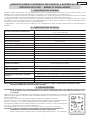
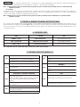
2. CARATTERISTICHE TECNICHE
IMPORTANTE: IL TRASFORMATORE MANTIENE IN CARICA LE BATTERIE, LE QUALI ALIMENTANO LA CENTRALE. NON E’
POSSIBILE ALIMENTARE LA CENTRALE SENZA BATTERIE.
3. PREDISPOSIZIONI
ATTENZIONE: E’ importante per la sicurezza delle persone seguire attentamente tutte le avvertanze e istruzioni presenti
in questo libretto. Una errata installazione o un errato uso del prodotto può essere fonte di pericolo per cose
e/o persone.
Verificare che a monte dell’impianto vi sia un adeguato interruttore differenziale come prerscritto
dalla normativa vigente e prevedere sulla rete di alimentazione un magnetotermico con inter-
ruzione onnipolare.
Per la messa in opera dei cavi elettrici utilizzare adeguati tubi rigidi e/o flessibili.
Separare sempre i cavi di collegamento degli accessori a bassa tensione da quelli di alimen-
tazione a 115/230 V~. Per evitare qualsiasi interferenza utilizzare guaine separate.
La lunghezza massima dei cavi di alimentazione tra centrale e motori non deve essere superio-
re ai 10 m., utilizzando cavi con sezione da 2.5mm².
Per il fissaggio dei vari componenti nel contenitore stagno, procedere come segue:
Nota bene: il supporto è dimensionato per alloggiare un trasformatore e due batterie con
caratteristiche e dimensioni specificate nella tabella del paragrafo 2.
1) Fissare il supporto per il trasformatore toroidale nella posizione A con n.3 viti Ø4.2x13
A
B
C
erotamrofsartenoizatnemilaenoisneT
zH05)%01-%6+(~V032
zH06)%01-%6+(~V511
arutaihccerappaenoizatnemilaenoisneT zH06/05)%01-%6+(~V22
atibrossaaznetoP W3
erotom.xamociraC W07x2
irossecca.xamocoraC Am005cdV42
erotaiggepmal.xamociraC .xamW51cdV42
etneibmaarutarepmeT C°55+C°02-
enoizetorpidilibisuF 2
otnemanoiznufidehcigoL ossap-ossap/acitamotuA
arusuihc/arutrepaopmeT enoizallatsniniotnemidnerppaotuA
asuapidopmeT enoizallatsniniotnemidnerppaotuA
atnipsidazroF hciws-pidnocilibanoizelesillevileuD
atnaidratiR hciws-pidnocilibanoizelesillevileuD
itnematnellaR otnemidnerppaotuaniarusuihcearutrepanI
areittesromniissergnI
arutrepA/elatotarutrepA/eirettabenoizatnemilA/~V22enoizatnemilA
elullecotoF/potS/elanodep
odiparerottennoC PRitnevecir-acifidocedadehcsreP
areittesromnieticsU
/cdV42irotoM/cdV42irosseccaenoizatnemilA
cdV42aipsadapmaL/cdV42erotaiggepmaL/arutarresorttelE
adehcsinoisnemiD mm031x071
eladioroterotamrofsartehcitsirettaraC
)lanoitpo(
mm04x501Øinoisnemid/AV051/~V22oiradnoceS~V032oiramirP
mm04x501Øinoisnemid/AV051/~V22oiradnoceS~V511oiramirP
)lanoitpo(eirettabehcitsirettaraC mm801x07x09inoisnemiD/hA5.4V21
onretsereperotinetnocehcitsirettaraC 55PI-mm521x522x503

2
ITALIANO
autofilettanti (fornite), ponendo i distanziali tra supporto e guide del contenitore stagno.
2) Fissare il trasformatore al supporto con le n.2 fascette (fornite).
3) Fissare il supporto per le batterie nella posizione B con n.4 viti Ø3.5x9.5 autofilettanti (fornite) nei fori di incrocio
delle guide del contenitore stagno.
4) Posizionare le batterie sul supporto.
5) Fissare la centrale nella posizione C con n.4 viti Ø4.2x13 autofilettanti (fornite), ponendo i distanziali tra scheda
e guide del contenitore stagno.
4. COLLEGAMENTI E FUNZIONAMENTO
4.1 MORSETTIERA M1
4.1.1 Alimentazione 22V
Morsetti “1-2”. Ingresso al quale va collegato il secondario con alimentazione 22 V~ 50/60 Hz del trasformatore. La
presenza di alimentazione per mezzo del trasformatore è segnalata dall’accensione del led POWER.
4.1.2 Batterie
Morsetti “3-4”. La centrale funziona solo con le batterie collegate. Le batterie devono rispettare le caratteristiche minime
riportate nella tabella del paragrafo 2.
Durante il funzionamento normale il trasformatore alimenta la scheda tramite le batterie. Quando viene a mancare
l’alimentazione al trasformatore le batterie continuano ad alimentare la scheda.
Nota bene: l’alimentazione con le sole batterie è da considerarsi una situazione di emergenza, il numero di manovre
minimo è circa di 10/15 manovre. Comunque il numero delle manovre possibili è legato alla qualità delle
batterie stesse, struttura del cancello da movimentare, da quanto tempo è passato dalla sospensione
dell’alimentazione di rete, ect., ect..
Nota bene: rispettare le polarità di alimentazione delle batterie.
4.1.3 Accessori
Morsetti “5-6”. Uscita per alimentazione accessori esterni (24 Vdc).
Nota bene: il carico max degli accessori è di 500 mA.
4.1.4 Massa a terra
Morsetto apposito o cavo di massa. Collegare la massa a terra della rete.
Nota bene: collegamento assolutamente necessario per il corretto funzionamento della centrale.
4.2 MORSETTIERA M2
4.2.1 Motoriduttore 1
Morsetti “7-8”. Collegare il motore dell’anta 1 per cancelli a doppio battente con alimentazione 24Vdc 70W max. Da
utilizzare per il collegamento del motoriduttore per cancelli ad una anta.
4.2.2 Motoriduttore 2
Morsetti “9-10”. Collegare il motore dell’anta 2 per cancelli a doppio battente con alimentazione 24Vdc 70W max. Non
collegare per cancelli ad una anta.
4.2.3 Elettroserratura
Morsetti “11-12”. Collegare un’elettroserratura con alimentazione 24Vdc 24W max. A seconda della struttura del cancello
e del tipo di elettroserratura montata, è possibile con il dip-switch 5 inserire il colpo di inversione d’anta che permette
all’elettroserratura di sganciarsi.
Nota bene: montare l’elettroserratura sull’anta dove è montato il motoriduttore 1.
4.2.4 Lampeggiante
Morsetti “13-12”. Utilizzare un lampeggiatore a luce fissa con tensione di funzionamento 24Vdc 15W max. E’ utile collegar-
lo prima della fase di programmazione perchè ne indica le fasi. In apertura esegue un prelampeggio fisso di 0.5 secondi,
in chiusura di 1.5 secondi. Se è inserita la logica automatica, quando raggiunge la battuta di apertura. il lampeggiante
resta acceso fisso per 5 sec., per segnalare all’utente che richiuderà automaticamente. A cancello aperto il lampeg-
giante è spento, lampeggia solo nel momento in cui vengono impegnate le sicurezze; se queste restano impegnate per
molto tempo, il lampeggio durerà solo per 10 sec.
4.2.5 Luce spia
Morsetti “14-12”. Utilizzare un lampada spia con tensione di funzionamento 24Vdc 3W max. Con cancello chiuso la spia
è spenta, durante le fasi di apertura, cancello aperto e chiusura è accesa.
4.3 MORSETTIERA M3
4.3.1 Open B - Pedonale
Morsetti “15-19”. A questo circuito va collegato qualsiasi dispositivo (es. pulsante, radiocomando, ect.) che, chiudendo
un contatto, genera un impulso d’apertura parziale del cancello. Se il cancello è a due ante un impulso aprirà comple-
tamente l’anta collegata al motoriduttore 1; se il cancello è ad una anta aprirà parzialmente l’anta (50% del tempo
lavoro)
Nota bene: un impulso di START durante la fase pedonale ha sempre priorità sulla stessa
Nota bene: Per installare più datori di impulsi collegare i contatti in parallelo.
4.3.2 Open A - Start
Morsetti “16-19”. A questo circuito va collegato qualsiasi dispositivo (es. pulsante, radiocomando, ect.) che, chiudendo

3
ITALIANO
un contatto, genera un impulso d’apertura e/o chiusura totale del cancello. Il suo funzionamento è definito dal dip-
switch 3, vedi paragrafo relativo.
Nota bene: un impulso di START durante la fase pedonale ha sempre priorità sulla stessa
Nota bene: Per installare più datori di impulsi collegare i contatti in parallelo.
4.3.3 Fotocellule
Morsetti “17-19”. A questo circuito va collegato qualsiasi dispositivo di sicurezza (fotocellule, costa di sicurezza, ect.) che,
aprendo un contatto, ha un effetto di sicurezza sul moto di chiusura. Lo stato di questo ingresso è segnalato mediante il
led FTO. Ha effetto anche sul moto di apertura in funzione di come è settato il dip-switch 4, vedi paragrafo relativo.
Nota bene: Se non vengono collegati dispositivi di sicurezza ponticellare l’ingresso. Per installare più dispositivi di
sicurezza collegare i contatti NC in serie.
4.3.4 Stop
Morsetti “18-19”. A questo circuito va collegato qualsiasi dispositivo (es. pulsante, pressostato, ect.) che, aprendo un
contatto, arresta il moto del cancello. Lo stato di questo ingresso è segnalato mediante il led STOP. Solo un successivo
impulso di apertura o chiusura riprende il ciclo impostato.
Nota bene: Se non vengono collegati dispositivi di STOP ponticellare l’ingresso. Per installare più dispositivi di STOP
collegare i contatti NC in serie.
5. INSERIMENTO SCHEDA RICEVITORE PER TELECOMANDO
La centrale è predisposta per alloggiare un modulo radioricevitore 5 pin. Per procedere all’installazione togliere l’alimen-
tazione elettrica e inserire il modulo nell’apposito connettore M5 all’interno della centrale. Seguire poi le istruzioni del
radio-ricevitore per la memorizzazione del telecomando. Una volta memorizzato il telecomando agisce come un qualsi-
asi dispositivo di comando sullo START.
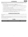
6. LEDS DI CONTROLLO
Nota bene: in neretto la condizione dei leds con cancello chiuso e centrale alimentata.
7. SETTAGGI CON DIP-SWITCH S1
DELOSECCAOTNEPS
-REWOP enoizatnemila erotamrofsartnoc )etsiverpes(eirettabnoc
-OTF elullecotof erebilelullecotof etangepmielullecotof
pots-POTSovittaniodnamoc ovittaodnamoc
1WS
ACINORTTELEENOIZIRF
5WS
ATNAENOISREVNI'DOPLOC
àtilibisnesaminim,azrofamissaMNO
5.1reparusuihcnioplocnueugese,osulcnINO
idnoces
àtilibisnesamissam,azrofaminiMFFO osulcsEFFO
2WS
OTNEMANOIZNUFIDACIGOL
6WS
ATNAIDRATIR
acitamotuaNO
21arusuihcni,idnoces2arutrepanINO
idnoces
ossaP-ossaPFFO
4arusuihcni,idnoces2arutrepanIFFO
idnoces
3WS
ARUTREPAODNAMOCOTNEMANOIZNUF
7WS
OLLECNAC
,pots,erpa:otatsolosnuoslupmiingodANO
.....erpa,pots,eduihc
;arutrepaetnarudTRATSidislupmietnesnon
opmetetepirarusuihcni;asuapnièesasuap
etrevnideaccolb
itagellocirotomeud,etnaeudANO
,erpa:otnemivomolosnuoslupmiingodaFFO
.....erpa,eduihc
otagellocerotomnu,atnaanudaFFO
4WS
ELULLECOTOFOTNEMANOIZNUF
ni;rpaongepmisidladeaccolbarutrepanINO
etrevnideaccolbarusuihc
etrevnideaccolbarusuihcnioloSFFO

4
ITALIANO
8. PROGRAMMAZIONE
La programmazione dei tempi di lavoro, dei rallentamenti e della frizione elettronica avvengono in autoapprendimento,
il movimento delle ante in questa fase avviene in maniera rallentata. Procedere quindi nel seguente modo:
1) Sbloccare le ante e portarle a circa metà apertura, poi ribloccarla.
2) Alimentare la centrale (l’alimentazione è segnalata dall’accensione del led POWER).
3) Spostare l’interruttore S2 su PROG, il lampeggiante si accenderà a luce fissa per segnalare che si è in fase di
programmazione.
4) Premere il pulsante collegato sui morsetti di START oppure il telecomando, se già memorizzato. La prima
manovra che l’automazione compie deve essere di CHIUSURA. Per prima si chiuderà l’anta collegata a M2,
poi quella collegata a M1.
5) Se le ante si movimentano in apertura, toccare con un cacciavite i due pins di RESET, la centrale bloccherà
immediatamente il moto dell’automazione.
6) Togliere l’alimentazione alla centrale, invertire la polarità dei due cavi di alimentazione dei motori che si sono
movimentati in apertura e ripetere l’operazione dal punto 1.
7) Dopo il comando di START, le ante si movimentano in chiusura, fino a raggiungere la battuta di chiusura.
8) Dopo circa due secondi l’anta collegata a M1 riparte automaticamente in apertura, dopo altri due secondi
riparte anche l’anta collegata a M2 fino a raggiungere le battute di apertura.
9) La centrale inizia il conteggio del tempo di pausa; trascorso il tempo desiderato, premere ancora il comando
di START, l’anta collegata a M2 riparte in chiusura, dopo il tempo di sfasamento impostato riparte anche
l’anta collegata a M1 fino a raggiungere le battute di chisusura.
10) A questo punto la fase di programmazione è terminata; riporre l’interruttore S2 su OFF, il lampeggiante si
spegnerà.
9. FUNZIONAMENTO DELLA FRIZIONE ELETTRONICA
Dispositivo importantissimo ai fini della sicurezza, la sua taratura resta costante nel tempo senza essere soggetta ad usure
o cambiamenti di taratura.
Essa è attiva sia in chisura che in apertura, quando interviene inverte la marcia senza disabilitare la chiusura automatica
nel caso essa sia inserita.
Se interviene per 2 volte consecutive, si posiziona in STOP disabilitando qualsiasi comando automatico, questo perchè
intervenendo per 2 volte significa che l’ostacolo permane e potrebbe essere pericoloso effettuare qualsiasi manovra
ulteriore costringendo così l’utente a dare un comando di apertura o chiusura.
Se interviene per più di 90 Sec. consecutivi la centrale esegue una procedura di EMERGENZA dove andrà ad effettuare
obbligatoriamente una apertura completa tutta in rallentamento sino al fermo battuta di apertura per poi richiudersi
automaticamente in modo da risincronizzarsi le battute autonomamente.
10. FUSIBILI DI PROTEZIONE
ELIBISUFENOIZETORPELIBISUFENOIZETORP
1F 02X5V052A51.3F=irosseccaaticsu/acigol 2F 02X5V052A01T=erotom

5
ITALIANO
123
45
6
172345
6
PROG
OFF
S1
S2
ON
OFF
F1
F 3.15A - 250V
F2
T 10A - 250V
M1
M3M2
M5
RESET
STOPFTO
POWER
789
10
11
12
13
14
15 16
17
18
19
M2
1
2
3
4
5
1
2
TX RX
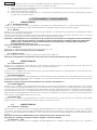
Altre sicurezze
Other safeties
Autres sécurités
Andere Sicherheiten
Otros disp. seg.
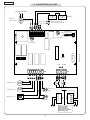
M1
115/230Vac 50Hz
alimentazione
accessori
Trasformatore
toroidale
Motoriduttore 1
Elettroserratura
Lampada
spia
Lampeggiatore
Motoriduttore 2
Batterie
Connettore per
ricevente 5 pin
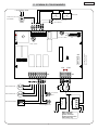
11. SCHEMA DI COLLEGAMENTO

6
ENGLISH
CONTROL BOARD FOR 24 Vdc SWING-LEAF GATES
OPERATING INSTRUCTIONS – INSTALLATION INSTRUCTIONS
1. GENERAL CHARACTERISTICS
Thank to its high powered microprocessor, this control unit for 24 Vdc sing-leaf gates offers a wide range of functions and
adjustments, including deceleration and motor control.
A sophisticated electronic control monitors the power circuit at all times and disables the control unit in the event of
malfunctions that could impair efficiency of the electronic clutch.
Main settings and function modes are executed by dip switches, whereas timing, and also power of motors are adjusted
through self-learning at programmation. 3 built-in LEDs constantly indicate status of both control unit and gearmotor.
The control unit is designed for installation in a watertight outdoor use container, which is also designed to house 2
optional batteries and a toroidal transformer, with the characteristics shown in the table below.
2. TECHNICAL SPECIFICATIONS
IMPORTANT: THE TRASFORMER KEEPS THE BATTERY CHARGED, WICH THEY SUPPLING POWER TO THE ELETTRONIC BOARD. IT
IS NOT POSSIBLE SUPPLY DIRECTLY THE ELETTRONIC BOARD WITHOUT USING THE TWO BATTERIES.
3. INSTRUCTIONS
WARNING: To ensure people’s safety, all warnings and instructions in this booklet must be carefully observed. Wrong use
or installation of the product, it can be dangerous for persons and things.
Make sure there is an adequate differential switch upstream of the system as specified by current laws, and install a
thermal breaker with all-pole switch on the electrical mains.
To lay electrical cables, use adequate rigid and/or flexible tubes.
Always separate connection cables of low voltage accessories from those operating at 115/
230 V~. To prevent any interference whatever, use separate sheaths.
The maximum length of power cables between control unit and motors must not exceed 10
m, using cables of 2.5mm² diameter.
Procedure for securing components in the watertight container:
N.B.: The support has been studied for store one trasformer, and two batteries with
characteristics and dimensions mentioned in the table present on the pharagraph
number 2.
1) Secure the support of the toroidal transformer in position A by fitting three Ø4.2x13
self-tapping screws (supplied), locating the spacers between support and guides
of the watertight container.
2) Secure the transformer on the support with 2 clamps (supplied).
A
B
C
remrofsnartfoegatlovylppuS
zH05)%01-%6+(~V032
zH06)%01-%6+(~V511
tinulortnocfoegatlovylppuS zH05)%01-%6+(~V22
noitpmusnocrewoP W3
daol.xamrotoM W07x2
daol.xamseirosseccA Am005cdV42
daol.xamthgilhsalF .xamW51cdV42
etneibmaarutarepmeT C°55+C°02-
esuF 2
scigolnoitcnuF deppetS/citamotuA
emitgnisolc/gninepO noitallatsnitagninrael-fleshguorhT
emitesuaP noitallatsnitagninrael-fleshguorhT
ecroftsurhT hctiws-piDybdetcelesslevelowT
secnereffidemiT hctiws-piDybdetcelesslevelowT
noitareleceD gninrael-flesgnirudgnisolcdnagninepotA
stupnidraoblanimreT
/gninepolatoT/ylppusrewopyrettaB/ylppusrewop~V22
potS/sllecotohP/snairtsedeprofgninepO
rotcennocoidaR sdracnoitpeceroidaR
stuptuodraoblanimreT
cdV42/kcolcirtcelE/srotoMcdV42/ylppusrewopseirosseccacdV42
thgil-gninraWcdV42/thgilhsalF
snoisnemiddraC mm031x071
remrofsnartladiorotfoscitsiretcarahC
)lanoitpo(
.mm04x501Ø.snemid/AV021/~V22.ces-~V032.mirp
.mm04x501Ø.snemid/AV021/~V22.ces-~V511.mirp
seirettablanoitpofoscitsiretcarahC
)lanoitpo(
snemiD/hA5.4V21
.
mm801x07x09
reniatnocroodtuofoscitsiretcarahC 55PI-mm521x522x503

7
ENGLISH
3) If using floating batteries, secure the relevant support in position B by fitting four Ø3.5x9.5 self-tapping screws
(supplied) in the crossover holes of the guides of the watertight container.
4) Position the batteries on the support.
5) Secure the control unit in position C by fitting four Ø4.2x13 self-tapping screws (supplied), locating the spacers
between card and guides of the watertight container.
4. CONNECTIONS AND OPERATION
4.1 TERMINAL BOARD M1
4.1.1 22V power supply
Terminals “1-2”. This is the input to which the secondary winding of the transformer, powered at 22 V 50/60 Hz, should be
connected. When power is supplied by the transformer, this is signalled by the POWER LED lighting up.
4.1.2 Batteries
Terminals “3-4”. The elettronic board is operative only with batteries connected. The batteries must respect the minimum
technical dates mentioned in the table present on the paragraph number 2.
N.B.: During the normal finction the trasformer supplies power to the elettronic board through the batteries. In case of
black out even if no power is supplied to the transform, the two batterie keep up the elettronic board
supplied.
N.B.: In case of emergency, through the batteries it can be done from 10 to15 operations, the exactly number of them
it depends on the quality of the batteries as well as from type of gate to be moved.
4.1.3 Accessories
Terminals “5-6”. Output for powering external accessories (24 Vdc).
N.B.: Maximum load of accessories is 500 mA.
4.1.4 Earth
Dedicated terminals or mass cable. Connect earth to a source.
N.B.: this connection is absolutely necessary for a proper functioning of the control bord.
4.2 TERMINAL BOARD M2
4.2.1 Gearmotor 1
Terminals “7-8”. Connect the motor for leaf 1 of twin-leaf gates to power supply of 24 Vdc 70W max. Use for gearmotor
connection for single-leaf gates.
4.2.2 Gearmotor 2
Terminals “9-10”. Connect the motor for leaf 2 of twin-leaf gates to power supply of 24 Vdc 70W max. Do not connect for
single-leaf gates.
4.2.3 Electric lock
Terminals “11-12”. Connect an electric lock operating on 24Vdc 24W max power supply. Depending on gate structure
and type of electric lock fitted, dip-switch 5 can be used to connect the leaf reverse pulse enabling the electric lock to
release.
N.B.: install the electric lock on the leaf on which gearmotor 1 is fitted.
4.2.4 Flashlight
Terminals “13-12”. Use a flashlight with fixed lamp-holder operating voltage of 24Vdc 15W max. We advise you to connect
it before programming, as it indicates programming stages. On opening, it pre-flashes steadily for 0.5 seconds, and for 1.5
seconds at closing. If the automatic logic is on, when the gate reaches the opening gate stop, the flashlight stays on for
5 sec to inform the user it will re-close automatically. When the gate is open, the flashlight is off, and only flashes when the
safety devices are in use. If the devices are in use for a long time, flashing only lasts 10 sec.
4.2.5 Warning-light
Terminals “14-12”. Use a warning-light operating on 24Vdc 3W max. When the gate is closed, the warning-light is off, and
goes on at opening, gate open and closing stages.
4.3 TERMINAL BOARD M3
4.3.1 Open B - For pedestrian use
Terminals “15-19”. Any device (e.g. push-button, remote control, etc.) can be connected to this circuit. By closing a
contact, the circuit generates a pulse for partial opening of the gate. If the gate has two leaves, a pulse fully opens the
leaf connected to gearmotor 1. If the gate has one leaf only, the pulse partly opens the leaf (50% of work time).
N.B.: a START pulse during the pedestrian stage always has priority over that stage
N.B.: to install several pulse generators, connect the contacts in parallel.
4.3.2 Open A - Start
Terminals “16-19”. Any device (e.g. push-button, remote control, etc.) can be connected to this circuit. By closing a
contact, the circuit generates a pulse for total opening and/or closing of the gate. Its operating mode is set by dip-switch
3 – see the relevant paragraph.
N.B.: a START pulse during the pedestrian stage always has priority over that stage
N.B.: to install several pulse generators, connect the contacts in parallel.
4.3.3 Photocells
Terminals “17-19”. Any safety device (e.g. photocell, sensitive strip, etc.) can be connected to this circuit. By opening a

8
ENGLISH
contact, the circuit protects closing motion. The status of this input is signalled by the FTO LED. It also has an effect on
opening motion, depending on how dip-switch 4 was set – see relevant paragraph.
N.B.: If safety devices are not connected, fit a jumper at input. To install several safety devices, connect the NC
contacts in series.
4.3.4 Stop
Terminals “18-19”. Any device (e.g. push-button, remote control, etc.) can be connected to this circuit. By opening a
contact, the circuit stops gate movement. The status of this input is signalled by the STOP LED. The set cycle will restart
only if a successive opening or closing pulse is received.
N.B.: If STOP devices are not connected, fit a jumper at input. To install several STOP devices, connect the NC
contacts in series.
5. FITTING A REMOTE CONTROL RECEIVER CARD
The control unit is designed to house a single- or twin-channel radio-receiver module. Installation procedure: turn off
power and fit the module in container M5 inside the control unit. Then observe the radio-receiver instructions to store data
on the remote-control. After the necessary data has been stored, the remote-control activates START like any other
command device.
6. CONTROL LEDS
N.B.: LED status shown in bold with gate closed and control unit powered.
7. SETTINGS WITH DIP-SWITCH S1
SDELDETHGILFFO
rewop-REWOPremrofsnarthtiW )desufi(seirettabnO
sllecotohp-OTFderevoctonsllecotohP derevocsllecotohP
pots-POTSevitcanidnammoC evitcadnammoC
1WS
HCTULCCINORTCELE
5WS
ESLUPESREVERFAEL
ytivitisnesmuminim,ecrofmumixaMNO
tasdnoces5.1rofeslupasetareneg:NO
gnisolc
FFO
ytivitisnesmumixam,ecrofmuminiM
FFO
2WS
CIGOLNOITCNUF
6WS
DNA1ROTOMNEEWTEBECNEREFFIDEMIT
2ROTOM
citamotuANO
tasdnoces21,gninepotasdnoces2NO
.gnisolc
deppetSFFO
tasdnoces4,gninepotasdnoces2FFO
.gnisolc
3WS
DNAMMOCGNINEPOFONOITAREPO
7WS
ETAG
,pots,nepo;esluphcaetaylnoetatsenONO
.ctenepo,pots,esolc
staeper,gninepognirudseslupTRATSonstceted
tasesreverdnaspots;esuapnifiemitesuap
gnisolc
detcennocsrotomraegowt:fael-niwTNO
,nepo:esluphcaetaylnotnemevomenoFFO
.cte,nepo,esolc
detcennocrotomraegeno:fael-elgniSFFO
4WS
SLLECOTOHPFONOITAREPO
taspots,esaelernostratser,gninepotaspotSNO
.sesreverdnagnisolc
.ylnognisolctasesreverdnaspotSFFO

9
ENGLISH
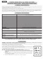
FUSE PROTECTING FUSE PROTECTING
F1 = F 3.15A 250V 5X20 Logic / Accessories output F2 = T 10A 250V 5X20 Motor
8. PROGRAMMING
Setting of control board must be done when panel is connected to a 115/230V~ source, through trasformers, as setting just
through batteries is not possible. Acting in this way all functions and timing of the control board will be properly programmed.
Programming of work times, deceleration and electronic clutch is executed during self-learning. At this stage, leaf movement
is at slow speed. Procedure:
1) Release the leaves, take them to about midway through opening travel, and then lock them
2) Power up the control unit (power ON is signalled by the POWER LED).
3) Turn switch S2 to PROG: the flashlight goes on at steady light to signal programming.
4) Press the push-button connected to the START terminals or the remote-control, if data has been stored. The
first operation the automation performs must be CLOSING. First, the leaf connected to M2 closes, and then the
one connected to M1.
5) If the leaves move to open, touch the two RESET pins with a screwdriver – the control unit will immediately stop
the movement generated by the automation.
6) Cut power to the control unit, reverse polarity of the two cables powering the motors which had supplied
opening drive, and repeat the operation at point 1.
7) After the START command is given, the leaves move to close, until they reach the closing gate stop.
8) After about two seconds, the leaf connected to M1 restarts opening automatically, and after another two
seconds, the leaf connected to M2 also restarts until it reaches the opening gate stops.
9) The control unit begins counting pause time. After the required time has elapsed, press the START command
again, and the leaf connected to M2 restarts closing. After the set time difference has elapsed, the leaf
connected to M1 restarts too until it reaches the closing gate stops.
10) Programming is now finished. Turn switch S2 back to OFF – the flashlight goes off.
9. OPERATION OF ELECTRONIC CLUTCH
This is a very important device for safety. Its setting does not alter through time, as the device is not subject to wear or
setting changes.
It is active both at closing and opening. When it operates it reverses motion direction without inhibiting automatic closing
if enabled.
If it operates twice in succession, it moves to STOP position, disabling any automatic command. This is why: if the clutch
operates twice, this means the obstacle is still present and any further manoeuvres could be dangerous, thus obliging the
user to give an opening or closing command.
If the clutch operates for more than 90 consecutive seconds, the control unit executes an EMERGENCY procedure as
follows: full opening at slow speed up to the opening gate stop, followed by automatic closing to enable the gate stops
to re-synchronise independently.
10. FUSES

10
ENGLISH
123
45
6
172345
6
PROG
OFF
S1
S2
ON
OFF
F1
F 3.15A - 250V
F2
T 10A - 250V
M1
M3M2
M5
RESET
STOPFTO
POWER
789
10
11
12
13
14
15 16
17
18
19
M2
1
2
3
4
5
1
2
TX RX
Altre sicurezze
Other safeties
Autres sécurités
Andere Sicherheiten
Otros disp. seg.
M1
115/230Vac 50Hz
Batteries
Receive plug
Toroidal
transformer
Power supplies to
external accessories
Gearmotor 1
Flashlight
Electric lock
Gearmotor 2
Warning-
light
11. CONNECTION LAY-OUT

16) GENIUS décline toute responsabilité quant à la sécurité et au bon
fonctionnement de l'automatisme si les composants utilisés dans
l'installation n'appartiennent pas à la production GENIUS.
17) Utiliser exclusivement, pour l'entretien, des pièces GENIUS originales.
18) Ne jamais modifier les composants faisant partie du système
d'automatisme.
19) L'installateur doit fournir toutes les informations relatives au
fonctionnement manuel du système en cas d'urgence et remettre à
l'Usager qui utilise l'installation les "Instructions pour l'Usager" fournies
avec le produit.
20) Interdire aux enfants ou aux tiers de stationner près du produit durant le
fonctionnement.
21) Eloigner de la portée des enfants les radiocommandes ou tout autre
générateur d'impulsions, pour éviter tout actionnement involontaire de
l'automatisme.
22) Le transit entre les vantaux ne doit avoir lieu que lorsque le portail est
complètement ouvert.
23) L'Usager qui utilise l'installation doit éviter toute tentative de réparation
ou d'intervention directe et s'adresser uniquement à un personnel
qualifié.
24) Tout ce qui n'est pas prévu expressément dans ces instructions est
interdit.
ADVERTENCIAS PARA EL INSTALADOR
REGLAS GENERALES PARA LA SEGURIDAD
1) ¡ATENCION! Es sumamente importante para la seguridad de las personas
seguir atentamente las presentes instrucciones. Una instalación incorrecta
o un uso impropio del producto puede causar graves daños a las
personas.
2) Lean detenidamente las instrucciones antes de instalar el producto.
3) Los materiales del embalaje (plástico, poliestireno, etc.) no deben
dejarse al alcance de los niños, ya que constituyen fuentes potenciales
de peligro.
4) Guarden las instrucciones para futuras consultas.
5) Este producto ha sido proyectado y fabricado exclusivamente para la
utilización indicada en el presente manual. Cualquier uso diverso del
previsto podría perjudicar el funcionamiento del producto y/o
representar fuente de peligro.
6) GENIUS declina cualquier responsabilidad derivada de un uso impropio
o diverso del previsto.
7) No instalen el aparato en atmósfera explosiva: la presencia de gas o
humos inflamables constituye un grave peligro para la seguridad.
8) GENIUS no es responsable del incumplimiento de las buenas técnicas
de fabricación de los cierres que se han de motorizar, así como de las
deformaciones que pudieran intervenir en la utilización.
9) Quiten la alimentación eléctrica antes de efectuar cualquier
intervención en la instalación.
10) Coloquen en la red de alimentación de la automación un interruptor
omnipolar con distancia de apertura de los contactos igual o superior
a 3 mm. Se aconseja usar un magnetotérmico de 6A con interrupción
omnipolar.
11) Comprueben que la instalación disponga línea arriba de un interruptor
diferencial con umbral de 0,03 A.
12) Verifiquen que la instalación de tierra esté correctamente realizada y
conecten las partes metálicas del cierre.
13) La automación dispone de un dispositivo de seguridad antiaplastamiento
constituido por un control de par. No obstante, es necesario comprobar
el umbral de intervención según lo previsto en las Normas indicadas en
el punto 10.
14) Los dispositivos de seguridad permiten proteger posibles áreas de
peligro de Riesgos mecánicos de movimiento, como por ej.
aplastamiento, arrastre, corte.
15) Para cada equipo se aconseja usar por lo menos una señalización
luminosa así como un cartel de señalización adecuadamente fijado a
la estructura del bastidor, además de los dispositivos indicados en el
“14”.
16) GENIUS declina toda responsabilidad relativa a la seguridad y al buen
funcionamiento de la automación si se utilizan componentes de la
instalación que no sean de producción GENIUS.
17) Para el mantenimiento utilicen exclusivamente piezas originales GENIUS
18) No efectúen ninguna modificación en los componentes que forman
parte del sistema de automación.
19) El instalador debe proporcionar todas las informaciones relativas al
funcionamiento del sistema en caso de emergencia y entregar al
usuario del equipo el manual de advertencias que se adjunta al
producto.
20) No permitan que niños o personas se detengan en proximidad del
producto durante su funcionamiento.
21) Mantengan lejos del alcance los niños los telemandos o cualquier otro
emisor de impulso, para evitar que la automación pueda ser accionada
involuntariamente.
HINWEISE FÜR DEN INSTALLATIONSTECHNIKER
ALLGEMEINE SICHERHEITSVORSCHRIFTEN
1) ACHTUNG! Um die Sicherheit von Personen zu gewährleisten, sollte die
Anleitung aufmerksam befolgt werden. Eine falsche Installation oder ein
fehlerhafter Betrieb des Produktes können zu schwerwiegenden
Personenschäden führen.
2) Bevor mit der Installation des Produktes begonnen wird, sollten die
Anleitungen aufmerksam gelesen werden.
3) Das Verpackungsmaterial (Kunststoff, Styropor, usw.) sollte nicht in
Reichweite von Kindern aufbewahrt werden, da es eine potentielle
Gefahrenquelle darstellt.
4) Die Anleitung sollte aufbewahrt werden, um auch in Zukunft Bezug auf
sie nehmen zu können.
5) Dieses Produkt wurde ausschließlich für den in diesen Unterlagen
angegebenen Gebrauch entwickelt und hergestellt. Jeder andere
Gebrauch, der nicht ausdrücklich angegeben ist, könnte die
Unversehrtheit des Produktes beeinträchtigen und/oder eine
Gefahrenquelle darstellen.
6) Die Firma GENIUS lehnt jede Haftung für Schäden, die durch
unsachgemäßen oder nicht bestimmungsgemäßen Gebrauch der
Automatik verursacht werden, ab.
7) Das Gerät sollte nicht in explosionsgefährdeten Umgebungen installiert
werden: das Vorhandensein von entflammbaren Gasen oder Rauch
stellt ein schwerwiegendes Sicherheitsrisiko dar.
8) Die Firma GENIUS übernimmt keine Haftung im Falle von nicht
fachgerechten Ausführungen bei der Herstellung der anzutreibenden
Schließvorrichtungen sowie bei Deformationen, die eventuell beim
Betrieb entstehen.
9) Vor der Ausführung jeglicher Eingriffe auf der Anlage ist die elektrische
Versorgung abzunehmen.
10) Auf dem Versorgungsnetz der Automatik ist ein omnipolarer Schalter mit
Öffnungsabstand der Kontakte von über oder gleich 3 mm einzubauen.
Darüber hinaus wird der Einsatz eines Magnetschutzschalters mit 6A mit
omnipolarer Abschaltung empfohlen.
11) Es sollte überprüft werden, ob vor der Anlage ein Differentialschalter mit
einer Auslöseschwelle von 0,03 A zwischengeschaltet ist.
12) Es sollte überprüft werden, ob die Erdungsanlage fachgerecht ausgeführt
wurde. Die Metallteile der Schließung sollten an diese Anlage
angeschlossen werden.
13) Die Automation verfügt über eine eingebaute Sicherheitsvorrichtung
für den Quetschschutz, die aus einer Drehmomentkontrolle besteht. Es
ist in jedem Falle erforderlich, deren Eingriffsschwelle gemäß der
Vorgaben der unter Punkt 10 angegebenen Vorschriften zu überprüfen.
14) Die Sicherheitsvorrichtungen ermöglichen den Schutz eventueller
Gefahrenbereiche vor mechanischen Bewegungsrisiken, wie zum
Beispiel Quetschungen, Mitschleifen oder Schnittverletzungen.
15) Für jede Anlage wird der Einsatz von mindestens einem Leuchtsignal
empfohlen sowie eines Hinweisschildes, das über eine entsprechende
Befestigung mit dem Aufbau des Tors verbunden wird. Darüber hinaus
sind die unter Punkt “14” erwähnten Vorrichtungen einzusetzen.
16) Die Firma GENIUS lehnt jede Haftung hinsichtlich der Sicherheit und des
störungsfreien Betriebs der Automatik ab, soweit Komponenten auf der
Anlage eingesetzt werden, die nicht im Hause GENIUS hergestellt wurden.
17) Bei der Instandhaltung sollten ausschließlich Originalteile der Firma
GENIUS verwendet werden.
18) Auf den Komponenten, die Teil des Automationssystems sind, sollten
keine Veränderungen vorgenommen werden.
19) Der Installateur sollte alle Informationen hinsichtlich des manuellen
Betriebs des Systems in Notfällen liefern und dem Betreiber der Anlage
das Anleitungsbuch, das dem Produkt beigelegt ist, übergeben.
20) Weder Kinder noch Erwachsene sollten sich während des Betriebs in der
unmittelbaren Nähe der Automation aufhalten.
21) Die Funksteuerungen und alle anderen Impulsgeber sollten außerhalb
der Reichweite von Kindern aufbewahrt werden, um ein versehentliches
Aktivieren der Automation zu vermeiden.
22) Der Durchgang oder die Durchfahrt zwischen den Flügeln darf lediglich
bei vollständig geöffnetem Tor erfolgen.
23) Der Betreiber sollte keinerlei Reparaturen oder direkte Eingriffe auf der
Automation ausführen, sondern sich hierfür ausschließlich an qualifiziertes
Fachpersonal wenden.
24) Alle Vorgehensweisen, die nicht ausdrücklich in der vorliegenden
Anleitung vorgesehen sind, sind nicht zulässig
22) Sólo puede transitarse entre las hojas si la cancela está completamente
abierta.
23) El usuario no debe por ningún motivo intentar reparar o modificar el
producto, debe siempre dirigirse a personal cualificado.
24) Todo lo que no esté previsto expresamente en las presentes instrucciones
debe entenderse como no permitido

Timbro rivenditore: / Distributor’s stamp: / Timbre de l’agent: /
Sello del revendedor: / Fachhändlerstempel:
I0293 Rev.0
GENIUS s.r.l.
Via Padre Elzi, 32
24050 - Grassobbio
BERGAMO-ITALY
tel. 0039.035.4242511
fax. 0039.035.4242600
www.geniusg.com
-
 1
1
-
 2
2
-
 3
3
-
 4
4
-
 5
5
-
 6
6
-
 7
7
-
 8
8
-
 9
9
-
 10
10
-
 11
11
-
 12
12
-
 13
13
-
 14
14


in altre lingue
- English: Genius JA489 Operating instructions
- français: Genius JA489 Mode d'emploi
- español: Genius JA489 Instrucciones de operación
- Deutsch: Genius JA489 Bedienungsanleitung
Documenti correlati
-
Genius JA341 JA482C Istruzioni per l'uso
-
-
Genius JA343 JA481C Istruzioni per l'uso
-
-
-
Genius BRAIN03 BRAIN04 Manuale del proprietario
-
-
-
-