Thorn UrbaSens Connect / RF-Controller E Guida d'installazione
- Tipo
- Guida d'installazione

it
Campo d'impiego
Controller della luce artificiale wireless esterno
Dati tecnici
Tensione d’entrata nominale .......230 VAC, 50/60 Hz
Tensione d’entrata ammessa.......207-253 V, 50-60 Hz
Corrente assorbita...............30mA max
Interfaccia . . . . . . . . . . . . . . . . . . . . . 1 uscita (morsetti di raccordo DA/DA) per un massimo di 2 elementi
di reattori conforme allo standard DALI o 1 stabilizzatore 1-10 V
Classe di protezione .............classe II
Sicurezza elettrica . . . . . . . . . . . . . . . isolamento galvanico tra morsetti di raccordo ad alta tensione e a
bassa tensione
Condizioni ambientali ammesse.....-20-+70°C, 20-90%, UR non condensante
Temperatura alloggiamento ammessa +85°C max
Montaggio prodotto.............. sull'asta
Grado di protezione.............. IP 65
Materiale alloggiamento........... policarbonato (PC-ABS), autoestinguente (UL94V0)
Dimensioni..................... RF-Controller E: 148 x 50 x 58 (PxLxA, in mm)
Orologio astronomico ............ orologio di tempo reale con batteria di backup
Programmazione avanzata basata su calendario e ubicazione
(compreso orologio automatico alba/tramonto ed estate/inverno)
Peso .........................680 g
Comunicazione senza fili . . . . . . . . . . rete senza fili 2,4 GHz IEEE 802.15.4 auto-formante e auto-
rigenerante, +10 dBm di potenza di trasmissione max.
Istruzioni di programmazione e installazione
• Al fine di operare adeguatamente, il RF-Controller E deve essere connesso a un driver/stabilizzatore
dimmerabile.
INDICAZIONE: Alcuni driver/stabilizzatori dimmerabili devono essere programmati/impostati nella
modalità dimmerabile. Se questo non è avvenuto, il RF-Controller E non sarà in grado di ridurre
l'intensità luminosa dell'apparecchio di illuminazione collegato.
• L'impostazione di default del RF-Controller E è 100% senza collegamento di rete RF.
• Tempo di fading, livello avaria impianto, livello alimentazione ON: saranno default nel CMS.
LED di stato
Verde......................... connesso
Rosso ........................ricerca rete RF
Istruzioni di sicurezza
• L'apparecchio può essere usato solo per il campo d'impiego specificato.
• Devono essere rispettate le norme di salute e sicurezza pertinenti.
• Solo il personale qualificato può assemblare, installare e avviare l'apparecchio.
• In caso di errore, dei livelli di tensione pericolosi possono essere presenti sui morsetti di raccordo DALI
e sulla linea di comando DALI.
fr
fr
Domaine d'application
Contrôleur d’éclairage sans fil externe
Données techniques
Tension d'entrée nominale......... 230V AC, 50/60 Hz
Tension d'entrée admissible........207 – 253 V, 50 – 60 Hz
Consommation de courant ........max. 30mA
Interface . . . . . . . . . . . . . . . . . . . . . . 1 sortie (bornes de raccordement DA/DA) pour maximum 2
appareillages conformes DALI ou 1 ballast 1 –10 V
Classe de protection .............catégorie II
Sécurité électrique...............isolation galvanique entre les bornes de raccordement haute tension
et basse tension
Conditions ambiantes admissibles... -20 à +70°C, 20 – 90% Rh non-condensing
Température du boîtier admissible...max. +85°C
Montage du produit.............. sur le poteau
Indice de protection..............IP 65
Matériau du boîtier...............polycarbonate (PC-ABS), ininflammable (UL94V0)
Dimensions .................... RF - Controller E : 148 x 50 x 58 (PxLxH, en mm)
Astro-clock .................... horloge en temps réel avec batterie
Planification avancée avec un calendrier et un dispositif de
géolocalisation (avec horloge lever de soleil - coucher de soleil et
été - hiver automatique)
Poids.........................680 g
Communication sans fil . . . . . . . . . . . réseau sans fil autonome et autorégénérant 2,4 GHz IEEE 802.15.4,
puissance transmise , +10 dBm max..
Consignes de configuration et d'installation
• Pour fonctionner correctement, le RF-Controller E doit être relié à un pilote/ballast variable.
REMARQUE: Certains pilotes/ballasts variables doivent être programmés/réglés en mode variable. Si ce
réglage n'est pas effectué, le RF-Controller E ne pourra pas diminuer l'intensité du luminaire relié.
• Le réglage par défaut du RF-Controller E est de 100% sans connexion réseau RF.
• Durée de transition, niveau de défaut du système, niveau d'alimentation : réglage automatique par le
CMS.
LED d'état
Vert ..........................relié
Rouge ........................recherche d'un réseau RF
Consignes de sécurité
• L'appareil ne peut être utilisé que pour le domaine d'application spécifié.
• Les règlementations applicables concernant la santé et la sécurité doivent être respectées.
• Seuls des membres du personnel qualifiés sont autorisés à assembler, installer et mettre en service
l'appareil.
• En cas de défaut, des niveaux de tension dangereux peuvent être présents sur les bornes de
raccordement DALI et sur la ligne de commande DALI.
Application area
External wireless lighting controller
Technical data
Nominal input voltage ............230 VAC, 50/60 Hz
Permissible input voltage.......... 207–253 V, 50–60 Hz
Current consumption............. max. 30mA
Interface . . . . . . . . . . . . . . . . . . . . . . 1 output (DA/DA terminals) for maximum 2 DALI-compliant
control gear element or 1 1-10 V ballast
Protection class.................Class II
Electrical safety . . . . . . . . . . . . . . . . . Galvanic isolation between high-voltage and low-voltage terminals
Permissible ambient conditions .....-20 to +70°C, 20 – 90% Rh non-condensing
Permissible case temperature ......max. +85°C
Product mounting ............... On the pole
Degree of protection .............IP65
Housing material . . . . . . . . . . . . . . . . Polycarbonate (PC-ABS), flame-retardant (UL94V0)
Dimensions .................... RF-Controller E: 148 x 50 x 58 (DxWxH, in mm)
Astro-clock .................... Battery backed real-time clock
Advanced calendar and location-based scheduling (including
automatic sunrise – sunset and summer – winter clock)
Weight........................680 g
Wireless communication . . . . . . . . . . 2.4 GHz IEEE 802.15.4 self-forming self-healing wireless network,
+10 dBm max. transmit power.
System design and installation notes
• In order to function properly, RF-Controller E must be connected to a dimmable driver/ballast.
NOTE: Some dimmable drivers/ballasts must be programmed/set to dimmable mode. If this has not
been done, RF-Controller E will not be able to dim the connected luminaire.
• Default settings of the RF-Controller E is 100% without RF network connection.
• Fade Time, System Failure Level, Power On Level: will be default by CMS.
Status LEDs
Green ........................Connected
Red ..........................Searching for RF Network
Safety instructions
• The device may only be used for the application area specified.
• Relevant health and safety regulations must be observed.
• Only qualified personnel may assemble, install and commission the device.
• If an error occurs, dangerous voltage levels may be present at the DALI terminals and on the DALI
control line.
en
INSTALLATION RF-Controller E
RF-Controller E 96628009
Thorn Lighting Ltd
Green Lane Industrial Estate, DL16 6HL Spennymoor, UK
www.thornlighting.com PR161337 Rev. B
RF Controller E - 180808 ©
dede
Einsatzbereich
Externe drahtlose Lichtsteuerung
Technische Daten
Nominale Eingangsspannung ......230 VAC, 50/60 Hz
Zulässige Eingangsspannung ......207 – 253 V, 50 – 60 Hz
Stromaufnahme.................max. 30mA
Schnittstelle. . . . . . . . . . . . . . . . . . . . 1 Ausgang (Klemmen DA/DA) für maximal 2 DALI-konforme
Betriebsgeräte oder 1 1 – 10 V Vorschaltgerät
Schutzklasse ...................Klasse II
Elektrische Sicherheit ............galvanische Trennung zwischen Hochspannungs- und
Niederspannungsklemmen
Zulässige Umgebungsbedingungen.. -20 bis +70 °C, 20-90% relative Luftfeuchtigkeit, nicht
kondensierend
Zulässige Gehäusetemperatur......max. +85 °C
Produktmontage ................ am Mast
Schutzart......................IP 65
Gehäusematerial ................Polycarbonat (PC-ABS), flammwidrig (UL94V0)
Abmessungen .................. RF-Controller E: 148 x 50 x 58 (TxBxH, in mm)
Astro-Uhr...................... batteriegepufferte Echtzeituhr
Erweiterte Kalender- und Standort-basierte Zeitplanung
(einschließlich automatischer Sonnenaufgangs-/Sonnenuntergangs-
und Sommer-/Winter-Uhr)
Gewicht.......................680 g
Drahtlose Kommunikation . . . . . . . . . 2,4 GHz IEEE 802.15.4 selbstformendes selbstheilendes
Drahtlosnetzwerk +10 dBm max. Sendeleistung.
Systemaufbau und Installationshinweise
• Für eine ordnungsgemäße Funktion muss der RF-Controller E mit einem dimmbaren Treiber/
Vorschaltgerät verbunden werden.
HINWEIS: Einige dimmbare Treiber/Vorschaltgeräte müssen programmiert/auf einen dimmbaren Modus
eingestellt werden. Geschieht dies nicht, ist der RF-Controller E nicht in der Lage, die verbundene
Leuchte zu dimmen.
• Die Standardeinstellung des RF-Controllers E ist 100 % ohne Verbindung zum RF-Netzwerk.
• Überblendzeit, System Failure Level, Power On Level: werden von der CMS vorgegeben.
Status-LEDs
Grün .........................Verbunden
Rot ..........................Suche nach RF-Netzwerk
Sicherheitshinweise
• Das Gerät darf nur für den angegebenen Einsatzbereich verwendet werden.
• Die entsprechenden Gesundheits- und Sicherheitsbestimmungen sind zu beachten.
• Das Gerät darf nur von qualifizierten Personen montiert, installiert und in Betrieb genommen werden.
• Bei einem Fehler können gefährliche Spannungen an den DALI-Klemmen und an der DALI-
Steuerleitung anliegen.
Generic Strap x 2
Max = 13mm
Min = 8mm
Bohrer / Drill 16mm
or
M16 Thread
OR
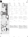
In der Box enthalten
Inside the box
Dans le boîtier
Nella scatola
Dentro de la caja
Product binnen in
Sie benötigen
You’ll need
Éléments nécessaires
Avrete bisogno di
Usted necesitará
Wat hebt u nodig
3 x Aufkleber / 3 x Sticker
3 x autocollant / 3 x adesivo
3 x etiqueta adhesiva / 3 x sticker
5.5m Kabel / 5.5m Cable / 5.5m câble / 5.5m cavo / 5.5m cable/ 5.5m kabel
M16 Gummitüllle
M16 Rubber Grommet
M16 passe-câble
M16 guarnizione
M16 arandela
M16 doorvoer
Spannwerkzeug
Strap tool
Outil de serrage
Strumento di tensionamento
Herramienta tensora
Bevestigingsgereedschap
RF-Controller E
www.thornlighting.com
No:. XX-XX-xx-xxx-xxxxx
4X Klemme
4X Terminal
4X Borne
4X Morsetto
4X borne
4X klem
M16 Kabelverschraubung
M16 Cable Gland
M16 presse-étoupe
M16 serracavo
M16 pasamuros
M16 kabelwartel
DC- DC+
RF Controller E
DA / 1-10+
DA/ 1-10-
L in
N in
DA / DC + = Schwarz/Black/Noire/Nero/Negro/Zwart
DA / DC - = Grau/Grey/Grise/Grigio/Gris/Grijs
PE = Grün/Green/Vert/Verde/Verde/Groen
N in = Blau/Blue/Bleu/Blu/Azul/Blauw
Wire color description
L in = Braun/Brown/Marron/Marrone/Marrón/Bruin
DRIVER
PE
N
L
DA / DC+
DA / DC-
JUNCTION BOX
PENL
PENL
RF Controller E - 180808.indd 1-3 08/08/2018 13:33:45

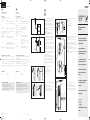
Montage
Installation
Montage
Montaggio
Montaje
Montage
1. DE: Schieben Sie die Kabelverschraubung/Gummitülle über das Kabel.
Hinweis: Ein Teil der UV-Hülse muss in der Kabelverschraubung verbleiben.
1. EN: Push Cable Gland/Grommet over the cable
Note: Leave some UV Sleeve in the Cable Gland/Grommet.
1. FR: Pousser le presse-étoupe/passe-câble par dessus le câble. Remarque:
laisser un peu de gaine UV dans le presse-étoupe
1. IT: Spingere il serracavo/pressacavo sopra il cavo. Indicazione: lasciare un po‘
di boccola UV nel serracavo.
1. ES: Ajuste el cable en el pasamuros/pasacables. Nota: deje espacio para el
tubo UV en el pasamuros
1. NL: Haal de kabel door de kabelwartel/kabeldoorvoer
Opmerking: Laat een deel van de UV-kabelhuls in de kabelwartel zitten
5. DE: Befestigen Sie das Produkt mit dem Riemen am Mast.
5. EN:Strap product to pole
5. FR: Attacher le produit au poteau
5. IT: Fissare con nastro il prodotto al palo.
5. ES: Fije el producto al poste
5. NL: Maak het product aan de pool vast
2. DE: Bringen Sie am Mast in der Höhe von 5m eine 16mm-Bohrung an (mit
M16 Gewindebohrung bei Verwendung einer Kabelverschraubung). Hinweis:
Für einen zusätzlichen Rostschutz empfiehlt sich die Verwendung eines
Korrosionsschutzsprays.
2. EN: Drill 16mm hole (M16 threaded if using Cable Gland) into pole 5m
Note: For added protection against rust, the use of an anti-corrosion spray is
recommended.
2. FR: Percer un trou 16mm (un M16 fileté en cas d’utilisation d’un presse-
étoupe) dans le poteau à une hauteur de 5m. Remarque: il est recommandé
d’utiliser un spray anticorrosion pour une protection supplémentaire contre la
rouille
2. IT: Praticare un foro 16mm (un M16 filettato se si usa il serracavo) nel palo a
un‘altezza di 5 m. Indicazione: per aumentare la protezione contro la ruggine, si
consiglia di utilizzare uno spray anticorrosione.
2. ES: Realice un agujero 16mm (un M16 roscado en caso de utilizar un
pasamuros) en el poste a una altura de 5 m. Nota: para aumentar la protección
contra oxidación, se recomienda utilizar un espray anticorrosión
2. NL: Boor een 16mm-gat (een M16 schroefdraadgat in het geval van
een kabelwartel) in de pool op een hoogte van 5 m. Opmerking: Voor extra
bescherming tegen roest wordt het gebruik van een corrosiewerende spray
aanbevolen
6. DE: Bringen Sie den Produkt-ID-Aufkleber auf dem Mast an. Kontrollieren Sie,
dass die Aufkleber am Mast und am Produkt identisch sind.
6. EN: Apply product ID sticker to pole. Ensure ID sticker of product and pole
are the same.
6. FR: Apposer l‘autocollant d‘identification du produit sur le poteau. Vérifier
que l‘autocollant d‘identification du produit et du poteau sont identiques.
6. IT: Applicare l‘adesivo con l‘ID del prodotto all‘asta. Accertare che gli adesivi
con l‘ID del prodotto e dell‘asta coincidano.
6. ES: Aplique la etiqueta adhesiva de identificación de producto al poste.
Asegúrese de que las etiquetas adhesivas de identificación del producto y del
poste sean las mismas.
6. NL: Breng een product-ID sticker op de pool aan. Controleer of de ID-sticker
van het product en de pool identiek zijn.
3. DE: Führen Sie das Kabel durch die Bohrung am Mast.
3. EN: Run wire into hole in pole
3. FR: Faire passer le câble à travers le trou du poteau
3. IT: Introdurre il filo nel foro del palo.
3. ES: Pase el cable por el agujero del poste
3. NL: Haal de kabel door het gat in de pool
4. DE: Setzen Sie die Kabelverschraubung/Gummitülle in die Bohrung am Mast
ein.
4. Insert Cable Gland/Grommet into hole in pole
4. FR: Insérer le presse-étoupe/passe-câble dans le trou du poteau
4. IT: Inserire il serracavo/pressacavo nel foro del palo.
4. ES: Inserte el pasamuros/pasacables en el agujero del poste
4. NL: Steek de kabelwartel/kabeldoorvoer in het gat in de pool
7. DE: Führen Sie die Verbindung gemäß Schaltplan durch.
7. EN: Connect as shown in wiring diagram.
7. FR: Connecter le câble comme indiqué sur le schéma de câblage.
7. IT: Collegare come mostrato nel diagramma di cablaggio.
7. ES: Conecte como se muestra en el diagrama de cableado.
7. NL: Maak een verbinding zoals weergegeven in het bedradingsschema.
5m
Twist the end
leads of the wires
OR
TVILIGHT
www.tvilight.com
TVI-SKL1-01-0014
TVILIGHT
www.tvilight.com
TVI-SKL1-01-0014
www.thornlighting.com
No:. TH-GE-xx-xxx-xxxxx
www.thornlighting.com
No:. TH-GE-xx-xxx-xxxxx
SAME
www.thornlighting.com
No:. TH-GE-xx-xxx-xxxxx
1 m
Brown
Blue
Purple /Black
Grey
AC in(L)
AC in(N)
DC +
DC -
Green
GND
Connector
(e.g. Wago )
AC in(N)
AC in(L)
DC-
DC +
Junction Box
GND
L
N
OR
Hereby, Thorn declares that the radio
equipment type is in compliance with
Directive 2014/53/EU.
Hiermit erklärt Thorn für diesen
Funkanlagentyp die Übereinstimmung
mit der Richtlinie 2014/53/EU.
Par la présente Thorn déclare que
l'équipement radioélectrique est
conforme à la directive 2014/53/UE.
The full text of the EU declaration is
available at the following internet
address:
Der vollständige Text der EU Erklärung
ist zu finden auf der folgenden
Internetseite:
Le texte complet se trouve à l‘adresse
Internet suivante
www.thornlighting.com/ (+ product code
8 digits)
Radio Equipment Directive
2014/53/EU
EU DECLARATION OF
CONFORMITY
(DoC - RED)
OR
* Ensure Tensioning Tool is set
to maximum tension (#4)
Tensioning Tool
nl
Toepassing
Externe draadloze lichtcontroller
Technische gegevens
Nominale ingangsspanning ........230 VAC, 50/60 Hz
Tolaatbare ingangsspanning .......207 – 253 V, 50 – 60 Hz
Stroomverbruik .................max. 30mA
Interface . . . . . . . . . . . . . . . . . . . . . . 1 uitgang (DA/DA-aansluitklemmen) voor maximaal 2 DALI-conforme
bedrijfsapparaaten of 1 1-10 V voorschakelapparaat
Veiligheidsklasse ................Klasse II
Elektrische veiligheid .............Galvanische isolatie tussen hoogspannings- en
laagspanningsaansluitklemmen
Tolaatbare omgevingscondities .....-20 to +70°C, 20 – 90% Rh niet-condenserend
Tolaatbare behuizingstemperatuur...Max. +85 °C
Productmontage ................ Op de paal
Beschermingsklasse .............IP 65
Materiaal behuizing ..............Polycarbonaat (PC-ABS), vlambestendig (UL94V0)
Afmetingen .................... RF-Controller E: 148 x 50 x 58 (D x B x H, in mm)
Astroklok ...................... Real-time klok met batterij-opslag
Geavanceerde kalender en locatiegerelateerde tijdschema (incl.
automatische klokweergave van zonsopkomst – zonsondergang en
zomer – wintertijd)
Gewicht.......................680 g
Draadloze communicatie . . . . . . . . . . 2,4 GHz IEEE 802.15.4 zelfvormend, zelfherstellend draadloos
netwerk +10 dBm max. zendvermogen.
Instructies voor planning en installatie
• Voor een goede werking moet RF-Controller E worden verbonden met een dimbare stuurprogramma/
voorschakelapparaat.
LET OP: Bepaalde dimbare stuurprogramma’s/voorschakelapparaten moeten worden in de dimbare
modus worden geprogrammeerd/ingesteld. Als dit niet gebeurd is, kan RF-Controller E het verbonden
verlichtingstoestel niet dimmen.
• De standaardinstelling van de RF-Controller E zijn 100% zonder RF-netwerkverbinding.
• Omschakeltijd, systeemstoringsniveau, stroom op niveau: worden standaard geregeld via de CMS.
Statuslampjes
Groen ........................Verbonden
Rood .........................Zoekt naar RF-netwerk
Veiligheidsinstructies
• Het apparaat mag uitsluitend worden gebruikt voor het gespecificeerde toepassing.
• Relevante gezondheids- en veiligheidsregels dienen in acht te worden genomen.
• Alleen gekwalificeerd personeel mag het apparaat monteren, installeren en in bedrijf stellen.
• Als er een fout optreedt, kunnen er gevaarlijke spanningsniveaus aanwezig zijn op de DALI-
aansluitklemmen en op de DALI-stuurleiding.
es
Ámbito de aplicación
Controlador de iluminación inalámbrico externo
Datos técnicos
Tensión nominal de entrada........230 VAC, 50/60 Hz
Tensión de entrada permisible ...... 207 – 253 V, 50 – 60 Hz
Carga energética................ máx. 30mA
Interfaz . . . . . . . . . . . . . . . . . . . . . . . 1 salida (bornes de conexión DA/DA) para un máximo de 2
dispositivos de control diseñados conforme a DALI, o 1 balasto 1 –
10 V
Clase de protección .............Clase II
Seguridad eléctrica ..............Aislamiento galvánico entre los bornes de conexión de alta tensión y
baja tensión
Condiciones ambientales admisibles .-20 a +70°C, 20 – 90% humedad relativa sin condensación
Temperatura permisible de la caja...+ 85 ° C como máximo
Montaje del producto ............ En el poste
Grado de protección .............IP 65
Material de la carcasa . . . . . . . . . . . . Policarbonato (PC-ABS), ininflamable (UL94V0)
Dimensiones ................... RF-Controller E: 148 x 50 x 58 (PrxAnxAl, en mm)
Astro-reloj ..................... Reloj en tiempo real con respaldo de batería
Calendario avanzado y horario basada en la localización (incluye
reloj automático de salida y puesta de sol y verano-invierno)
Peso .........................680 g
Comunicación inalámbrica. . . . . . . . . 2,4 GHz IEEE 802.15.4 red inalámbrica de auto-formación y
autorreparación potencia de transmisión máxima, +10 dBm.
Notas de planificación e instalación
• Para funcionar adecuadamente, el RF-Controller E se tiene que conectar a un accionador/balasto
regulable.
NOTA: Algunos accionadores/balastos regulables tienen que ser programados/configurados a un
modo regulable. Si esto no se ha hecho, el RF-Controller E no podrá atenuar gradualmente la luminaria
conectada.
• La configuración predeterminada del RF-Controller E es 100% sin conexión de red de RF.
• Tiempo de desvanecimiento, nivel de falla de sistema, nivel de encendido de poder: serán determinados
por CMS.
LED de estado
Verde......................... Conectado
Rojo .........................Buscando red RF
Instrucciones de seguridad
• El aparato solo se puede usar para el ámbito de aplicación especificado.
• Deben observarse las normas de seguridad y salud relevantes.
• Sólo personal calificado puede montar, instalar y poner en operación el aparato.
• Si se produce un error, pueden estar presentes niveles peligrosos de voltaje en los bornes de
conexión DALI y en la línea de control DALI.
INSTALLATION RF-Controller E
RF-Controller E 96628009
Thorn Lighting Ltd
Green Lane Industrial Estate, DL16 6HL Spennymoor, UK
www.thornlighting.com PR161337 Rev. B
RF Controller E - 180808 ©
RF Controller E - 180808.indd 4-6 08/08/2018 13:33:46
-
 1
1
-
 2
2


