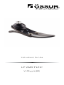
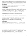
Össur LP VARI-FLEX VLPE Series Instructions For Use Manual
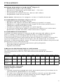
- Tipo
- Instructions For Use Manual

Instructions for Use
LP VARIFLEX
®
VLPExyyzs(BR)

EN | Instructions for Use
DE | Gebrauchsanweisung
FR | Notice d’utilisation
ES | Instrucciones para el uso
IT | Istruzioni per l’uso
DA | Brugsanvisning
SV | Bruksanvisning
EL | ΟδηγΙες χρΗσης
NL | Gebruiksaanwijzing
PT | Instruções de Utilização
JA | 取扱説明書
ZH | 中文说明书
KO | 사용 설명서

3
")
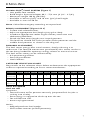
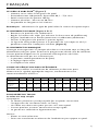
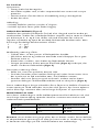
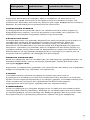
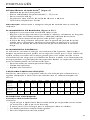
L M
1/2 1/2
1/2 1/2
P A
1/3 1/3 1/3
1/2 1/2
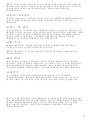
1
2
3
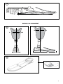
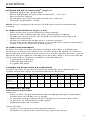
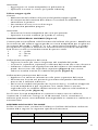
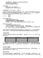
BENCH ALIGNMENT

4
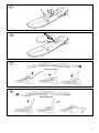
Insertion
Removal

5PB
ENGLISH
LP VARIFLEX
®
FOOT SYSTEM Figure
• Low profile foot module
• Build height: Pyramid adapter , – , mm ( /" - /")
• Maximum weight kg ( lbs)
• Available in mm (/") and mm (/") heel height
• Available in sizes - cm
N: Select foot category according to impact level.
BENCH ALIGNMENT Figure &
• Fit foot with selected cover.
• Adjust to appropriate heel height (using the shoe).
• Introduce appropriate socket angles flexion/ extension and
abduction/adduction.
• Divide the foot cover length into equal portions.
• The load line should fall at the junction of the posterior and the
middle third portions as shown in the diagram.
DYNAMIC ALIGNMENT
The heel stores energy after initial contact, slowly releasing it at
midstance. The forward momentum generated by this action results in
the toe being loaded for optimum energy release at terminal stance.
The heel to toe action can be influenced by
• A-P positioning of foot
• Dorsi-Plantarflexion
• Heel Stiffness
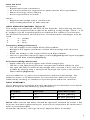
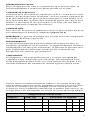
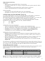
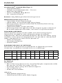
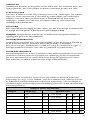
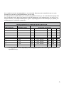
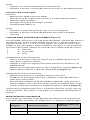
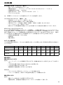
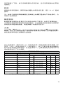
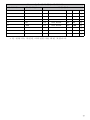
CATEGORY SELECTION CHART
Please refer to the selection charts below to determine the appropriate
stiffness required according to Össur recommendations.
HEEL STIFFNESS
Heel too soft
Symptoms
• Foot will come to flat position too early (amputee feels he/she is
sinking into a hole).
• Extra energy is required to climb up over the toe.
• Toe will feel too stiff.
• Knee may hyperextend.
Action
• Add polyurethane heel wedge.
• Shift socket anterior (or foot posterior).
WEIGHT KG - - - - - - - - - -
WEIGHT LBS - - - - - - - - - -
Low
Impact Level
Moderate
Impact Level
N/A
High
Impact Level
N/A N/A

6
Heel too hard
Symptoms
• Rapid heel to toe movement
• At initial contact the amputee has poor control of his prosthesis
• Minimal energy return feeling
• Knee may become unstable
Action
• Replace heel wedge with a smaller one.
• Shift socket posterior or foot anterior.
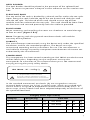
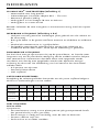
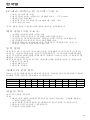
HEEL WEDGES CM Figure
The wedge can influence the heel to toe function. Start altering the heel
resistance to improve foot response by adding a heel wedge. The °, ° &
° wedges can be interchanged to customize the stiffness and achieve
the desired functional characteristics. A combination of wedges may be
used
. ° – yellow
. ° – red
. ° – blue
Temporary Wedge Placement
• Cut the wedge to the width of the foot module.
• Roughen the upper and lower surface of the wedge with abrasive
paper.
• Place the wedge in the angle of heel and foot module.
• Secure in position bond to upper surface (Figure ) with tape wrapped
around the foot module (Figure ).
Permanent Wedge Placement
• Apply adhesive on the upper side of the wedge only.
• Locate in the foot/heel junction and position before adhesive sets.
• For split toe feet install the heel wedge then remove a thin slice in the
middle by cutting with a sharp knife through the split in the carbon
foot module (Figure ).
Instant adhesive is necessary to bond the urethane heel wedge. The
adhesive cures in - seconds. For removal the adhesive may be
softened by soaking in acetone or cyanoacrylate adhesive remover.
HEEL ASSEMBLY
If it is necessary to replace the heel component or heel bolts use Loctite
and torque to the following specifications:
N: After service the bolts should be tightend, allowed to set for a few
minutes and then tightened again. A biannual inspection of attachment
bolts is recommended:
Check for corrosion and sign of wear. Replace bolts if needed.
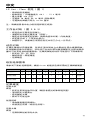
Category Bolt Size Heel Bolt Torque
- ⁄" Nm (ft-lbs)
- ⁄" Nm (ft-lbs)

76
HEEL DIVIDER
The heel divider should be placed in the posterior of the splitted heel
part. To secure its position a drop of instant adhesive can be used on one
side.
FLEXFOOT SOCK
The toe end of the sock is divided by a thread and fits within the toe split.
Upon fitting the sock, hold the top of the toe thread and slide the sock
into the toe split. The thread of the sock should rest on top of foot
module and not underneath the toe split. The sock should be loose from
the heel area and secured proximally with the cable tie provided.
SHOE HORN
When removing and installing the cover use shoehorn to avoid damage
to foot or cover (Figure & ).
N: Tampering with the pyramid attachment bolts will void the
warranty of the product
LIABILITY
The manufacturer recommends using the device only under the specified
conditions and for the intended purposes. The device must be
maintained according to the instructions for use. The manufacturer is
not liable for damage caused by component combinations that were not
authorized by the manufacturer.
COMPLIANCE
This component has been tested according to ISO standard to two
million load cycles. Depending on the amputee’s activity this
corresponds to a duration of use of two to three years. We recommend
carrying out regular yearly safety checks.
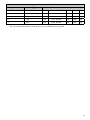
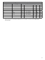
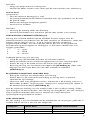
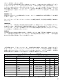
ISO 10328 - “P” - “m”kg *)
*) Body mass limit not to be exceeded!
For specic conditions and limitations of use see
manufacturer’s written instructions on intended use!
In the standard mentioned, test levels (P) are assigned to a certain
maximal body masses (m in kg). In some cases, which are marked with,
no test level is assigned to the product related maximal body mass. In
these cases, the test loads have been adapted adequately on the basis of
the specified load level.
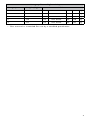
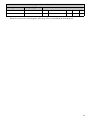
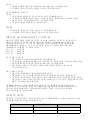
Category Össur high activity
Category Weight (Kg) Lable text
P ISO - P kg
P ISO - P kg
P ISO - P kg
P ISO - P kg

8
Category Össur high activity
Category Weight (Kg) Lable text
P ISO - P kg
P ISO - P kg
P ISO - P kg
P ISO - P kg
P ISO - P kg
• This manual is intended for use by a certified prosthetist.

98
DEUTSCH
LP VARIFLEX
®
FUSSSYSTEM Abbildung
• Low Profile Fußmodul
• Bauhöhe: Pyramidenadapter , – , mm
• Gewichtsgrenze: kg
• Erhältlich für Absatzhöhen: mm, mm
• Erhältlich in den Größen -
B: Wählen Sie je nach Mobilitätsgrad die Fußkategorie.
STATISCHER AUFBAU Abbildung &
• Bauen Sie die Prothese mit Hilfe eines Schuhes in der gewünschten
Absatzhöhe ( oder mm) so auf, dass das Rohr in o Position
zum Boden steht.
• Richten Sie die passende Schaftflexion ein.
• Unterteilen Sie den Fuß der Länge nach in drei gleiche Teile (eine
Markierung an Kosmetikrand ist vorgegeben).
• Die seitliche Lotlinie fällt, wie in der Abbildung dargestellt, durch die
Markierung.
DYNAMISCHE AUSRICHTUNG
Der LP Vari-Flex speichert durch seine spezielle Konstruktion beim
Fersenauftritt Energie. Die gespeicherte Energie wird im weiteren
Schrittzyklus freigegeben und unterstützt damit die “Tibiale Progression”.
Dadurch entsteht eine Vorwärtsdynamik die eine optimale
Energiefreigabe am Ende des Abrollvorgangs gewährleistet. Die
Abrollphase kann durch die folgenden Faktoren beeinflusst werden:
• A-P Positionierung des Fußes
• Dorsi-Plantarflexion
• Absatzsteifheit
KATEGORIEAUSWAHLTABELLE
Entnehmen Sie bitte die korrekten, von Össur empfohlenen
Steifigkeitswerte der nachfolgenden Auswahltabelle.
ABSATZHÄRTE
Der Absatz ist zu weich
Symptome
• Der Prothesenträger hat das Gefühl in einem Loch zu versinken (der.
Fuß liegt zu früh flach auf).
• Der Prothesenträger hat das Gefühl, gegen einen ãBerg“ zu laufen
(zusätzliche Energie wird benötigt, um über den Vorfuß abzurollen).
• Der Vorfuß fühlt sich zu steif an.
• Das Knie kann überstrecken (Genu-Recurvatum).
Was zu tun ist:
• Fügen Sie einen Fersenkeil ein.
GEWICHT KG - - - - - - - - - -
Geringe
Belastung
Mittlere
Belastung
N/A
Hohe
Belastung
N/A N/A

10
• Wenn Sie bereits einen Fersenkeil benutzen, wechseln Sie zur
nächsten Größe.
• Verschieben Sie den Schaft nach vorne oder den Fuß nach hinten.
• Wird das gewünschte Ergebnis nicht erzielt, überprüfen Sie die
Kategorie entsprechend der Auswahltabelle.
Der Absatz ist zu steif.
Symptome
• Beim Fersenauftritt hat der Prothesenträger nur unzureichende
Kontrolle über die Prothese.
• Zu schnelle Abrollbewegung.
• Minimale Energierückgabe.
• Die J-Feder des Flex-Foot wird beim Fersenauftritt nicht richtig
aufgebogen
• Bei unzureichender Muskulatur kann das Knie in die Flexion
(Beugung) gedrückt werden
Was zu tun ist:
• Wenn Sie bereits einen Fersenkeil benutzen, wählen Sie die nächst
kleinere Größe oder verwenden Sie den Fuß ohne Fersenkeil.
• Verschieben Sie den Schaft nach hinten oder den Fuß nach vorne.
• Wird das gewünschte Ergebnis nicht erzielt, überprüfen Sie die
Kategorie Ihres Flex-Foot und wählen Sie gegebenenfalls die nächst
kleinere Kategorie.
FERSENKEILE CM Abbildung
Die Absatzkeile können die Abrollfunktion des Fußes beeinflussen.
Beginnen Sie damit, den Absatzwiderstand zu verändern, um die
Resonanz des Fußes zu verbessern, indem Sie Absatzkeile hinzufügen.
Die °, ° & ° Keile können ausgetauscht werden um die Steifheit zu
regulieren und andere gewünschte Funktionsmerkmale zu erhalten. Die
Absatzkeile können auch kombiniert verwendet werden.
. ° – gelb
. ° – rot
. ° – blau
Befestigung des Fersenkeils zur Anprobe
• Rauen Sie den Fersenkeil auf beiden Seiten mit Schleifpapier an.
• Positionieren Sie den Keil so in den Winkel zwischen Absatz und
Fußmodul, dass er auf beiden Seiten gleich weit herausragt.
• Fixieren Sie den Keil mit Klebeband (Abbildung ) oder einem Tropfen
Loctite am hinteren Keilrand.
• Entfernen des Absatzkeils: Ziehen Sie ihn heraus, falls notwendig, mit
Hilfe einer Kombizange.
Permanente Befestigung des Fersenkeils
• Schneiden Sie den Keil passend zur Breite des Fußmoduls zu.
• Bringen Sie Loctite auf die Oberseite des Keils auf.
• Setzen Sie ihn in den Winkel zwischen Absatz und Fußmodul ein.
• Bei einem Split-Toe Modell müssen Sie den Keil nach dem Einbau mit
einem scharfen Messer in der Mitte längs durchtrennen (
Abbildung
).
• Wenn Sie den Keil nun noch einmal entfernen müssen, schneiden Sie
ihn vorsichtig mit einem scharfen Messer frei. Verwenden Sie aus
Sicherheitsgründen diesen Keil nicht mehr.

1110
ABSATZAUFBAU
Falls Absatzmodul oder Befestigungsschrauben ausgetauscht werden
müssen, sichern Sie mit Loctite und drehen Sie nach den den
folgenden Angaben fest:
A: Nach einer Demontage der Fersenfeder sollten die
Fersenbefestigungsschrauben nach kurzer Wartezeit (- Minuten) unter
Verwendung von Loctite ein zweites Mal auf das angegebene
Drehmoment angezogen werden.
Wir empfehlen eine Kontrolle der Befestigungsschrauben alle Monate.
Achten Sie auf Zeichen von Korrosion und/oder Verschleiss. Wechseln
Sie die Schrauben bei Bedarf.
ABSATZTRENNER
Der Absatztrenner sollte im hinteren Teil des gesplitteten
Absatzbereiches positioniert werden. Zur Sicherung können Sie einen
Tropfen Sekundenkleber auf eine Seite geben.
FLEXFOOTSOCKE
Beim Anziehen der Socke darauf achten, dass die Naht im Zehenbereich
nicht unter sondern über dem Fußmodul positioniert wird.Die Socke
sollte im Absatzbereich locker sitzen und proximal mit dem beiliegenden
Kabelbinder gesichert werden.
SCHUHLÖFFEL
Um Beschädigungen von Fuß oder Kosmetik zu vermeiden, benutzen Sie
den hierfür eigens konstruierten Schuhlöffel zum Entfernen und
Einsetzen der Kosmetik (Abbildung & ).
HINWEIS: Unerlaubte Eingriffe an den Pyramidenbefestigungsschrauben
führen zum Verlust der Produktgarantie.
HAFTUNG
Der Hersteller empfiehlt, das Gerät nur unter den angegebenen
Bedingungen und zu den vorgesehenen Zwecken zu verwenden. Die
Vorrichtung muss entsprechend den Gebrauchshinweisen gepflegt
werden. Der Hersteller haftet nicht für Schäden, die durch Kombination
von Komponenten verursacht werden, die nicht vom Hersteller
zugelassen sind.
NORMKONFORMITÄT
Diese Komponente wurde nach ISO-Norm mit zwei Millionen
Belastungszyklen getestet. Je nach Aktivität des Amputierten entspricht
dies einer Haltbarkeit von zwei bis drei Jahren. Wir empfehlen,
regelmäßige jährliche Sicherheitsüberprüfungen durchzuführen
Kategorie Schraubenlänge Drehmoment
- ⁄" Nm
- ⁄" Nm

12
Die obengenannte Norm sieht vor, dass die Prüfungsstufen (P) einer
maximalen Körpermasse (m in kg) zugeordnet werden. In einigen Fällen,
die markiert sind, wird kein Prüfungsgrad der maximalen Körpermasse
für das Produkt zugeornet. In diesen Fällen wurden die Testbelastungen
entsprechend der Basis der angegebenen Belastungsgrade angepasst.
Kategorie Össur hohe Aktivität
Kategorie Gewicht (kg) Etikettentext
P ISO - P kg
P ISO - P kg
P ISO - P kg
P ISO - P kg
P ISO - P kg
P ISO - P kg
P ISO - P kg
P ISO - P kg
P ISO - P kg
• Dieses Handbuch ist für den Einsatz seitens eines zertifizierten
Prothetikers gedacht.

1312
FRANÇAIS
LE PIED LP VARIFLEX
®
Figure
• Hauteur mini selon la longueur du pied.
• Encombrement: Adaptateur Pyramidal , – , mm
• Poids maximum du patient kg
• Hauteur de talon : mm ou mm
• Disponible en longueurs à cm
R : sélectionner le type de pied selon le niveau d’impact requis.
ALIGNEMENT DE BASE Figure &
• Recouvrir le pied de son revêtement.
• Régler la hauteur du talon (en utilisant la chaussure de préférence)
• Aligner l’emboîture en flexion/extension et adduction/abduction.
• Diviser la longueur du pied en parties égales.
• La ligne de charge doit passer à la jonction du / moyen et du /
postérieur comme l’indique le schéma (Figure ).
ALIGNEMENT DYNAMIQUE
L’énergie emmagasinée à l’attaque du talon est restituée tout au long du
déroulement du pas pour favoriser la progression tibiale afin de solliciter
l’avant-pied et d’optimiser la restitution d’énergie lors de l’élan.
Le déroulement du pas est influencé par:
• la position antéro-postérieure du pied,
• le réglage équin-talus,
• la souplesse du talon
GUIDE DE SÉLECTION DES CATÉGORIES
Veuillez vous référer aux tableaux de sélection ci-dessous pour
déterminer la rigidité appropriée requise, conformément aux
recommandations d'Össur.
SOUPLESSE DU TALON
Le talon est trop souple
Symptômes
• La flexion plantaire est trop rapide (les amputés ressentent
l’impression de s’enfoncer dans un trou).
• Un effort est nécessaire pour passer sur l’avant-pied.
• L’avant-pied est ressenti comme étant trop rigide.
• Le genou est sollicité en hyperextension.
Actions
• Placer un coin talonnier.
• Faire une translation antérieure de l’emboîture par rapport au pied.
POIDS KG - - - - - - - - - -
Faible niveau
d'impact
Niveau
d'impact
modéré
N/A
Niveau
d'impact élevé
N/A N/A

14
Le talon est trop dur
Symptômes
• Le transfert talon-pointe est trop rapide.
• A l’attaque du talon l’amputé contrôle mal sa prothèse.
• La restitution d’énergie n’est pas ressentie.
• Le genou est instable.
Actions
• Réduire la taille du coin talonnier.
• Faire une translation postérieure de l’emboîture par rapport au pied.
COINS TALONNIERS CM Figure
Le coin talonnier influence le déroulement du pas. Pour améliorer la
réponse du pied il faut adapter la résistance du talon en ajoutant un coin
talonnier. Les coins de °, ° ,° peuvent être interchangés pour
individualiser la souplesse du talon et obtenir les caractéristiques
fonctionnelles désirées. La dimension des coins peut-être modifiée à
l’aide de ciseaux forts. Il est possible de combiner les coins talonniers.
. ° – jaune
. ° – rouge
. ° – bleu
Fixation provisoire du coin talonnier
• Découper le coin à la largeur du module pied puis dépolir les surfaces
supérieure et inférieure du coin à l’aide de papier abrasif.
• Placer le coin dans l’angle formé par le talon et le module de pied.
• Maintenir le coin en place en le ligaturant au module (Figure ) de
pied à l’aide de ruban adhésif (Figure ).
Fixation permanente du coin talonnier
• Appliquer la colle uniquement à la surface supérieure du coin.
• Positionner celui-ci dans l’angle formé par le talon et le module de
pied avant que la colle ne prenne.
• Lorsque le coin est en place, en cas d’option split-toe, découper une
fine lamelle de celui-ci le long de la fente (Figure ).
Utiliser la colle à prise instantanée pour bien fixer le coin. La colle prend
en à secondes. Pour enlever la colle, tremper dans l’acétone ou
utiliser un solvant pour colle à base de cyanoacrylate.
ASSEMBLAGE DU TALON
S’il est nécessaire de remplacer les vis du talon ou le talon, utiliser la
Loctite et serrer selon les couples suivants:
R: après entretien, les boulons doivent être serrés. Les laisser
se stabiliser pendant quelques minutes, puis les resserrer. Nous vous
recommandons de pratiquer une inspection des boulons de fixation deux
fois par an : rechercher les signes de corrosion ou d’usure. Remplacer les
boulons si nécessaire.
Catégorie Diam. de vis Couple de serrage
- ⁄" Nm
- ⁄" Nm

1514
SÉPARATEUR DE TALON
Placer le séparateur de talon au / postérieur de la fente du talon. Le
fixer éventuellement à l’aide d’une goutte de colle sur un côté.
CHAUSSETTE FLEXFOOT
L'extrémité de la chaussette est séparée par un fil et s'insère dans la lame
fendue. Lors de la pose de la chaussette, saisissez la partie supérieure du
fil de séparation et faites glisser la chaussette dans la lame fendue. Le fil
de la chaussette doit se placer sur le module de pied et non sous la lame
fendue. La chaussette ne sera pas tendue sur le talon, elle sera fixée en
position proximale à l’aide des liens fournis.
CHAUSSEPIED
Pour chausser ou enlever le revêtement utiliser le chausse-pied afin de ne
pas endommager le pied ou le revêtement (Figure & ).
REMARQUE: La garantie du produit sera annulée en cas de manipulation
des boulons de fixation à pyramide.
RESPONSABILITÉ
Le fabricant recommande d'utiliser le dispositif uniquement dans les
conditions spécifiées et aux fins prévues. Le dispositif doit être entretenu
conformément aux consignes d'utilisation. Le fabricant ne peut être tenu
pour responsable des dommages causés par des associations de
composants non autorisés par le fabricant.
CONFORMITÉ
Ce composant a été testé conformément à la norme ISO qui
s'applique à deux millions de cycles de charge. Cela correspond à une
durée d'utilisation de deux à trois ans selon l'activité de l'amputé. Il est
conseillé d'effectuer des contrôles de sécurité réguliers chaque année.
Dans la norme standard mentionnée ci-dessus, les niveaux de test (P)
sont attribués à certaines masses corporelles maximales (m en kg). Dans
certains cas toutefois, qui sont indiqués aucune niveau de test n'est
associé à la masse corporelle maximale liée au produit. Dans ces cas, les
charges d'essai ont été adaptées sur la base du niveau de charge indiqué.
Catégorie Össur activité élevée
Catégorie Poids (kg) Information sur étiquette
P ISO - P kg
P ISO - P kg
P ISO - P kg
P ISO - P kg

16
Catégorie Össur activité élevée
Catégorie Poids (kg) Information sur étiquette
P ISO - P kg
P ISO - P kg
P ISO - P kg
P ISO - P kg
P ISO - P kg
• Ce manuel doit être utilisé par un prothésiste agréé.

1716
ESPAÑOL
SISTEMA DE PIE LP VARIFLEX
®
Figura
• Módulo de pie Low profile foot
• Altura: Adaptador de pirámide macho , – , mm
• Peso máximo: kg
• Disponible con altura de talón de mm y mm
• Tamaños disponibles: -
N: Elija la categoría de pie en función del nivel de actividad del
usuario.
ALINEACIÓN ESTÁTICA Figura &
• Forre el pie con el revestimiento seleccionado.
• Ajuste la altura adecuada del talón (utilizando el zapato).
• Introduzca en los encajes los ángulos de flexión/extensión y de
abducción/aducción.
• Divida el revestimiento del pie en partes iguales.
• La línea de carga debe converger en la unión de las partes posterior y
media, como se muestra en el diagrama.
ALINEACIÓN DINÁMICA
Al tocar el suelo, el talón almacena energía que libera a medida que
promueve la progresión tibial hacia la fase media de apoyo. El impulso
generado por este movimiento ejerce una fuerza sobre la puntera, que se
libera de manera óptima al despegarse éste del suelo. La transmisión de
fuerza del talón a la puntera puede verse afectada por
• la posición A-P del pie
• la flexión dorsiplantar
• la rigidez del talón
CUADRO DE SELECCIÓN DE CATEGORÍA
Puede consultar el siguiente cuadro de selección para determinar la
rigidez adecuada según las recomendaciones de Össur.
RIGIDEZ DEL TALÓN
Talón demasiado blando
Síntomas
• El pie vuelve a la posición plana demasiado pronto (los amputados
sienten que se hunden en un hoyo).
• Se necesita energía adicional para despegar la puntera del suelo.
• La puntera se siente demasiado rígido.
• Hiperextensión de la rodilla.
Cómo proceder
• Inserte una cuña para talón de poliuretano.
• Desplace el encaje hacia adelante (o el pie hacia atrás).
PESO EN KG - - - - - - - - - -
Nivel de
impacto bajo
Nivel de
impacto
moderado
N/A
Nivel de
impacto alto
N/A N/A

18
Talón demasiado duro
Síntomas
• Movimiento rápido del talón a la puntera.
• Cuando el talón toca el suelo el amputado tiene poco control sobre
su prótesis.
• La transferencia de energía del suelo al pie es mínima.
• Cabe la posibilidad de una torcedura de la rodilla.
Cómo proceder
• Sustituya la cuña del talón por una más pequeña.
• Desplace el encaje hacia atrás (o el pie hacia adelante).
CUÑAS PARA TALÓN CM Figura
La cuña puede afectar la transmisión de fuerzas del talón a la puntera.
Comience por alterar la resistencia del talón para mejorar el
funcionamiento del pie introduciendo una cuña para talón. Las cuñas de
°, ° & ° pueden intercambiarse para adaptar la rigidez a las
necesidades del usuario y obtener la funcionalidad deseada. Puede
emplearse más de una cuña a la vez, combinándolas.
. ° – amarillo
. ° – rojo
. ° – azul
Colocación de cuña temporal
• Corte la cuña de acuerdo a la anchura del módulo de pie.
• Lije las superficies superior e inferior de la cuña con papel abrasivo.
• Coloque la cuña en el ángulo entre el talón y el módulo de pie.
• Asegúrela en su sitio y fíjela a la superficie superior (Figura )
asiéndola con cinta alrededor del módulo (Figura ).
Colocación de cuña permanente
• Aplique agente adhesivo únicamente a la parte superior de la cuña.
• Colóquela en la juntura entre el pie y el talón y fíjela antes de que el
agente adhesivo seque.
• En el caso del pie versión split toe coloque la cuña y luego retire una
porción delgada en la mitad haciendo un corte a través de las
separaciones del módulo de pie de carbono con un cuchillo afilado
(Figura ).
Se requiere un adhesivo instantáneo para fijar la cuña de uretano. Éste se
seca en ó segundos. Para removerlo puede ablandarlo remojándolo
en acetona o en removedor de agente adhesivo de cianoacrilato.
ENSAMBLAJE DEL TALÓN
Si fuese necesario reemplazar el componente del talón o los pernos para
talón utilice Loctite y aplique la fuerza de torsión indicada a
continuación:
N: Tras haber sometido el equipo a mantenimiento, se deben apretar
los pernos y, luego de esperar unos minutos, deben volverse a apretar.
Tipo Tamaño de perno Talón torsión de perno para
- ⁄" Nm
- ⁄" Nm

1918
Recomendamos someter los pernos de fijación a una inspección bianual,
en la que se debe comprobar si existen indicios de corrosión o desgaste.
En dado caso, sustituya los pernos.
SEPARADOR DE TALÓN
El separador de talón debe colocarse en la parte posterior del talón con
ranura. Para fijarlo en su posición puede utilizarse una gota de adhesivo
instantáneo en un lado.
CALCETÍN FLEX FOOT
El extremo para los dedos del calcetín está dividido por una hebra que
encaja en la división para el dedo gordo. Al colocar el calcetín, sostenga
la parte superior de la hebra para el dedo y deslice el calcetín en la
división para el dedo gordo. La hebra debería descansar en la parte
superior del módulo de pie y no debajo de la división para el dedo gordo.
El calcetín debe estar suelto en la zona del talón y sujeto en la zona
proximal con el cable de sujeción incluido.
CALZADOR
Al poner o retirar el revestimiento utilice el calzador para evitar daños al
pie o al revestimiento mismo (Figura & ).
NOTA: La manipulación de los tornillos del adaptador piramidal anulará
la garantía del producto.
RESPONSABILIDAD
El fabricante recomienda usar el dispositivo únicamente en las
condiciones especificadas y para los fines previstos. El dispositivo debe
mantenerse de acuerdo a lo especificado en las instrucciones para el
uso. El fabricante no se hace responsable de los daños causados por el
uso de combinaciones de componentes que no hayan sido autorizados
por el mismo.
CUMPLIMIENTO
Este componente ha sido probado según la normativa ISO a dos
millones de ciclos de carga. En función del nivel de actividad del
amputado, esto se corresponde con una duración de uso de dos o tres
años. Se recomienda llevar a cabo las revisiones de seguridad anuales
regulares.
En la normativa mencionada, los niveles de prueba (P) se asignan a
ciertas masas corporales máximas (m en kg). En algunos casos, que
están señalados, no se ha asignado ningún nivel de prueba al producto
relacionado con la masa corporal máxima. En estos casos, las cargas de
prueba se han adaptado adecuadamente sobre la base del nivel de carga
especificado.

20
Categorías de actividad alta de Össur
Categoría Peso (Kg) Texto en etiqueta
P ISO - P kg
P ISO - P kg
P ISO - P kg
P ISO - P kg
P ISO - P kg
P ISO - P kg
P ISO - P kg
P ISO - P kg
P ISO - P kg
• Este manual está destinado para el uso de un técnico ortopédico
certificado.
La pagina sta caricando ...
La pagina sta caricando ...
La pagina sta caricando ...
La pagina sta caricando ...
La pagina sta caricando ...
La pagina sta caricando ...
La pagina sta caricando ...
La pagina sta caricando ...
La pagina sta caricando ...
La pagina sta caricando ...
La pagina sta caricando ...
La pagina sta caricando ...
La pagina sta caricando ...
La pagina sta caricando ...
La pagina sta caricando ...
La pagina sta caricando ...
La pagina sta caricando ...
La pagina sta caricando ...
La pagina sta caricando ...
La pagina sta caricando ...
La pagina sta caricando ...
La pagina sta caricando ...
La pagina sta caricando ...
La pagina sta caricando ...
La pagina sta caricando ...
La pagina sta caricando ...
La pagina sta caricando ...
La pagina sta caricando ...
La pagina sta caricando ...
La pagina sta caricando ...
La pagina sta caricando ...
La pagina sta caricando ...
La pagina sta caricando ...
La pagina sta caricando ...
La pagina sta caricando ...
La pagina sta caricando ...
-
 1
1
-
 2
2
-
 3
3
-
 4
4
-
 5
5
-
 6
6
-
 7
7
-
 8
8
-
 9
9
-
 10
10
-
 11
11
-
 12
12
-
 13
13
-
 14
14
-
 15
15
-
 16
16
-
 17
17
-
 18
18
-
 19
19
-
 20
20
-
 21
21
-
 22
22
-
 23
23
-
 24
24
-
 25
25
-
 26
26
-
 27
27
-
 28
28
-
 29
29
-
 30
30
-
 31
31
-
 32
32
-
 33
33
-
 34
34
-
 35
35
-
 36
36
-
 37
37
-
 38
38
-
 39
39
-
 40
40
-
 41
41
-
 42
42
-
 43
43
-
 44
44
-
 45
45
-
 46
46
-
 47
47
-
 48
48
-
 49
49
-
 50
50
-
 51
51
-
 52
52
-
 53
53
-
 54
54
-
 55
55
-
 56
56


Össur LP VARI-FLEX VLPE Series Instructions For Use Manual
- Tipo
- Instructions For Use Manual
in altre lingue
- français: Össur LP VARI-FLEX VLPE Series
- español: Össur LP VARI-FLEX VLPE Series
- Deutsch: Össur LP VARI-FLEX VLPE Series
- português: Össur LP VARI-FLEX VLPE Series
- dansk: Össur LP VARI-FLEX VLPE Series
- 日本語: Össur LP VARI-FLEX VLPE Series
Documenti correlati
-
Össur VARI-FLEX Instructions For Use Manual
-
-
-
-
-
Altri documenti
-
Ottobock 1C68 Manuale utente
-
Otto Bock 1C66 Triton Instructions For Use Manual
-
Invacare C426AB Manuale utente
-
 One For All URC 3910 Black Manuale utente
-
 One For All URC 11-3910 Manuale del proprietario
-
-
 Burton 2009 Bindings Manuale utente
-
bort medical 054 300 Instructions For Use Manual
-
Agilent Technologies InfinityLab Flex Bench Assembly And Use Instructions
-
 Ormed Artromot S3 Operating Instructions Manual


